wiring SSANGYONG KORANDO 2012 Service Manual
[x] Cancel search | Manufacturer: SSANGYONG, Model Year: 2012, Model line: KORANDO, Model: SSANGYONG KORANDO 2012Pages: 1082, PDF Size: 96.1 MB
Page 113 of 1082
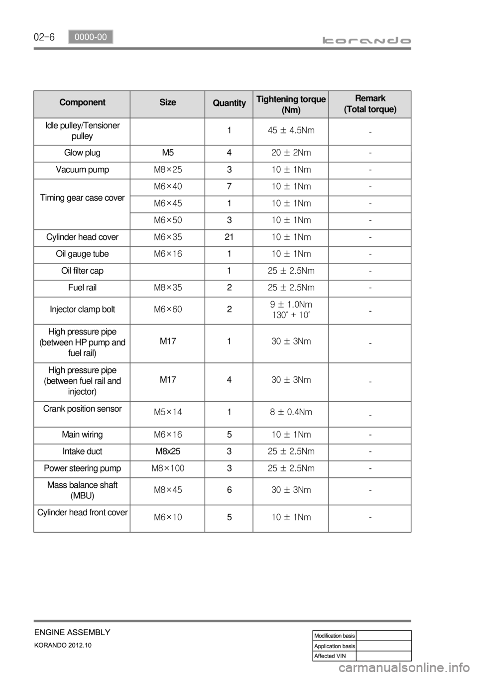
02-6
품명 규격 볼트
수량규정토오크(Nm) 비고
(총 토오크)
Oil gauge tubeM6×16110 ± 1Nm-
Oil filter cap 125 ± 2.5Nm-
Fuel railM8×35225 ± 2.5Nm-
Injector clamp boltM6×6029 ± 1.0Nm
130˚ + 10˚-
High pressure pipe
(between HP pump and
fuel rail)M17 130 ± 3Nm
-
High pressure pipe
(between fuel rail and
injector)M17 430 ± 3Nm
-
Crank position sensor
M5×1418 ± 0.4Nm
-
Main wiringM6×16510 ± 1Nm-
Intake duct M8x25 325 ± 2.5Nm-
Power steering pumpM8×100325 ± 2.5Nm-
Mass balance shaft
(MBU)M8×45630 ± 3Nm-
Cylinder head front cove
rM6×10510 ± 1Nm-
품명 규격볼트
수량규정토오크(Nm)비고
(총 토오크)
Timing gear case coverM6×40710 ± 1Nm-
M6×45110 ± 1Nm-
M6×50310 ± 1Nm-
Cylinder head coverM6×352110 ± 1Nm-
Component Size
QuantityTightening torque
(Nm)Remark
(Total torque)
Idle pulley/Tensioner
pulley145 ± 4.5Nm
-
Glow plug M5 420 ± 2Nm-
Vacuum pumpM8×25310 ± 1Nm-
Page 118 of 1082
02-110000-00
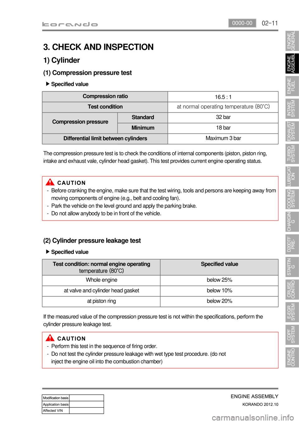
3. CHECK AND INSPECTION
1) Cylinder
(1) Compression pressure test
Specified value ▶
Compression ratio
16.5 : 1
Test conditionat normal operating temperature (80˚C)
Compression pressureStandard32 bar
Minimum18 bar
Differential limit between cylindersMaximum 3 bar
The compression pressure test is to check the conditions of internal components (piston, piston ring,
intake and exhaust vale, cylinder head gasket). This test provides current engine operating status.
Before cranking the engine, make sure that the test wiring, tools and persons are keeping away from
moving components of engine (e.g., belt and cooling fan).
Park the vehicle on the level ground and apply the parking brake.
Do not allow anybody to be in front of the vehicle. -
-
-
(2) Cylinder pressure leakage test
If the measured value of the compression pressure test is not within the specifications, perform the
cylinder pressure leakage test.Specified value ▶
Perform this test in the sequence of firing order.
Do not test the cylinder pressure leakage with wet type test procedure. (do not
inject the engine oil into the combustion chamber) -
-
Test condition: normal engine operating
temperature (80˚C)Specified value
Whole engine below 25%
at valve and cylinder head gasket below 10%
at piston ring below 20%
Page 146 of 1082
03-110000-00
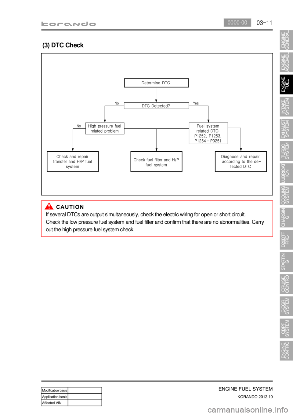
(3) DTC Check
If several DTCs are output simultaneously, check the electric wiring for open or short circuit.
Check the low pressure fuel system and fuel filter and confirm that there are no abnormalities. Carry
out the high pressure fuel system check.
Page 150 of 1082
03-150000-00
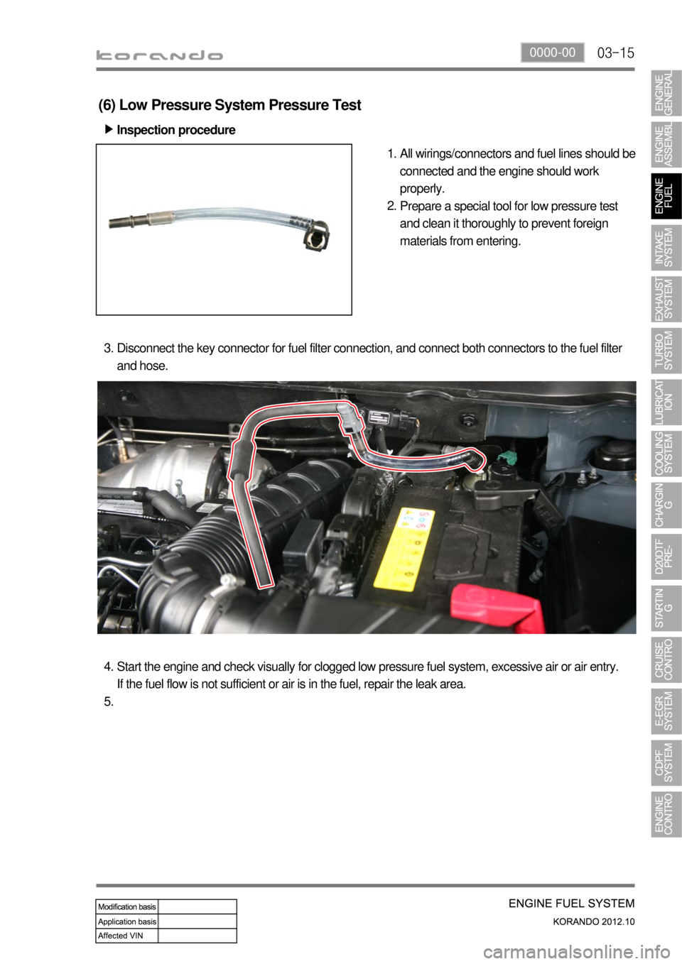
(6) Low Pressure System Pressure Test
Inspection procedure ▶
All wirings/connectors and fuel lines should be
connected and the engine should work
properly.
Prepare a special tool for low pressure test
and clean it thoroughly to prevent foreign
materials from entering. 1.
2.
Disconnect the key connector for fuel filter connection, and connect both connectors to the fuel filter
and hose. 3.
Start the engine and check visually for clogged low pressure fuel system, excessive air or air entry.
If the fuel flow is not sufficient or air is in the fuel, repair the leak area. 4.
5.
Page 207 of 1082
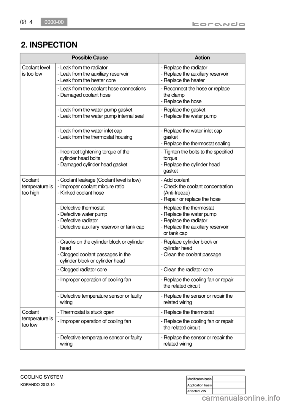
08-4
2. INSPECTION
Possible Cause Action
Coolant level
is too low- Leak from the radiator
- Leak from the auxiliary reservoir
- Leak from the heater core- Replace the radiator
- Replace the auxiliary reservoir
- Replace the heater
- Leak from the coolant hose connections
- Damaged coolant hose- Reconnect the hose or replace
the clamp
- Replace the hose
- Leak from the water pump gasket
- Leak from the water pump internal seal- Replace the gasket
- Replace the water pump
- Leak from the water inlet cap
- Leak from the thermostat housing- Replace the water inlet cap
gasket
- Replace the thermostat sealing
- Incorrect tightening torque of the
cylinder head bolts
- Damaged cylinder head gasket- Tighten the bolts to the specified
torque
- Replace the cylinder head
gasket
Coolant
temperature is
too high- Coolant leakage (Coolant level is low)
- Improper coolant mixture ratio
- Kinked coolant hose- Add coolant
- Check the coolant concentration
(Anti-freeze)
- Repair or replace the hose
- Defective thermostat
- Defective water pump
- Defective radiator
- Defective auxiliary reservoir or tank cap- Replace the thermostat
- Replace the water pump
- Replace the radiator
- Replace the auxiliary reservoir
or tank cap
- Cracks on the cylinder block or cylinder
head
- Clogged coolant passages in the
cylinder block or cylinder head- Replace cylinder block or
cylinder head
- Clean the coolant passage
- Clogged radiator core - Clean the radiator core
- Improper operation of cooling fan - Replace the cooling fan or repair
the related circuit
- Defective temperature sensor or faulty
wiring- Replace the sensor or repair the
related wiring
Coolant
temperature is
too low- Thermostat is stuck open - Replace the thermostat
- Improper operation of cooling fan - Replace the cooling fan or repair
the related circuit
- Defective temperature sensor or faulty
wiring- Replace the sensor or repair the
related wiring
Page 216 of 1082
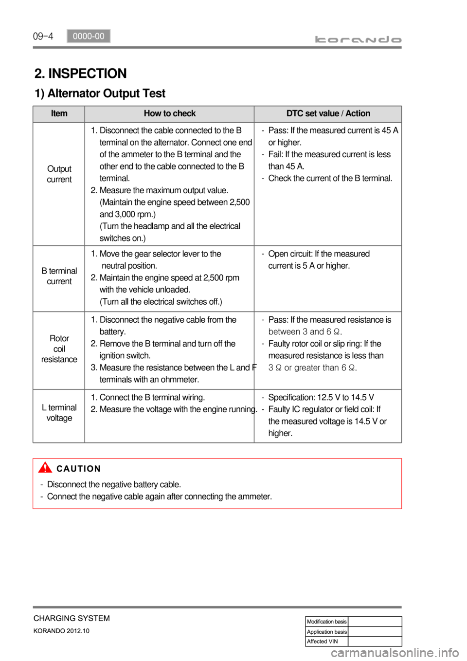
09-4
2. INSPECTION
1) Alternator Output Test
Item How to check DTC set value / Action
Output
current
B terminal
current
Rotor
coil
resistance
L terminal
voltage
Disconnect the cable connected to the B
terminal on the alternator. Connect one end
of the ammeter to the B terminal and the
other end to the cable connected to the B
terminal.
Measure the maximum output value.
(Maintain the engine speed between 2,500
and 3,000 rpm.)
(Turn the headlamp and all the electrical
switches on.) 1.
2.Pass: If the measured current is 45 A
or higher.
Fail: If the measured current is less
than 45 A.
Check the current of the B terminal. -
-
-
Move the gear selector lever to the
neutral position.
Maintain the engine speed at 2,500 rpm
with the vehicle unloaded.
(Turn all the electrical switches off.) 1.
2.Open circuit: If the measured
current is 5 A or higher. -
Disconnect the negative cable from the
battery.
Remove the B terminal and turn off the
ignition switch.
Measure the resistance between the L and F
terminals with an ohmmeter. 1.
2.
3.Pass: If the measured resistance is
between 3 and 6 Ω.
Faulty rotor coil or slip ring: If the
measured resistance is less than
3 Ω or greater than 6 Ω. -
-
Connect the B terminal wiring.
Measure the voltage with the engine running. 1.
2.Specification: 12.5 V to 14.5 V
Faulty IC regulator or field coil: If
the measured voltage is 14.5 V or
higher. -
-
Disconnect the negative battery cable.
Connect the negative cable again after connecting the ammeter. -
-
Page 217 of 1082
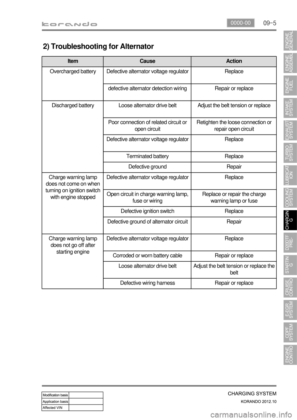
09-50000-00
2) Troubleshooting for Alternator
Item Cause Action
Overcharged battery Defective alternator voltage regulator Replace
defective alternator detection wiring Repair or replace
Discharged battery Loose alternator drive belt Adjust the belt tension or replace
Poor connection of related circuit or
open circuitRetighten the loose connection or
repair open circuit
Defective alternator voltage regulator Replace
Terminated battery Replace
Defective ground Repair
Charge warning lamp
does not come on when
turning on ignition switch
with engine stoppedDefective alternator voltage regulator Replace
Open circuit in charge warning lamp,
fuse or wiringReplace or repair the charge
warning lamp or fuse
Defective ignition switch Replace
Defective ground of alternator circuit Repair
Charge warning lamp
does not go off after
starting engineDefective alternator voltage regulator Replace
Corroded or worn battery cable Repair or replace
Loose alternator drive belt
Adjust the belt tension or replace the
belt
Defective wiring harness Repair or replace
Page 294 of 1082
15-18
This is done periodically under certain operating conditions. When the resetting is finished, the new
minimum pulse value replaces the value obtained during the previous resetting. The first MDP value is
provided by the C3I. Each resetting then allows the closed loop of the MDP to be updated according to
the deviation of the injector.
b. Detection of leaks in the cylinders
The accelerometer is also used to detect any injector which may have stuck open. The detection
principle is based on monitoring the ratio. If there is a leak in the cylinder, the accumulated fuel self-
ignites as soon as the temperature and pressure conditions are favorable (high engine speed, high load
and small leak).
This combustion is set off at about 20 degrees before TDC and before main injection.
The ratio therefore increases considerably in the detection window. It is this increase which allows the
leaks to be detected. The threshold beyond which a fault is signaled is a percentage of the maximum
possible value of the ratio.
Because of the severity of the recovery process (engine shut-down), the etection must be extremely
robust.
An increase in the ratio can be the consequence of various causes:
Pilot injection too much
Main combustion offset
Fuel leak in the cylinder -
-
-
If the ratio becomes too high, the strategy initially restricts the pilot injection flow and retards the main
injection. If the ratio remains high despite these interventions, this shows that a real leak is present, a
fault is signaled and the engine is shut down.
c. Detection of an accelerometer fault
This strategy permits the detection of a fault in the sensor or in the wiring loom connecting the sensor to
the ECU.
It is based on detection of the combustion. When the engine is idling, the detection window is set too low
for the combustion caused by the main injection. If the ratio increases, this shows that the accelerometer
is working properly, but otherwise a fault is signaled to indicate a sensor failure. The recovery modes
associated with this fault consist of inhibition of the pilot injection and discharge through the injectors.
Page 325 of 1082
15-490000-00
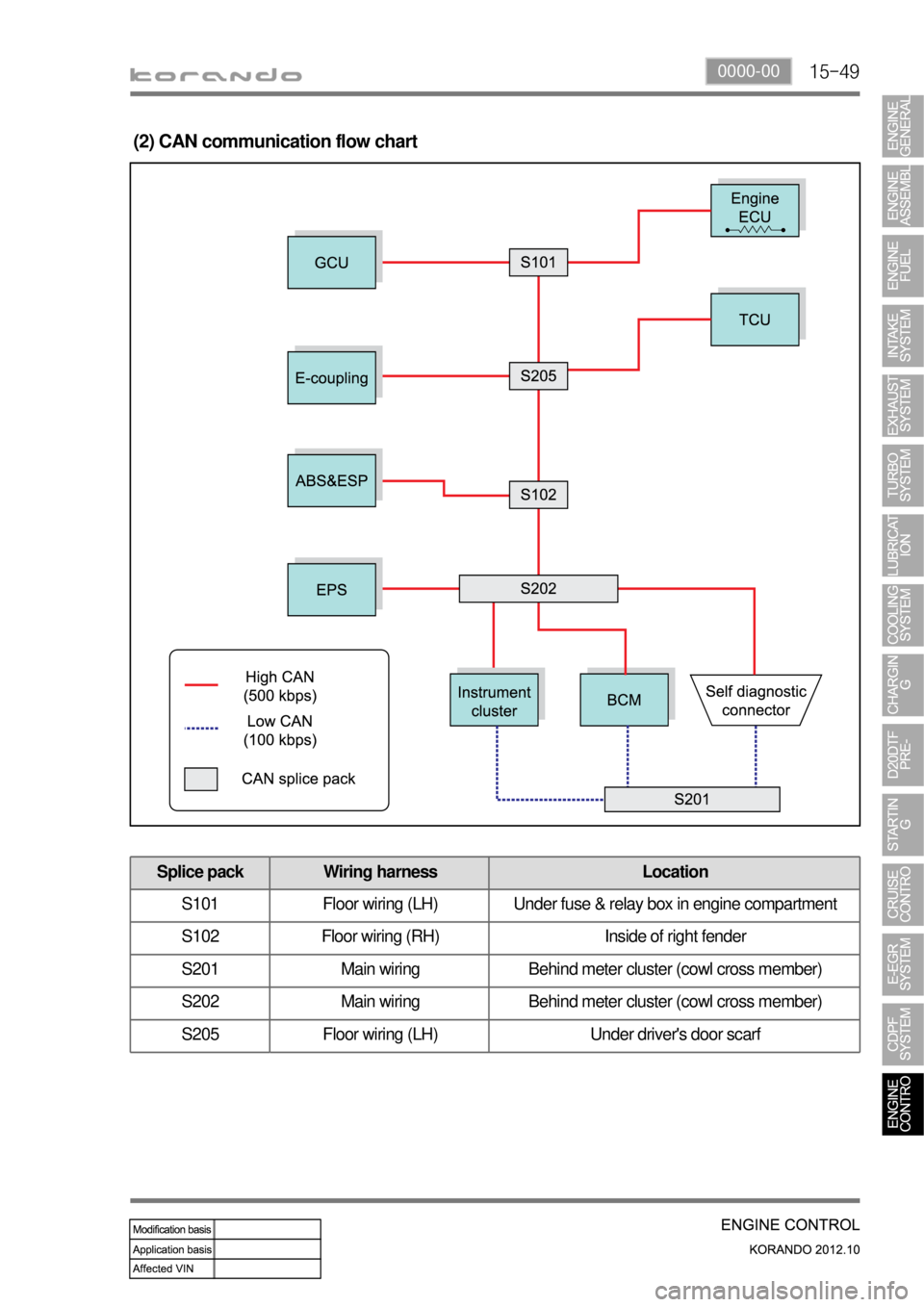
(2) CAN communication flow chart
Splice pack Wiring harness Location
S101 Floor wiring (LH) Under fuse & relay box in engine compartment
S102 Floor wiring (RH) Inside of right fender
S201 Main wiring Behind meter cluster (cowl cross member)
S202 Main wiring Behind meter cluster (cowl cross member)
S205 Floor wiring (LH) Under driver's door scarf
Page 348 of 1082
01-24
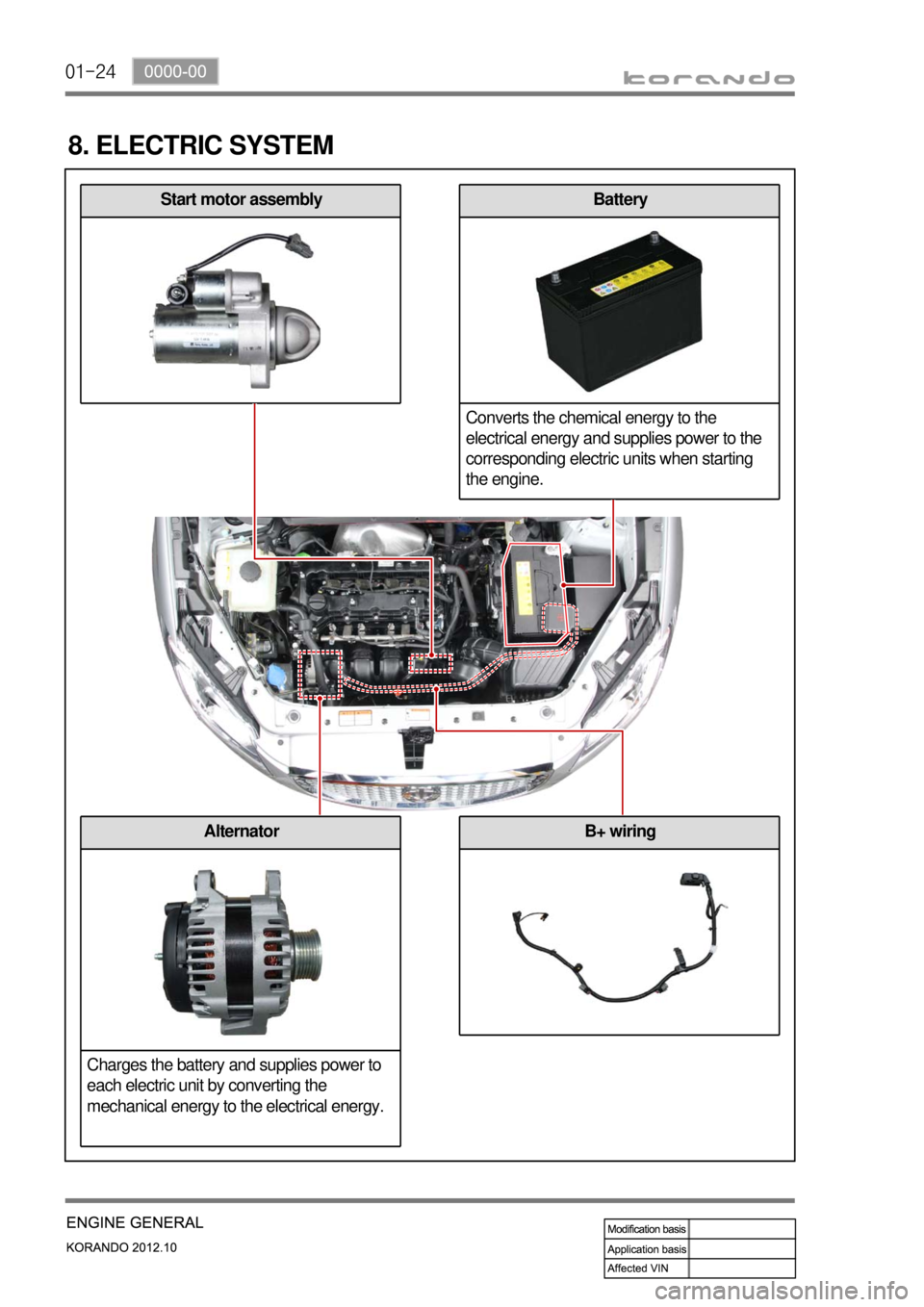
8. ELECTRIC SYSTEM
Start motor assemblyBattery
Converts the chemical energy to the
electrical energy and supplies power to the
corresponding electric units when starting
the engine.
B+ wiringAlternator
Charges the battery and supplies power to
each electric unit by converting the
mechanical energy to the electrical energy.