Glow plug SSANGYONG KORANDO 2012 Service Manual
[x] Cancel search | Manufacturer: SSANGYONG, Model Year: 2012, Model line: KORANDO, Model: SSANGYONG KORANDO 2012Pages: 1082, PDF Size: 96.1 MB
Page 113 of 1082
02-6
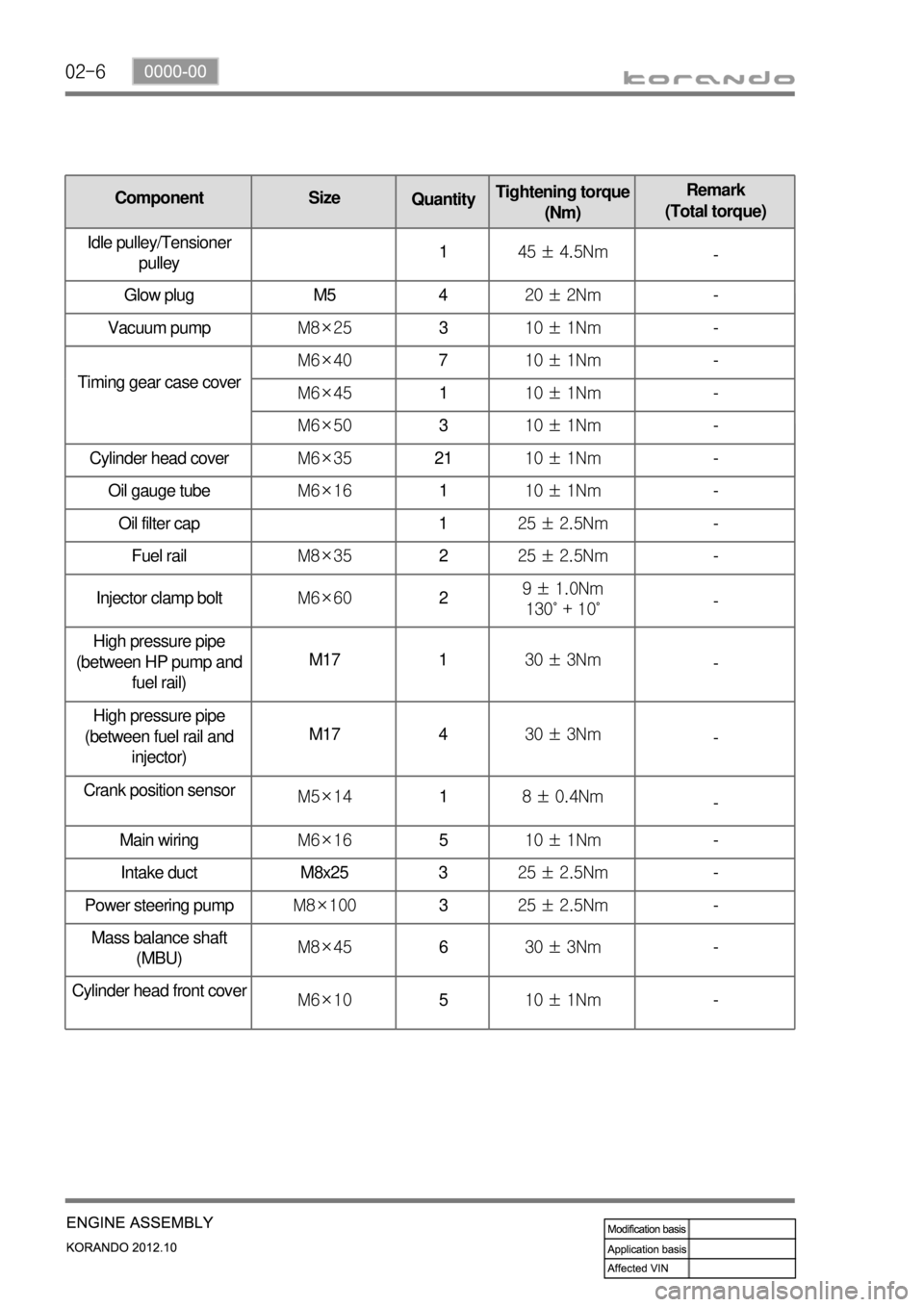
품명 규격 볼트
수량규정토오크(Nm) 비고
(총 토오크)
Oil gauge tubeM6×16110 ± 1Nm-
Oil filter cap 125 ± 2.5Nm-
Fuel railM8×35225 ± 2.5Nm-
Injector clamp boltM6×6029 ± 1.0Nm
130˚ + 10˚-
High pressure pipe
(between HP pump and
fuel rail)M17 130 ± 3Nm
-
High pressure pipe
(between fuel rail and
injector)M17 430 ± 3Nm
-
Crank position sensor
M5×1418 ± 0.4Nm
-
Main wiringM6×16510 ± 1Nm-
Intake duct M8x25 325 ± 2.5Nm-
Power steering pumpM8×100325 ± 2.5Nm-
Mass balance shaft
(MBU)M8×45630 ± 3Nm-
Cylinder head front cove
rM6×10510 ± 1Nm-
품명 규격볼트
수량규정토오크(Nm)비고
(총 토오크)
Timing gear case coverM6×40710 ± 1Nm-
M6×45110 ± 1Nm-
M6×50310 ± 1Nm-
Cylinder head coverM6×352110 ± 1Nm-
Component Size
QuantityTightening torque
(Nm)Remark
(Total torque)
Idle pulley/Tensioner
pulley145 ± 4.5Nm
-
Glow plug M5 420 ± 2Nm-
Vacuum pumpM8×25310 ± 1Nm-
Page 227 of 1082

10-31413-00
1. SPECIFICATION
Description Specification
Glow plug Rated voltage 4.4 V
Maximum temperature1100°C
Operating temperature1080 to 1100°C
Glow plug control unit EMS operating voltage 6 to 16 V
Operating temperature-40°C to 110°C
Dark current Max. 1 mA
Page 228 of 1082

10-4
GCU (Glow plug Control Unit)
2. TIGHTENING TORQUE
No. Name Tightening torque
1 Glow plug 15 ± 1.5 Nm
2 Glow plug control unit bolt 10 ± 1.0 Nm
Glow plug
Page 229 of 1082
10-51413-00
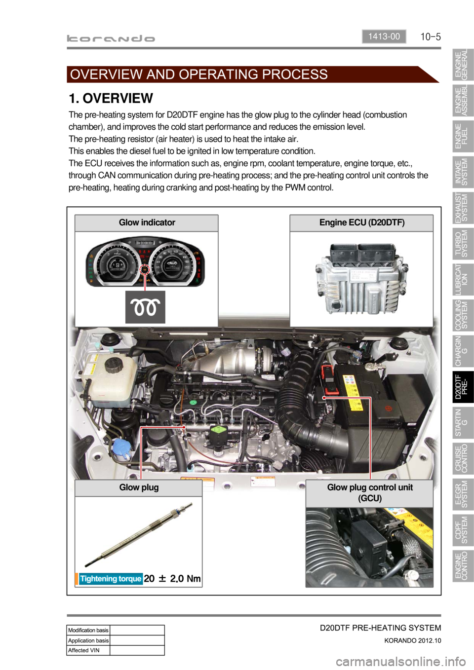
1. OVERVIEW
The pre-heating system for D20DTF engine has the glow plug to the cylinder head (combustion
chamber), and improves the cold start performance and reduces the emission level.
The pre-heating resistor (air heater) is used to heat the intake air.
This enables the diesel fuel to be ignited in low temperature condition.
The ECU receives the information such as, engine rpm, coolant temperature, engine torque, etc.,
through CAN communication during pre-heating process; and the pre-heating control unit controls the
pre-heating, heating during cranking and post-heating by the PWM control.
Glow plugGlow plug control unit
(GCU)
Glow indicatorEngine ECU (D20DTF)
Page 230 of 1082
10-6
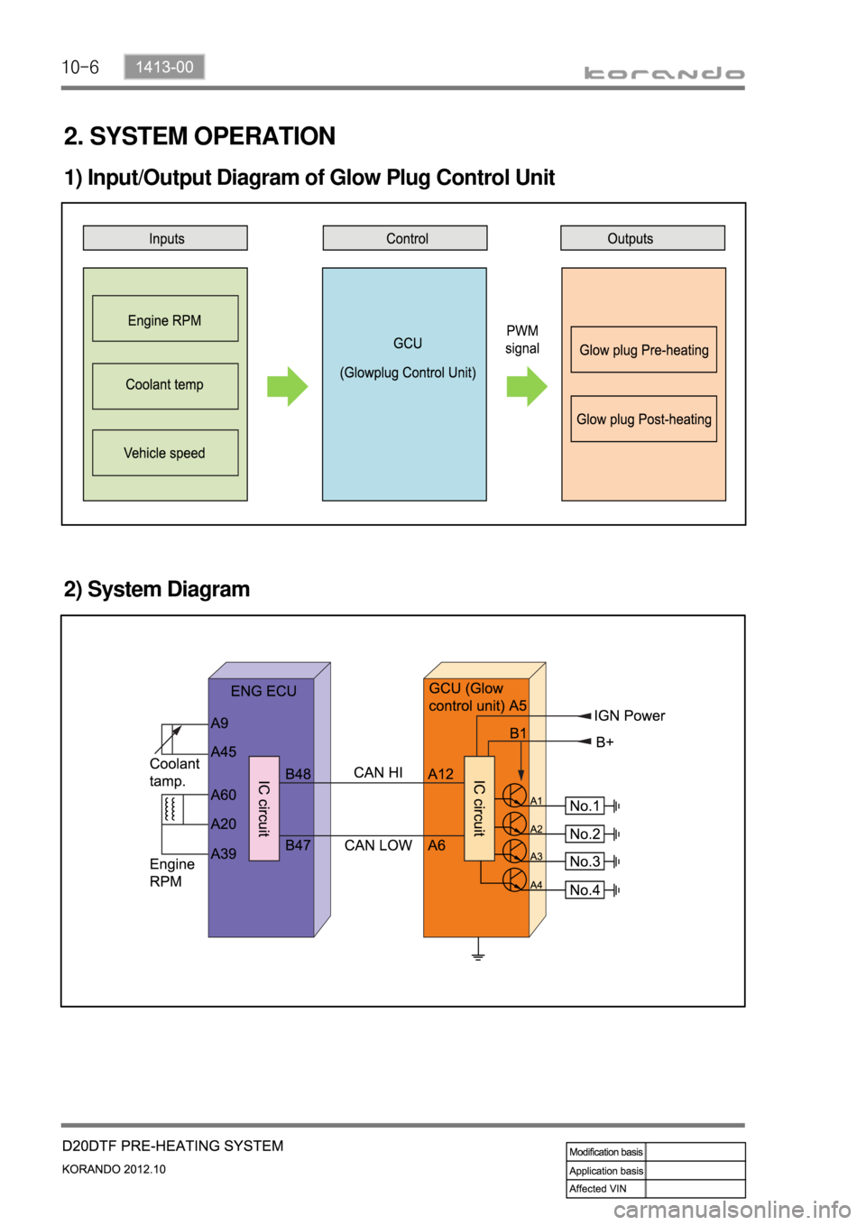
2. SYSTEM OPERATION
1) Input/Output Diagram of Glow Plug Control Unit
2) System Diagram
Page 234 of 1082
10-10
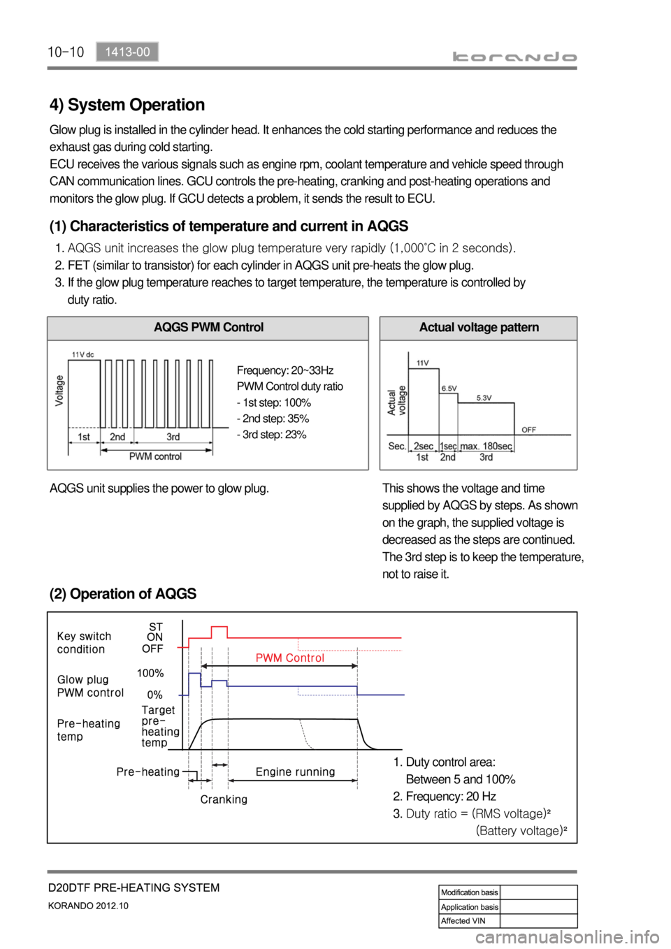
4) System Operation
Glow plug is installed in the cylinder head. It enhances the cold starting performance and reduces the
exhaust gas during cold starting.
ECU receives the various signals such as engine rpm, coolant temperature and vehicle speed through
CAN communication lines. GCU controls the pre-heating, cranking and post-heating operations and
monitors the glow plug. If GCU detects a problem, it sends the result to ECU.
(2) Operation of AQGS
Duty control area:
Between 5 and 100%
Frequency: 20 Hz
Duty ratio = (RMS voltage)²
(Battery voltage)² 1.
2.
3.
(1) Characteristics of temperature and current in AQGS
AQGS unit increases the glow plug temperature very rapidly (1,000˚C in 2 seconds).
FET (similar to transistor) for each cylinder in AQGS unit pre-heats the glow plug.
If the glow plug temperature reaches to target temperature, the temperature is controlled by
duty ratio. 1.
2.
3.
AQGS PWM ControlActual voltage pattern
AQGS unit supplies the power to glow plug. This shows the voltage and time
supplied by AQGS by steps. As shown
on the graph, the supplied voltage is
decreased as the steps are continued.
The 3rd step is to keep the temperature,
not to raise it.
Frequency: 20~33Hz
PWM Control duty ratio
- 1st step: 100%
- 2nd step: 35%
- 3rd step: 23%
Page 235 of 1082

10-111413-00
(3) Operating Steps
Pre-Glow: Step 1 ▶
If normal communication with the ECU is established 2 seconds after the power is supplied to the IGN
terminal from the battery, the GCU supplies the battery power to raise the temperature of the glow plug
<009b0096004700580057005700570b450047008900a00047009b008f008c004700970099008c008f008c0088009b00900095008e00470099008c0098009c008c009a009b0047008d0099009600940047009b008f008c0047008c0095008e00900095008c00
47006c006a007c00470089008c008d00960099008c0047009a>tarting.
- The time for pre-heating is controlled by the ECU.
If the input voltage (VB) is 11.5 V or less, GCU supplies the battery voltage for preheating time (T1).
If the input voltage (VB) is greater than 11.5 V, GCU supplies the voltage of 11.5 V for preheating time
(T1). -
-
The preheating time may vary according to the conditions.
Input voltage
VB (V)Pre-heating time T1
(sec)
6 8.27
7 5.8
8 4.1
9 3.15
10 2.4
11 1.95
≥ 11.5 1.9
Page 236 of 1082

10-12
During cranking: Step 2 and step 3 ▶
Step 2: If the ECU receives the cranking signal after pre-heating (step 1), the GCU supplies the
<009d00960093009b0088008e008c00470096008d0047005d0055005f0047007d0047008d00960099004700580047009a008c008a0047009b00960047009900880090009a008c0047009b008f008c0047009b008c00940097008c00990088009b009c009900
8c0047009b00960047005800530058005700570b450055>
Step 3: The GCU supplies the voltage of 5.1 V to keep the temperature at 1,000°C. 1.
2.
Under fixed temperature: The AQGS unit supplies power for 30 seconds (Step 1 + Step 3) if no
cranking signal is received after the step 1.
During cranking: The step 3 is started after the step 2. *
*
Post-glow: Step 4: ▶
The post-heating is for reducing HC/CO after the engine is started. If the time for post-heating exceeds
180 sec., the GCU unit cuts off the power to each glow plug even if there is preheating request from the
engine ECU.
Emergency glow ▶
If no CAN signal is received for 4 seconds from the engine ECU after the IGN ON signal is input, the
GCU performs emergency preheating (Step 3) for 30 seconds.
Page 280 of 1082

15-4
Rear exhaust gas temp.
sensor
Electronic throttle
bodyT-MAP sensor
(Temp.+Pres.)
Injector (C3I)
1. MAJOR COMPONENT
Oxygen sensorFront exhaust gas temp.
sensor
Camshaft position
sensor
Glow plug
Variable swirl valve
Knock sensor (2)Oil level sensor
Page 281 of 1082
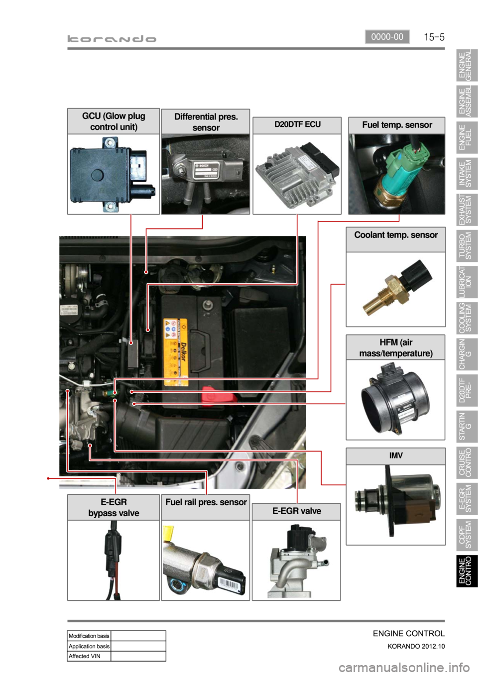
15-50000-00
HFM (air
mass/temperature)
Fuel temp. sensor
GCU (Glow plug
control unit)Differential pres.
sensorD20DTF ECU
Coolant temp. sensor
IMV
E-EGR
bypass valve
E-EGR valve
Fuel rail pres. sensor