heater SSANGYONG KORANDO 2013 User Guide
[x] Cancel search | Manufacturer: SSANGYONG, Model Year: 2013, Model line: KORANDO, Model: SSANGYONG KORANDO 2013Pages: 1336, PDF Size: 92.18 MB
Page 437 of 1336
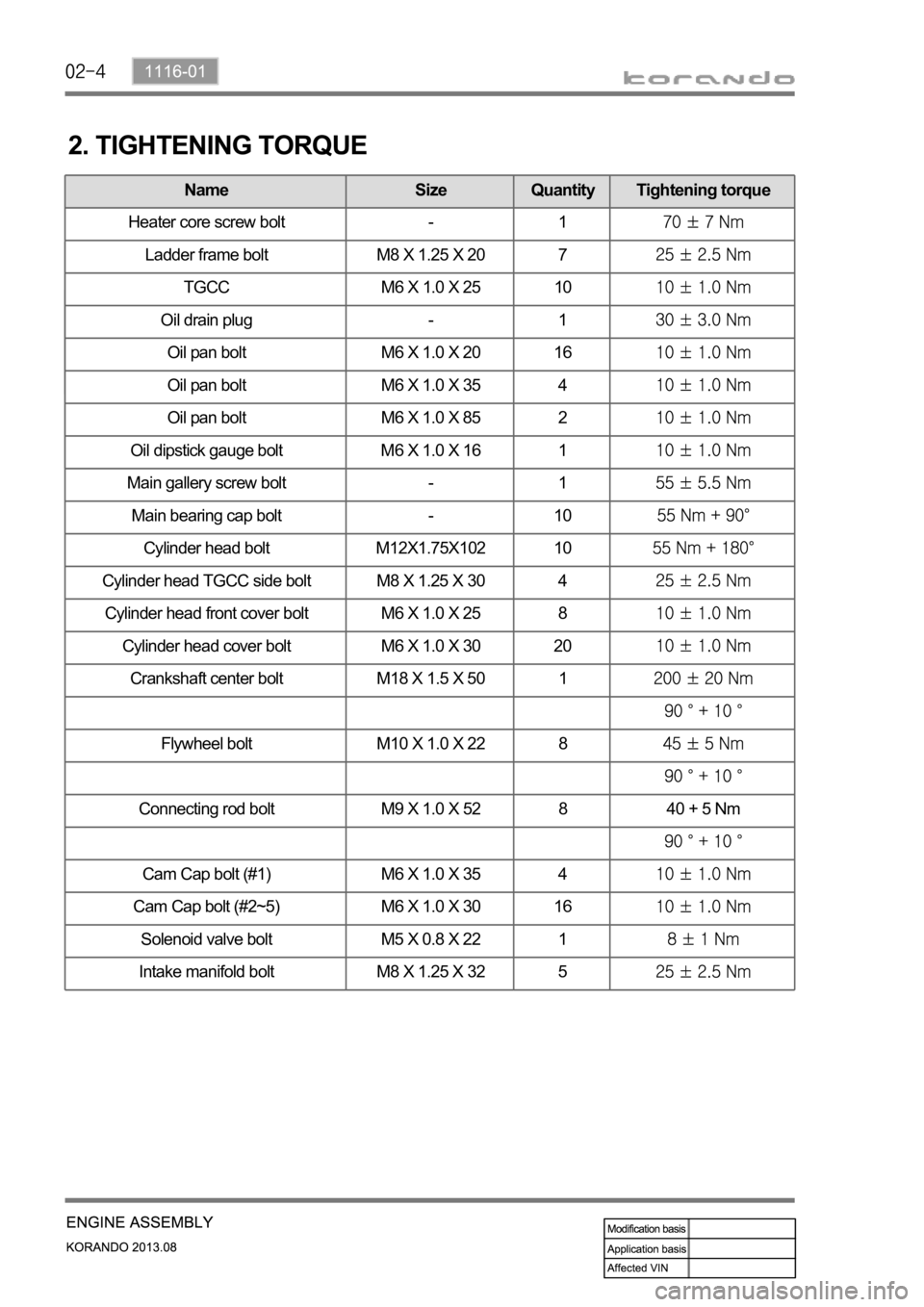
Name Size Quantity Tightening torque
Oil pan bolt M6 X 1.0 X 20 16
Oil pan bolt M6 X 1.0 X 35 4
Oil pan bolt M6 X 1.0 X 85 2
Oil dipstick gauge bolt M6 X 1.0 X 16 1
Camshaft cap M6 X 1.0 X 30 20
Main gallery screw bolt - 1
Main bearing cap bolt - 10
Cylinder head bolt M12X1.75X102 10
Cylinder head TGCC side bolt M8 X 1.25 X 30 4
Cylinder head front cover bolt M6 X 1.0 X 25 8
Cylinder head cover bolt M6 X 1.0 X 30 20
Crankshaft center bolt M18 X 1.5 X 50 1
Flywheel bolt M10 X 1.0 X 22 8
Connecting rod bolt M9 X 1.0 X 52 8 40 + 5 Nm
Cam Cap bolt (#1) M6 X 1.0 X 35 4
Cam Cap bolt (#2~5) M6 X 1.0 X 30 16
Solenoid valve bolt M5 X 0.8 X 22 1
Intake manifold bolt M8 X 1.25 X 32 5
2. TIGHTENING TORQUE
Name Size Quantity Tightening torque
Heater core screw bolt - 1
Ladder frame bolt M8 X 1.25 X 20 7
TGCC M6 X 1.0 X 25 10
Oil drain plug - 1
Oil pan bolt M6 X 1.0 X 20 16
Oil pan bolt M6 X 1.0 X 35 4
Oil pan bolt M6 X 1.0 X 85 2
Oil dipstick gauge bolt M6 X 1.0 X 16 1
Page 514 of 1336
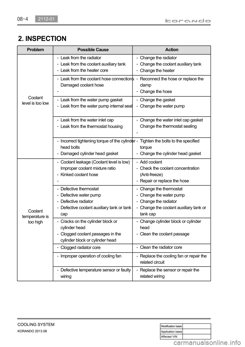
Problem Possible Cause Action
Coolant
level is too low
Coolant
temperature is
too high
2. INSPECTION
Leak from the radiator
Leak from the coolant auxiliary tank
Leak from the heater core -
-
-
Leak from the water inlet cap
Leak from the thermostat housing -
-Reconnect the hose or replace the
clamp
Change the hose -
- Leak from the coolant hose connections
Damaged coolant hose -
-
Change the gasket
Change the water pump -
- Leak from the water pump gasket
Leak from the water pump internal seal -
-
Tighten the bolts to the specified
torque
Change the cylinder head gasket -
- Incorrect tightening torque of the cylinder
head bolts
Damaged cylinder head gasket -
-Change the water inlet cap gasket
Change the thermostat sealing -
-
Coolant leakage (Coolant level is low)
Improper coolant mixture ratio
Kinked coolant hose -
-
-Add coolant
Check the coolant concentration
(Anti-freeze)
Repair or replace the hose -
-
-
Defective thermostat
Defective water pump
Defective radiator
Defective coolant auxiliary tank or tank
cap -
-
-
-Change the thermostat
Change the water pump
Change the radiator
Change the coolant auxiliary tank or
tank cap -
-
-
-Change the radiator
Change the coolant auxiliary tank
Change the heater -
-
-
Cracks on the cylinder block or
cylinder head
Clogged coolant passages in the
cylinder block or cylinder head -
-Change cylinder block or cylinder
head
Clean the coolant passage -
-
Clogged radiator core -
Replace the sensor or repair the
related wiring - Improper operation of cooling fan -Clean the radiator core -
Defective temperature sensor or faulty
wiring -Replace the cooling fan or repair the
related circuit -
Page 524 of 1336

3. COOLANT FLOW DIAGRAM
Heater
return Water pump
Thermostat
Bypass
Page 525 of 1336

2112-01
Coolant outlet port
to radiator
to water pump (bypass)
to cabin heater
to coolant reservoir
Coolant temperature
sensor mountinh boss
from cylinder head
Gasket A:
B:
C:
D:
E:
F:
G:
Coolant outlet port
Page 632 of 1336
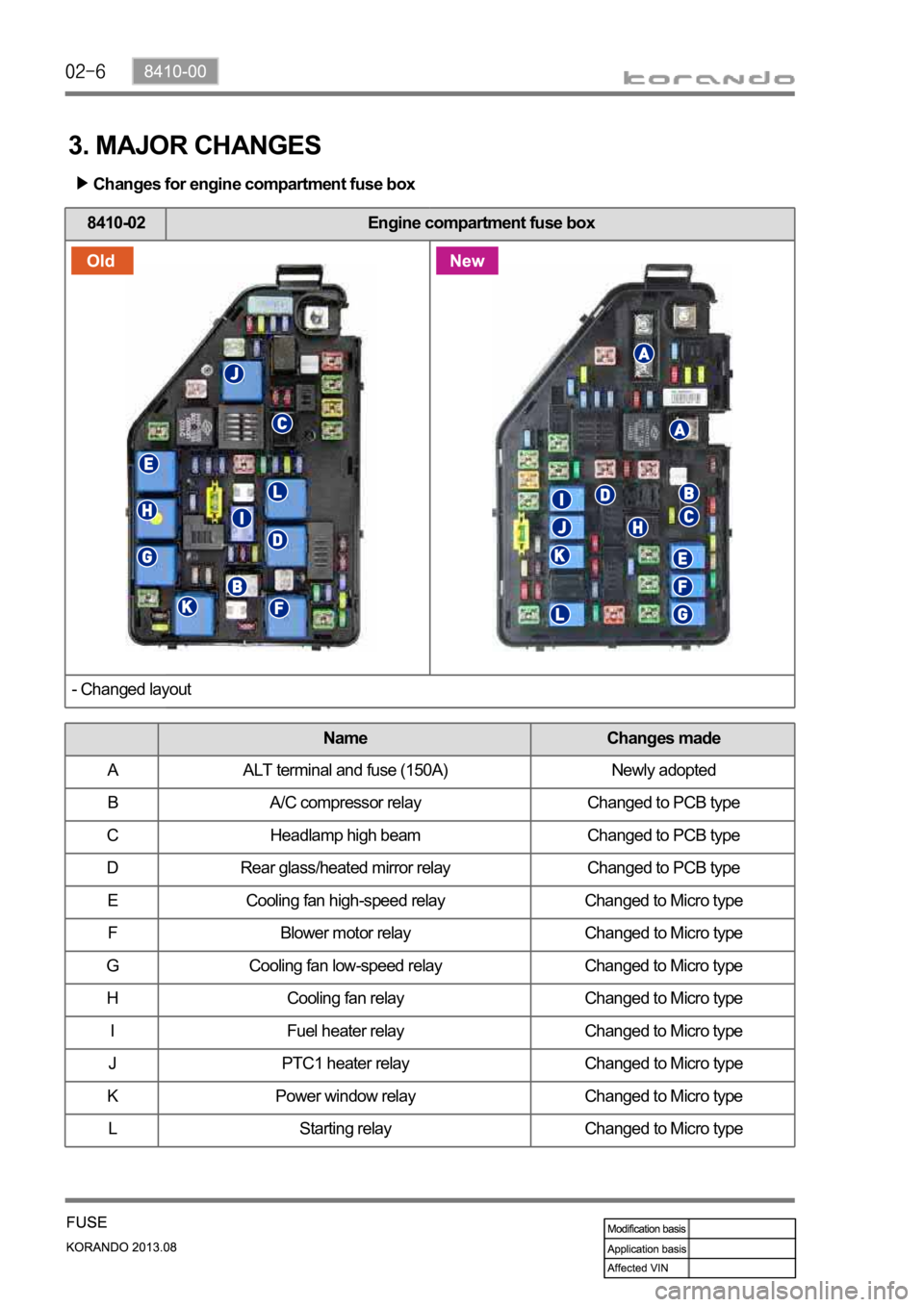
3. MAJOR CHANGES
Changes for engine compartment fuse box
8410-02 Engine compartment fuse box
- Changed layout
Name Changes made
A ALT terminal and fuse (150A) Newly adopted
B A/C compressor relay Changed to PCB type
C Headlamp high beam Changed to PCB type
D Rear glass/heated mirror relay Changed to PCB type
E Cooling fan high-speed relay Changed to Micro type
F Blower motor relay Changed to Micro type
G Cooling fan low-speed relay Changed to Micro type
H Cooling fan relay Changed to Micro type
I Fuel heater relay Changed to Micro type
J PTC1 heater relay Changed to Micro type
K Power window relay Changed to Micro type
L Starting relay Changed to Micro type
Page 843 of 1336
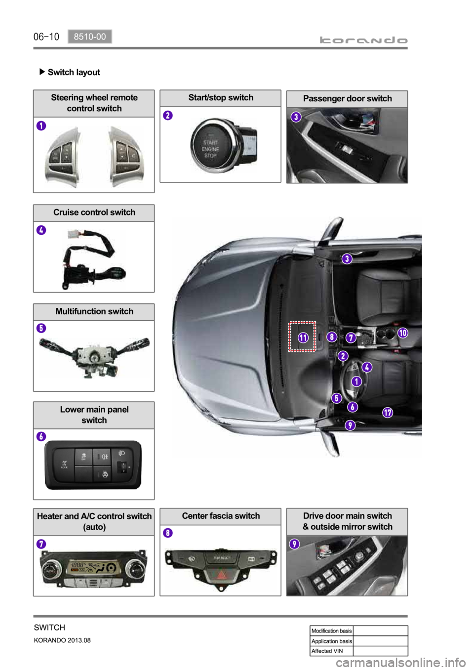
Drive door main switch
& outside mirror switchHeater and A/C control switch
(auto)
Start/stop switchSteering wheel remote
control switch
Center fascia switch
Passenger door switch
Lower main panel
switch
Cruise control switch
Multifunction switch
Switch layout
Page 854 of 1336
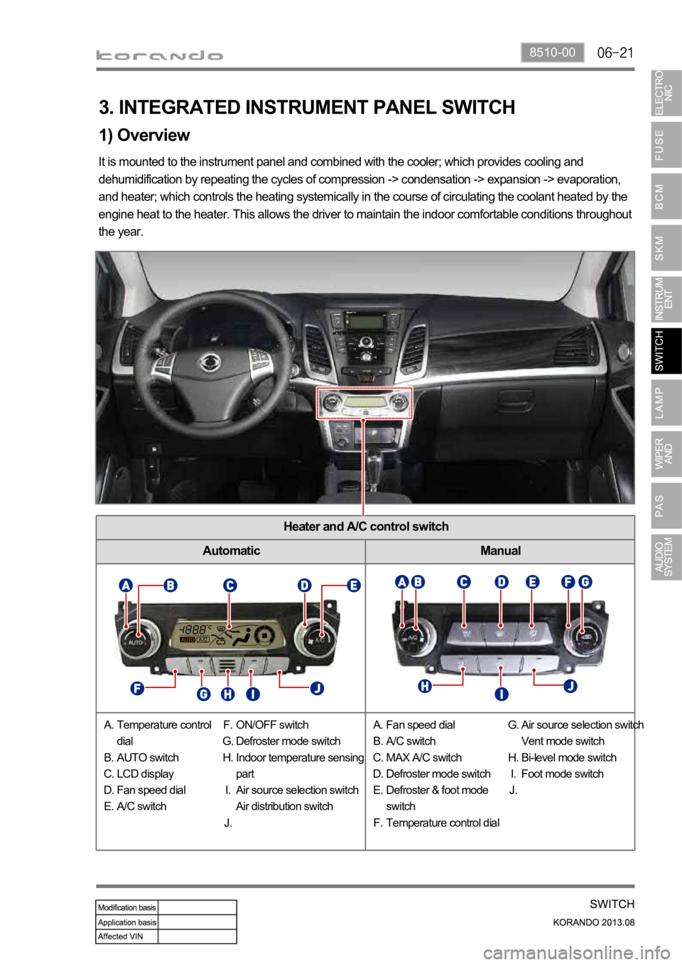
8510-00
Heater and A/C control switch
Automatic Manual
1) Overview
3. INTEGRATED INSTRUMENT PANEL SWITCH
It is mounted to the instrument panel and combined with the cooler; which provides cooling and
dehumidification by repeating the cycles of compression -> condensation -> expansion -> evaporation,
and heater; which controls the heating systemically in the course of circulating the coolant heated by the
engine heat to the heater. This allows the driver to maintain the indoor comfortable conditions throughout
the year.
Temperature control
dial
AUTO switch
LCD display
Fan speed dial
A/C switch A.
B.
C.
D.
E.ON/OFF switch
Defroster mode switch
Indoor temperature sensing
part
Air source selection switch
Air distribution switch F.
G.
H.
I.
J.Fan speed dial
A/C switch
MAX A/C switch
Defroster mode switch
Defroster & foot mode
switch
Temperature control dial A.
B.
C.
D.
E.
F.Air source selection switch
Vent mode switch
Bi-level mode switch
Foot mode switch G.
H.
I.
J.
Page 1189 of 1336

6810-00
1. SPECIFICATIONS
Unit Item Specification
Heater
200 x 168.5 x 23.5
Capacity (kcal/h) 4,800
Evaporator
254.8 x 196.7 x 60
Capacity (kcal/h) 4,700
Blower motor Supply power (W) 240 + 10% Max (at 12 V)
Fan speed (rpm)
PTC Supply power 1 kW
Condenser
588 x 455 x 16 (2,625)
Capacity (kcal/h) 12,000
Capacity of receiver drier 250 cc
Compressor Volume 170 cc/rev
Diameter of pulley
Max. continuous speed 8,000 rpm
Voltage DC 12 V
Current consumption 2.2 A
Heater & A/C
control assembly
(FATC)Rated voltage DC 13.5 V
Operating voltage DC 9 V to 16 V
Operating temperature
Max. current consumption 2.5 A
Dark current 1.1 mA
Button switch Type Push type (self-return)
Operating force
Temperature & air
distribution switchType Dial type
Rotation angle
Page 1190 of 1336
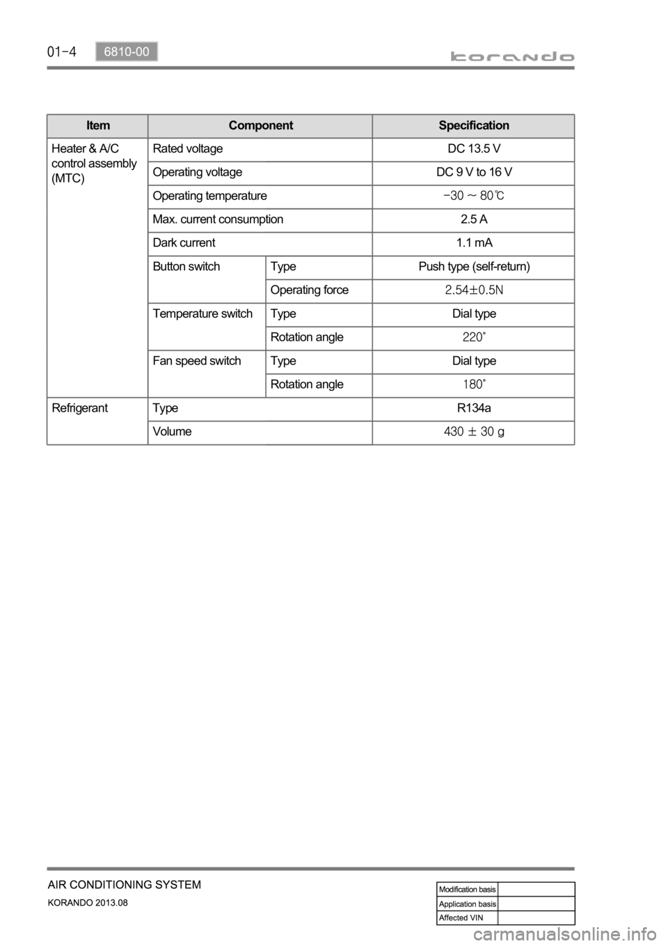
Item Component Specification
Heater & A/C
control assembly
(MTC)Rated voltage DC 13.5 V
Operating voltage DC 9 V to 16 V
Operating temperature
Max. current consumption 2.5 A
Dark current 1.1 mA
Button switch Type Push type (self-return)
Operating force
Temperature switch Type Dial type
Rotation angle
Fan speed switch Type Dial type
Rotation angle
Refrigerant Type R134a
Volume
Page 1191 of 1336

6810-00
Heater & A/C control assembly
Heater and A/C control assembly design and switch arrangement changed
- Digital display (LCD display) with FATC used
- Push button type switch used (self-return type)
2. MAJOR CHANGES
Change of air conditioner pipe
With MTC
With FATC
With MTC
With FATC
Changes in heater and control assembly
Liquid and suction pipe
Liquid and suction pipe route changed due to change of headlamp mounting bracket