power steering SSANGYONG KORANDO 2013 User Guide
[x] Cancel search | Manufacturer: SSANGYONG, Model Year: 2013, Model line: KORANDO, Model: SSANGYONG KORANDO 2013Pages: 1336, PDF Size: 92.18 MB
Page 442 of 1336
1337-04
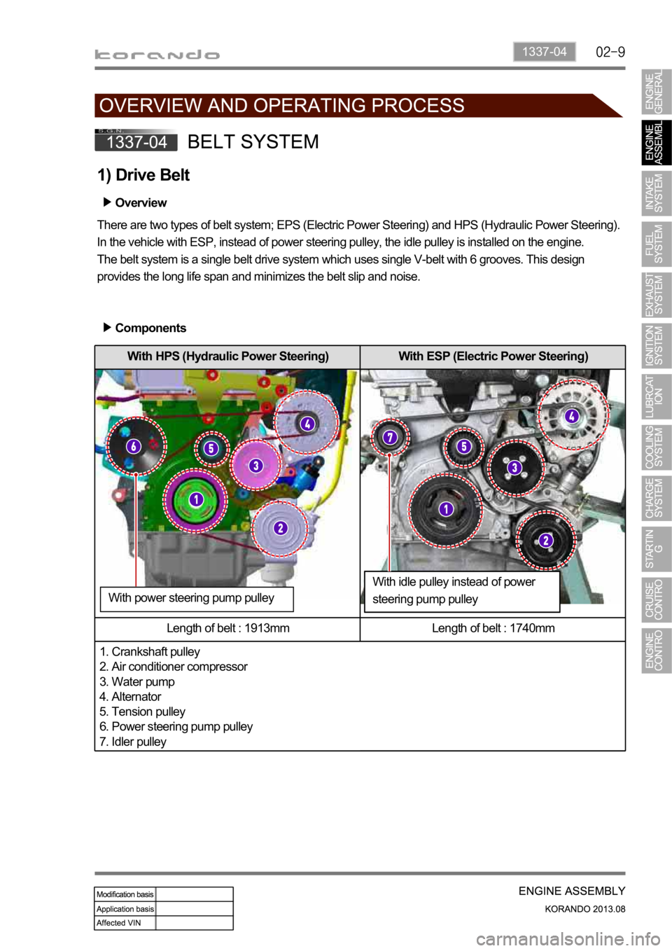
With HPS (Hydraulic Power Steering) With ESP (Electric Power Steering)
Length of belt : 1913mm Length of belt : 1740mm
1. Crankshaft pulley
2. Air conditioner compressor
3. Water pump
4. Alternator
5. Tension pulley
6. Power steering pump pulley
7. Idler pulley
1) Drive Belt
Overview
There are two types of belt system; EPS (Electric Power Steering) and HPS (Hydraulic Power Steering).
In the vehicle with ESP, instead of power steering pulley, the idle pulley is installed on the engine.
The belt system is a single belt drive system which uses single V-belt with 6 grooves. This design
provides the long life span and minimizes the belt slip and noise.
Components
With idle pulley instead of power
steering pump pulley With power steering pump pulley
Page 571 of 1336
0000-00
(2) Warm-up Control Function
Low voltage
If low voltage is detected by the ECU, the idle speed increases up to 100 rpm selectively under the
driving mode until the ignition switch is turned off. Idle speed control
The idle speed is controlled according to the fuel/air mixture when the engine load is changed, the
power steering wheel is turned to its end, the selector lever is in the "D" position and the A/C compresso
r
is in operation. It is also controlled according to the charge level during the purge control operation.
Ignition timing
The idle speed is controlled according to the fuel/air mixture when the engine load is changed, The
Air conditioner compressor operation
The air conditioner control unit sends the air conditioner operation signal to the ECU to increase the
throttle valve opening amount in order to prevent reduction of the engine speed when the air conditioner
compressor is in operation at idling.
(3) Warm-up Control Operating Conditions
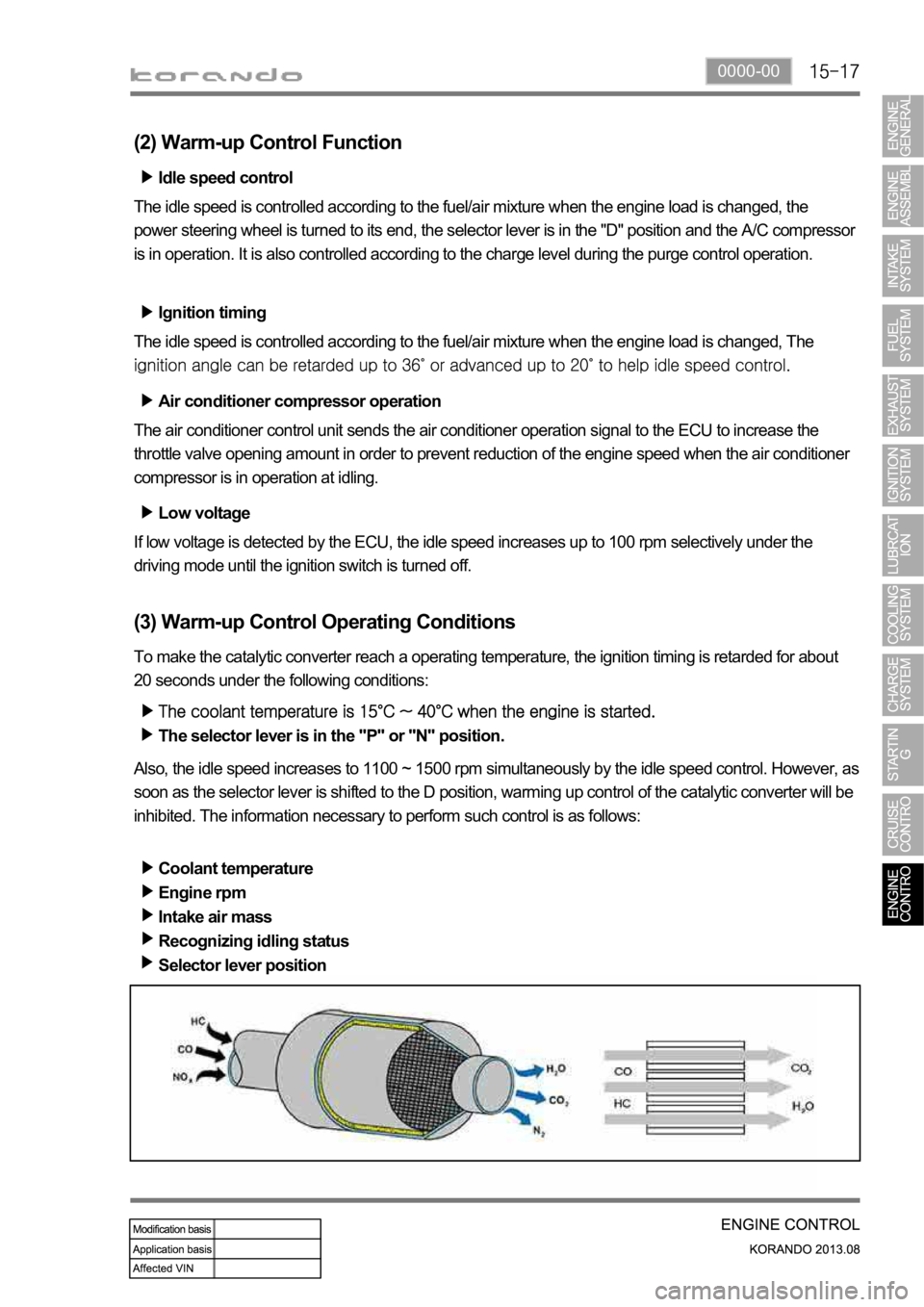
To make the catalytic converter reach a operating temperature, the ignition timing is retarded for about
20 seconds under the following conditions:
The selector lever is in the "P" or "N" position.
Also, the idle speed increases to 1100 ~ 1500 rpm simultaneously by the idle speed control. However, as
soon as the selector lever is shifted to the D position, warming up control of the catalytic converter will be
inhibited. The information necessary to perform such control is as follows:
Coolant temperature
Engine rpm
Intake air mass
Recognizing idling status
Selector lever position
Page 577 of 1336
0000-00
8) CAN Configuration (P-CAN/B-CAN)
(1) CAN Configuration (P-CAN/B-CAN)
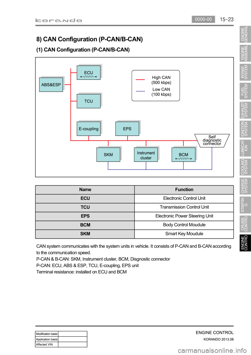
Name Function
ECUElectronic Control Unit
TCUTransmission Control Unit
EPSElectronic Power Steering Unit
BCMBody Control Moudule
SKMSmart Key Moudule
CAN system communicates with the system units in vehicle. It consists of P-CAN and B-CAN according
to the communication speed.
P-CAN & B-CAN: SKM, Instrument cluster, BCM, Disgnostic connector
P-CAN: ECU, ABS & ESP, TCU, E-coupling, EPS unit
Terminal resistance: installed on ECU and BCM
Page 626 of 1336
5. CAN COMMUNICATION CONFIGURATION
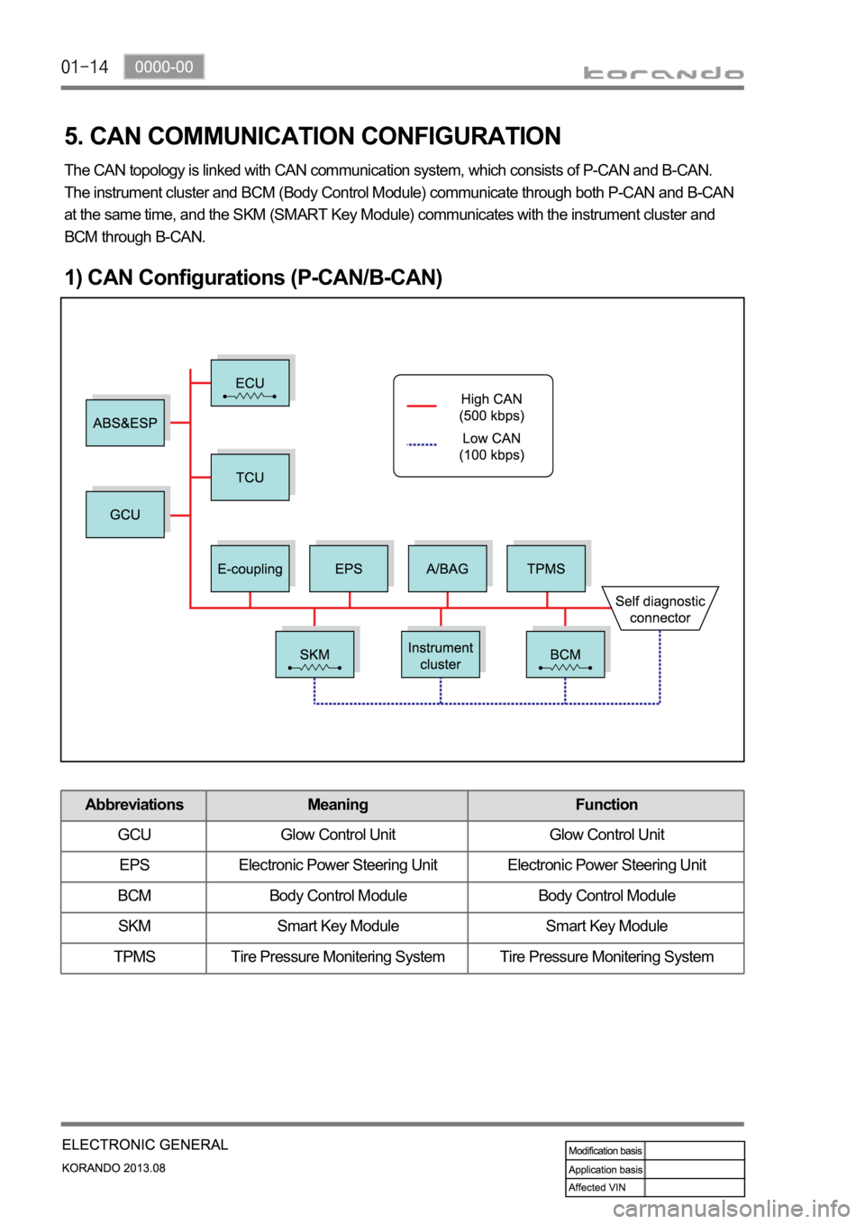
The CAN topology is linked with CAN communication system, which consists of P-CAN and B-CAN.
The instrument cluster and BCM (Body Control Module) communicate through both P-CAN and B-CAN
at the same time, and the SKM (SMART Key Module) communicates with the instrument cluster and
BCM through B-CAN.
1) CAN Configurations (P-CAN/B-CAN)
Abbreviations Meaning Function
GCU Glow Control Unit Glow Control Unit
EPS Electronic Power Steering Unit Electronic Power Steering Unit
BCM Body Control Module Body Control Module
SKM Smart Key Module Smart Key Module
TPMS Tire Pressure Monitering System Tire Pressure Monitering System
Page 776 of 1336
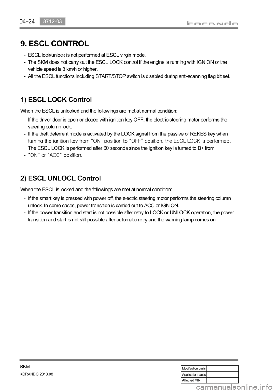
9. ESCL CONTROL
ESCL lock/unlock is not performed at ESCL virgin mode.
The SKM does not carry out the ESCL LOCK control if the engine is running with IGN ON or the
vehicle speed is 3 km/h or higher.
All the ESCL functions including START/STOP switch is disabled during anti-scanning flag bit set. -
-
-
If the smart key is pressed with power off, the electric steering motor performs the steering column
unlock. In some cases, power transition is carried out to ACC or IGN ON.
If the power transition and start is not possible after retry to LOCK or UNLOCK operation, the power
transition and start is not still possible after automatic retry and the warning lamp comes on. -
-
1) ESCL LOCK Control
When the ESCL is unlocked and the followings are met at normal condition:
If the driver door is open or closed with ignition key OFF, the electric steering motor performs the
steering column lock.
If the theft deterrent mode is activated by the LOCK signal from the passive or REKES key when
The ESCL LOCK is performed after 60 seconds since the ignition key is turned to B+ from
-
-
-
2) ESCL UNLOCL Control
When the ESCL is locked and the followings are met at normal condition:
Page 837 of 1336
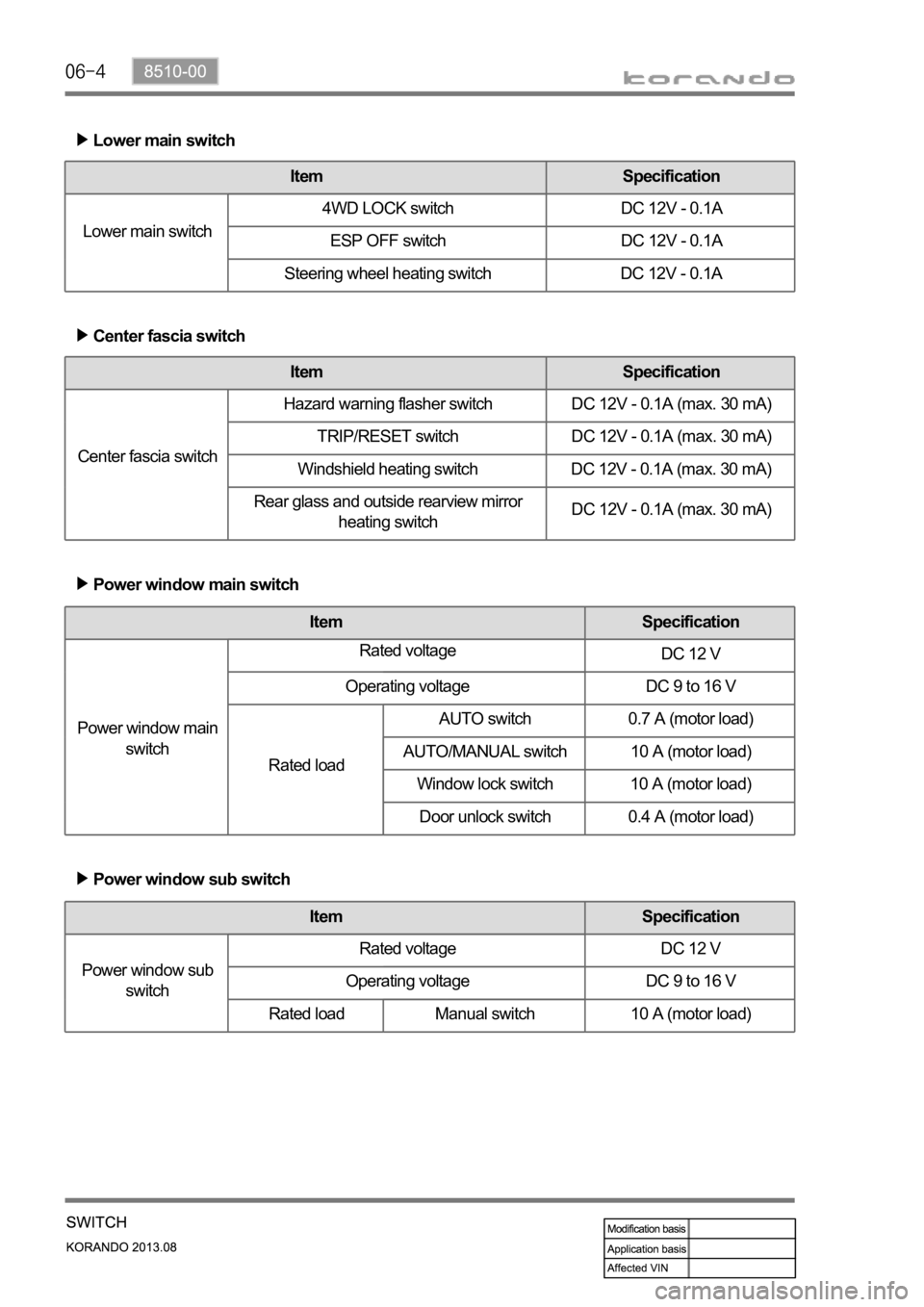
Lower main switch
Item Specification
Lower main switch4WD LOCK switch DC 12V - 0.1A
ESP OFF switch DC 12V - 0.1A
Steering wheel heating switch DC 12V - 0.1A
Center fascia switch
Item Specification
Center fascia switchHazard warning flasher switch DC 12V - 0.1A (max. 30 mA)
TRIP/RESET switch DC 12V - 0.1A (max. 30 mA)
Windshield heating switch DC 12V - 0.1A (max. 30 mA)
Rear glass and outside rearview mirror
heating switchDC 12V - 0.1A (max. 30 mA)
Power window main switch
Item Specification
Power window main
switchRated voltage
DC 12 V
Operating voltage DC 9 to 16 V
Rated loadAUTO switch 0.7 A (motor load)
AUTO/MANUAL switch 10 A (motor load)
Window lock switch 10 A (motor load)
Door unlock switch 0.4 A (motor load)
Power window sub switch
Item Specification
Power window sub
switchRated voltage DC 12 V
Operating voltage DC 9 to 16 V
Rated load Manual switch 10 A (motor load)
Page 877 of 1336
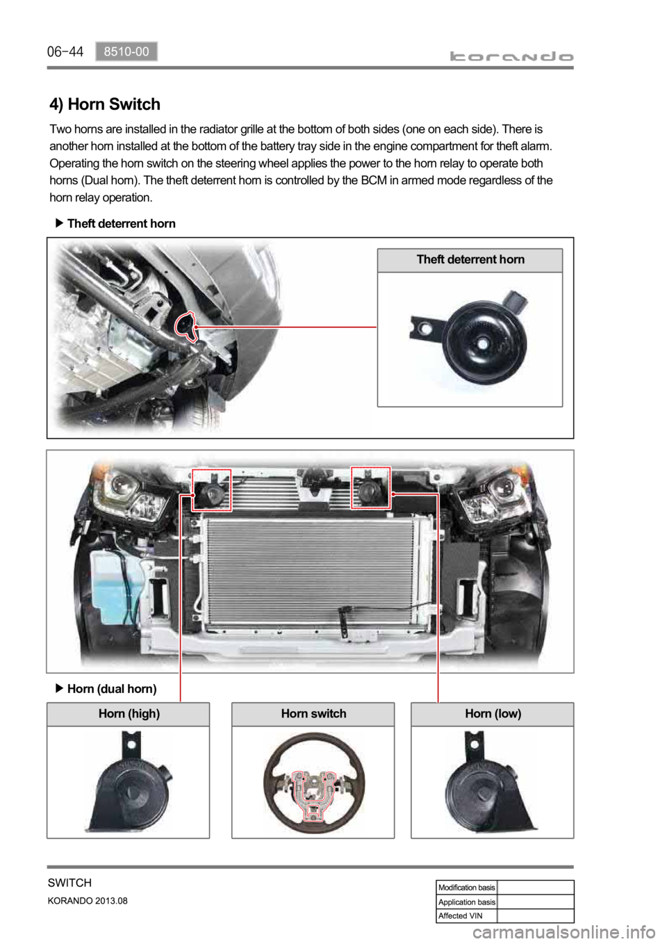
Horn (high) Horn (low)
Theft deterrent horn
Theft deterrent horn
4) Horn Switch
Two horns are installed in the radiator grille at the bottom of both sides (one on each side). There is
another horn installed at the bottom of the battery tray side in the engine compartment for theft alarm.
Operating the horn switch on the steering wheel applies the power to the horn relay to operate both
horns (Dual horn). The theft deterrent horn is controlled by the BCM in armed mode regardless of the
horn relay operation.
Horn (dual horn)
Horn switch
Page 984 of 1336
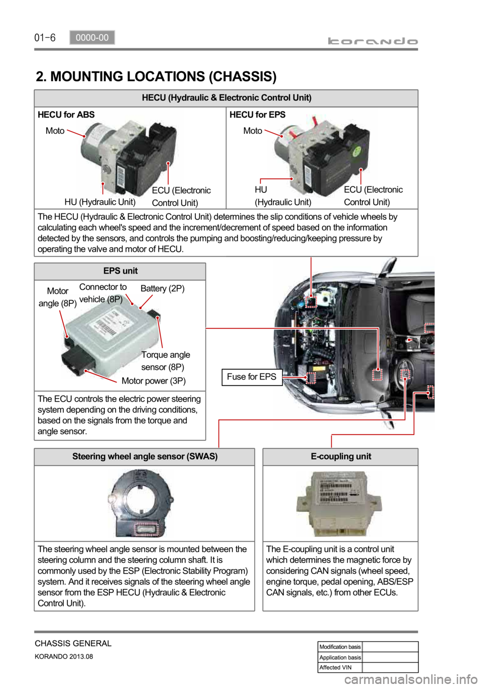
HECU (Hydraulic & Electronic Control Unit)
HECU for ABS HECU for EPS
The HECU (Hydraulic & Electronic Control Unit) determines the slip conditions of vehicle wheels by
calculating each wheel's speed and the increment/decrement of speed based on the information
detected by the sensors, and controls the pumping and boosting/reducing/keeping pressure by
operating the valve and motor of HECU.
2. MOUNTING LOCATIONS (CHASSIS)
Moto
HU (Hydraulic Unit) ECU (Electronic
Control Unit) Moto
HU
(Hydraulic Unit) ECU (Electronic
Control Unit)
Motor
angle (8P)
Motor power (3P)Torque angle
sensor (8P) Battery (2P) Connector to
vehicle (8P)
Fuse for EPS
Steering wheel angle sensor (SWAS)
The steering wheel angle sensor is mounted between the
steering column and the steering column shaft. It is
commonly used by the ESP (Electronic Stability Program)
system. And it receives signals of the steering wheel angle
sensor from the ESP HECU (Hydraulic & Electronic
Control Unit).
EPS unit
The ECU controls the electric power steering
system depending on the driving conditions,
based on the signals from the torque and
angle sensor.
E-coupling unit
The E-coupling unit is a control unit
which determines the magnetic force by
considering CAN signals (wheel speed,
engine torque, pedal opening, ABS/ESP
CAN signals, etc.) from other ECUs.
Page 985 of 1336
0000-00
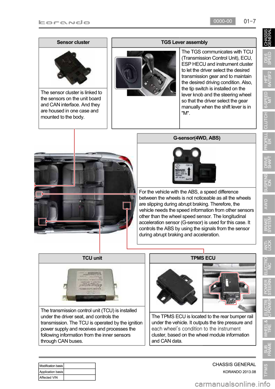
TPMS ECU
The TPMS ECU is located to the rear bumper rail
under the vehicle. It outputs the tire pressure and
cluster, based on the wheel module information
and CAN data.
G-sensor(4WD, ABS)
For the vehicle with the ABS, a speed difference
between the wheels is not noticeable as all the wheels
are slipping during abrupt braking. Therefore, the
vehicle needs the speed information from other sensors
other than the wheel speed sensor. The longitudinal
acceleration sensor (G-sensor) is used for this case. It
controls the ABS by using the signals from the sensor
during abrupt braking and acceleration.
TCU unit
The transmission control unit (TCU) is installed
under the driver seat, and controls the
transmission. The TCU is operated by the ignition
power supply and receives and processes the
following information from the inner sensors
through CAN buses.
TGS Lever assembly
The TGS communicates with TCU
(Transmission Control Unit), ECU,
ESP HECU and instrument cluster
to let the driver select the desired
transmission gear and to maintain
the desired driving condition. Also,
the tip switch is installed on the
lever knob and the steering wheel
so that the driver select the gear
manually when the shift lever is in
"M".Sensor cluster
The sensor cluster is linked to
the sensors on the unit board
and CAN interface. And they
are housed in one case and
mounted to the body.
Page 988 of 1336
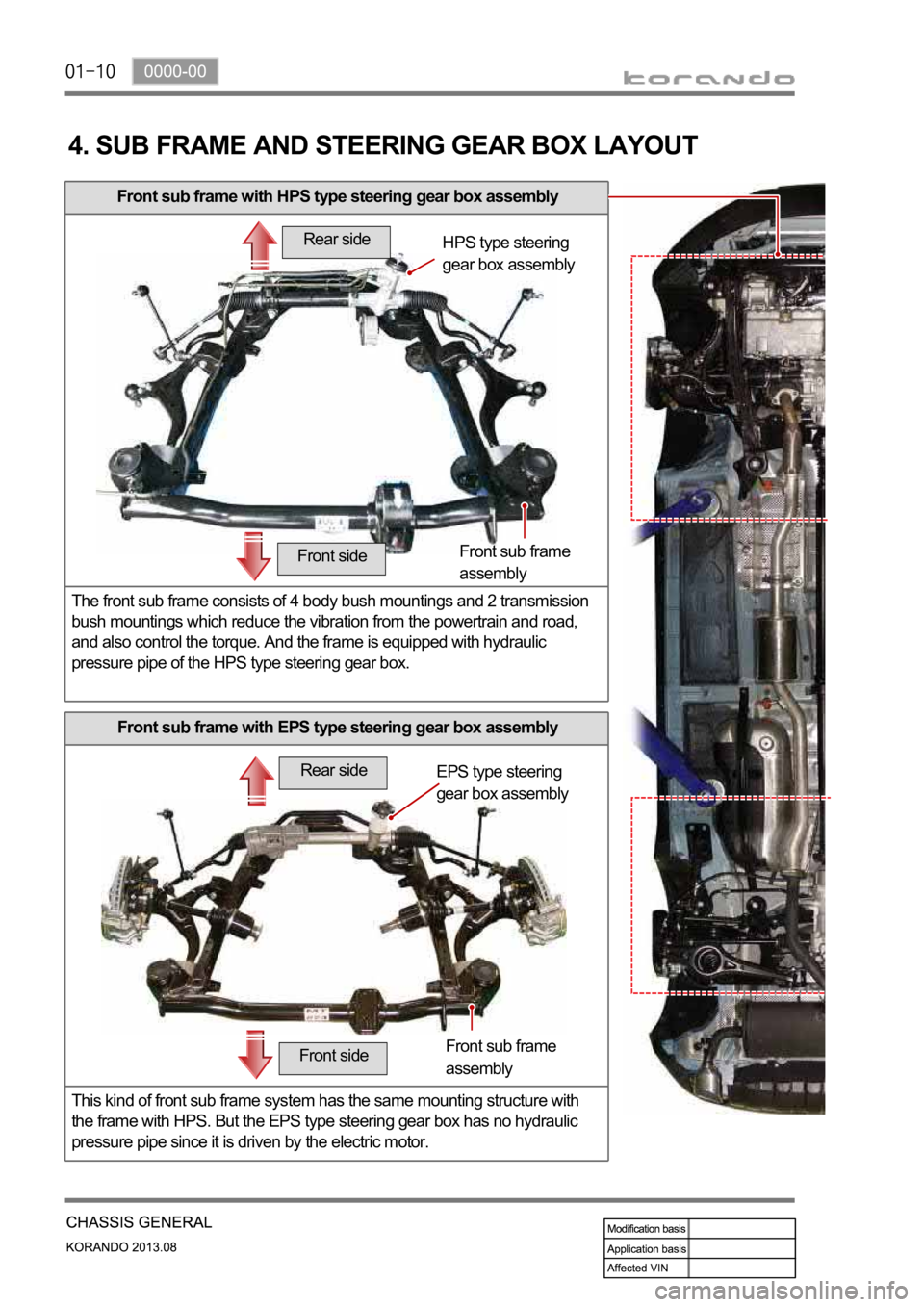
Front sub frame with HPS type steering gear box assembly
The front sub frame consists of 4 body bush mountings and 2 transmission
bush mountings which reduce the vibration from the powertrain and road,
and also control the torque. And the frame is equipped with hydraulic
pressure pipe of the HPS type steering gear box.
4. SUB FRAME AND STEERING GEAR BOX LAYOUT
Front sub frame with EPS type steering gear box assembly
This kind of front sub frame system has the same mounting structure with
the frame with HPS. But the EPS type steering gear box has no hydraulic
pressure pipe since it is driven by the electric motor.
Rear side
Front sideHPS type steering
gear box assembly
Front sub frame
assembly
Rear side
Front side
EPS type steering
gear box assembly
Front sub frame
assembly