tire pressure SSANGYONG KORANDO 2013 User Guide
[x] Cancel search | Manufacturer: SSANGYONG, Model Year: 2013, Model line: KORANDO, Model: SSANGYONG KORANDO 2013Pages: 1336, PDF Size: 92.18 MB
Page 858 of 1336
8510-00
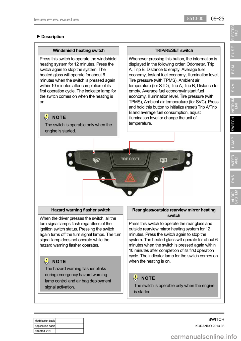
Windshield heating switch
Press this switch to operate the windshield
heating system for 12 minutes. Press the
switch again to stop the system. The
heated glass will operate for about 6
minutes when the switch is pressed again
within 10 minutes after completion of its
first operation cycle. The indicator lamp for
the switch comes on when the heating is
on.
Hazard warning flasher switch
When the driver presses the switch, all the
turn signal lamps flash regardless of the
ignition switch status. Pressing the switch
again turns off the turn signal lamps. The turn
signal lamp does not operate while the
hazard warning flasher operates.
TRIP/RESET switch
Whenever pressing this button, the information is
displayed in the following order: Odometer, Trip
A, Trip B, Distance to empty, Average fuel
economy, Instant fuel economy, Illumination level,
Tire pressure (with TPMS), Ambient air
temperature (for STD); Trip A, Trip B, Distance to
empty, Average fuel economy/Instant fuel
economy, Illumination level, Tire pressure (with
TPMS), Ambient air temperature (for SVC). Press
and hold this button to initialize (reset) Trip A/Trip
B and average fuel consumption, adjust
illumination level or change the unit of
temperature.
Description
Rear glass/outside rearview mirror heating
switch
Press this switch to operate the rear glass and
outside rearview mirror heating system for 12
minutes. Press the switch again to stop the
system. The heated glass will operate for about 6
minutes when the switch is pressed again within
10 minutes after completion of its first operation
cycle. The indicator lamp for the switch comes on
when the heating is on.
The switch is operable only when the engine
is started.
The hazard warning flasher blinks
during emergency hazard warning
lamp control and air bag deployment
signal activation.
The switch is operable only when the
engine is started.
Page 982 of 1336
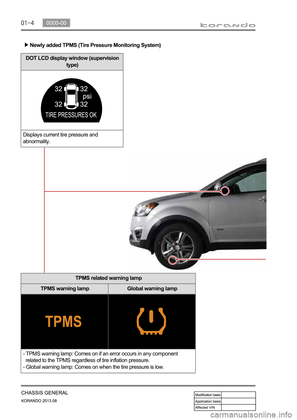
Newly added TPMS (Tire Pressure Monitoring System)
TPMS related warning lamp
TPMS warning lamp Global warning lamp
- TPMS warning lamp: Comes on if an error occurs in any component
related to the TPMS regardless of tire inflation pressure.
- Global warning lamp: Comes on when the tire pressure is low.
DOT LCD display window (supervision
type)
Displays current tire pressure and
abnormality.
Page 983 of 1336

0000-00
Wheel module
The wheel modules are mounted to each wheel rim and hole. They transmit
the signal of the pressure and temperature in tire, rotating direction and
wheel module ID code, etc. using the radio frequency to the TPMS ECU.
TPMS ECU
The TPMS ECU is located to the rear bumper rail under the vehicle. It outputs the tire pressure
information and CAN data.
Page 985 of 1336
0000-00
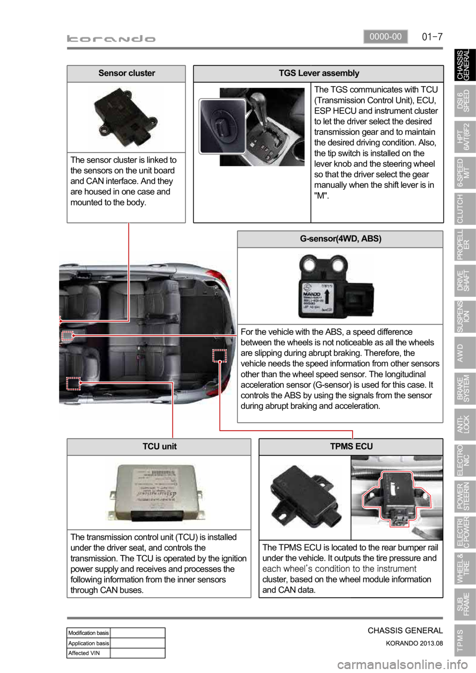
TPMS ECU
The TPMS ECU is located to the rear bumper rail
under the vehicle. It outputs the tire pressure and
cluster, based on the wheel module information
and CAN data.
G-sensor(4WD, ABS)
For the vehicle with the ABS, a speed difference
between the wheels is not noticeable as all the wheels
are slipping during abrupt braking. Therefore, the
vehicle needs the speed information from other sensors
other than the wheel speed sensor. The longitudinal
acceleration sensor (G-sensor) is used for this case. It
controls the ABS by using the signals from the sensor
during abrupt braking and acceleration.
TCU unit
The transmission control unit (TCU) is installed
under the driver seat, and controls the
transmission. The TCU is operated by the ignition
power supply and receives and processes the
following information from the inner sensors
through CAN buses.
TGS Lever assembly
The TGS communicates with TCU
(Transmission Control Unit), ECU,
ESP HECU and instrument cluster
to let the driver select the desired
transmission gear and to maintain
the desired driving condition. Also,
the tip switch is installed on the
lever knob and the steering wheel
so that the driver select the gear
manually when the shift lever is in
"M".Sensor cluster
The sensor cluster is linked to
the sensors on the unit board
and CAN interface. And they
are housed in one case and
mounted to the body.
Page 1000 of 1336
4) Basic Inspection
(1) Horn operation
Listen for the horn sound when pressing the horn pad on the steering wheel. -
(2) Brake operation
Check if there is any abnormal noise, unusually long braking distance, or uneven braking force. If the
brake warning lamp does not go out even after starting the engien or are flashing during driving,
have the brake system checked immediately.
Check the brake pipes and hoses for connection, oil leak, crack or interference after changing the
position of tires. When replacing the tires, check the brake disc for surface condition and wear.
Check the parking brake cable and brake operation. Shorten the checking interval if the parking
brake is used frequently. -
-
-
(3) Exhaust system
Be aware to any changes in sound or smell from the exhaust system. These may be caused by leak or
overheat. Have the exhaust system checked and repaired immediately.
Inspect the exhaust system including catalytic converter. Inspect all the components and body frame
near the exhaust system. -
-
(4) Tires
Unusual vibration of the steering wheel and seats or pulling to one side on the straight and level roads
may indicates the uneven tire inflation pressure or poor wheel balance. -
(5) Steering and suspension system
Inspect the front and rear suspension and the steering system for damage, looseness or missing
parts, signs of wear or lack of lubrication. Inspect the power steering line and the hoses for
connection, leak, crack and chafing. Inspect the drive axle boot and seals for damage, tear or leak.
Replace or repair the system if necessary. -
(6) Engine oil
Check the oil level when the engine is still warm and add the specified engine oil if necessary. -
(7) Coolant
Check the coolant level in the coolant reservoir, coolant conditions (contamination, foreign material),
and hoses for damage and leak. Replace or add the Ssangyong genuine coolant, if needed. -
(8) Engine drive belt
Check all drive belts on the engine for wear, crack and looseness. Retighten or replace the belt, if
needed. -
Page 1111 of 1336
4890-00
KAMM circle
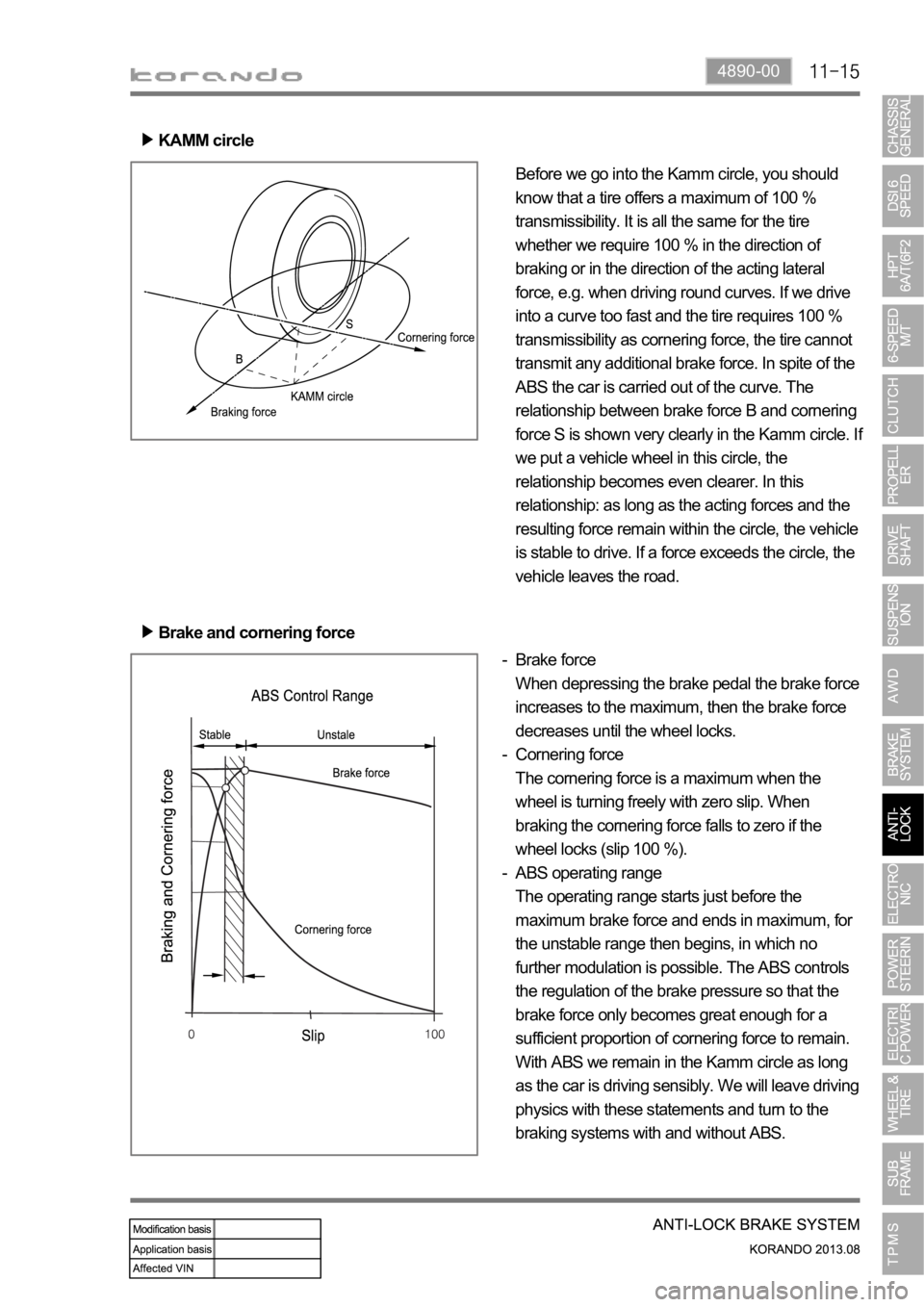
Before we go into the Kamm circle, you should
know that a tire offers a maximum of 100 %
transmissibility. It is all the same for the tire
whether we require 100 % in the direction of
braking or in the direction of the acting lateral
force, e.g. when driving round curves. If we drive
into a curve too fast and the tire requires 100 %
transmissibility as cornering force, the tire cannot
transmit any additional brake force. In spite of the
ABS the car is carried out of the curve. The
relationship between brake force B and cornering
force S is shown very clearly in the Kamm circle. I
f
we put a vehicle wheel in this circle, the
relationship becomes even clearer. In this
relationship: as long as the acting forces and the
resulting force remain within the circle, the vehicle
is stable to drive. If a force exceeds the circle, the
vehicle leaves the road.
Brake force
When depressing the brake pedal the brake force
increases to the maximum, then the brake force
decreases until the wheel locks.
Cornering force
The cornering force is a maximum when the
wheel is turning freely with zero slip. When
braking the cornering force falls to zero if the
wheel locks (slip 100 %).
ABS operating range
The operating range starts just before the
maximum brake force and ends in maximum, for
the unstable range then begins, in which no
further modulation is possible. The ABS controls
the regulation of the brake pressure so that the
brake force only becomes great enough for a
sufficient proportion of cornering force to remain.
With ABS we remain in the Kamm circle as long
as the car is driving sensibly. We will leave driving
physics with these statements and turn to the
braking systems with and without ABS. -
-
- Brake and cornering force
Page 1155 of 1336
4170-00
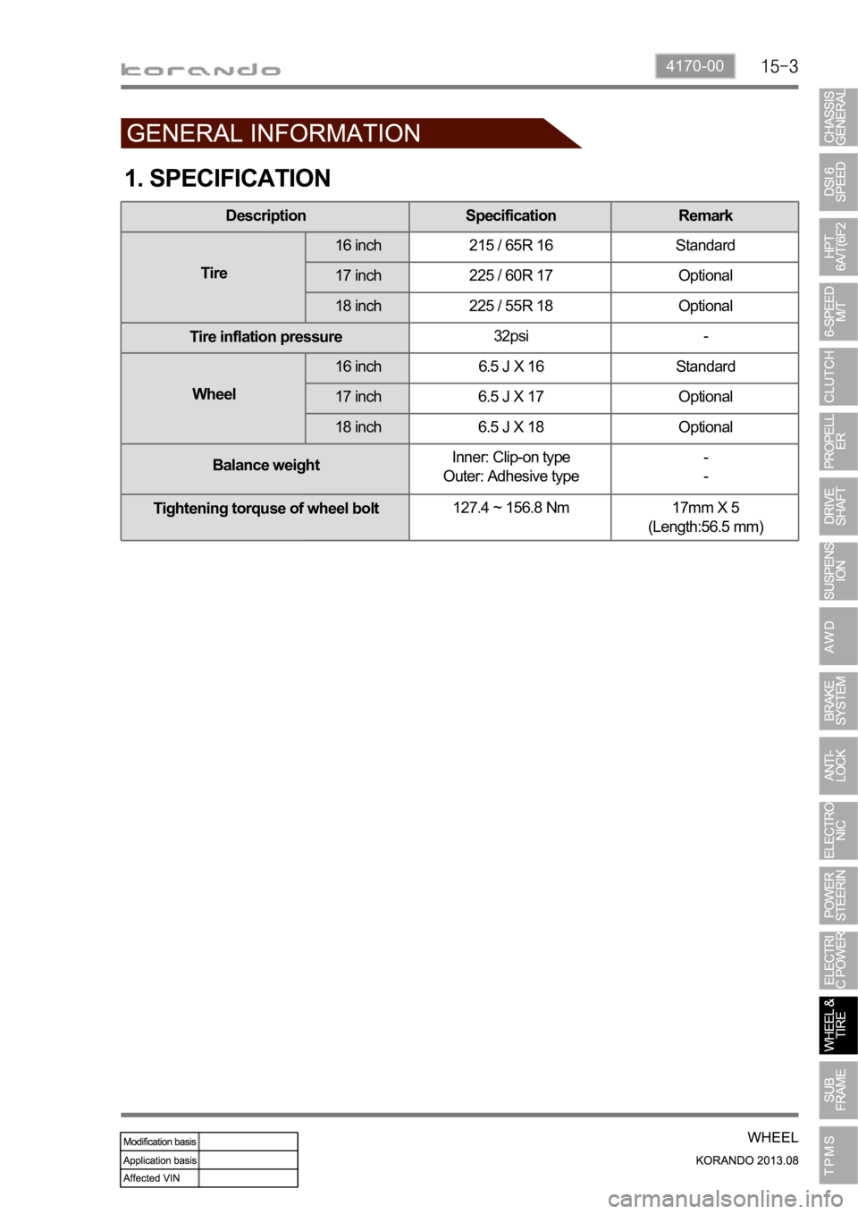
1. SPECIFICATION
Description Specification Remark
Tire16 inch 215 / 65R 16 Standard
17 inch 225 / 60R 17 Optional
18 inch 225 / 55R 18 Optional
Tire inflation pressure32psi -
Wheel16 inch 6.5 J X 16 Standard
17 inch 6.5 J X 17 Optional
18 inch 6.5 J X 18 Optional
Balance weightInner: Clip-on type
Outer: Adhesive type-
-
Tightening torquse of wheel bolt127.4 ~ 156.8 Nm 17mm X 5
(Length:56.5 mm)
Page 1157 of 1336

4170-00
Wheel module
The wheel modules are mounted to each wheel rim and hole. They transmit the signal of the pressure
and temperature in tire, rotating direction and wheel module ID code, etc. using the radio frequency to
the TPMS ECU.
Repair kit
Repair kit changed
Newly added TPMS (Tire Pressure Monitoring System)
Page 1158 of 1336
1. OVERVIEW
A radial tire uses a cord angle of 90 degrees. That is, the cord material runs in a radial or direct line from
one bead to the other across the tread. In addition, a radial tire has a belt overwrap under the tread
surface to provide greater structural stability. The belt overwrap of a radial tire distortion while the radial
structure enables high speed driving.
Tire supports the weight of the vehicle, reduces the impact from the road and at the same time,
transmits the power to propel, brake and steer on the road. It also functions to maintain a
vessel of air.
There is wear limit mark on the tire, which protrudes as a strip shape located approximately 1.6 mm from
mark on the shoulder to let the driver find the wear mark easily. To measure the tire groove depth,
measure at any point other than the point which has a wear limit mark.
The tire is worn unevenly according to the driver's driving habit, improper servicing, low tire inflation
pressure, changed tire location, etc.
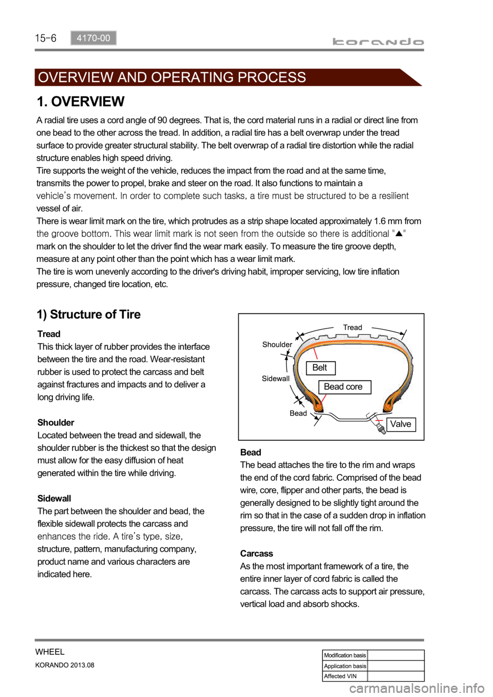
1) Structure of Tire
Tread
This thick layer of rubber provides the interface
between the tire and the road. Wear-resistant
rubber is used to protect the carcass and belt
against fractures and impacts and to deliver a
long driving life.
Shoulder
Located between the tread and sidewall, the
shoulder rubber is the thickest so that the design
must allow for the easy diffusion of heat
generated within the tire while driving.
Sidewall
The part between the shoulder and bead, the
flexible sidewall protects the carcass and
structure, pattern, manufacturing company,
product name and various characters are
indicated here. Bead
The bead attaches the tire to the rim and wraps
the end of the cord fabric. Comprised of the bead
wire, core, flipper and other parts, the bead is
generally designed to be slightly tight around the
rim so that in the case of a sudden drop in inflation
pressure, the tire will not fall off the rim.
Carcass
As the most important framework of a tire, the
entire inner layer of cord fabric is called the
carcass. The carcass acts to support air pressure,
vertical load and absorb shocks.
Valve
Belt
Bead core
Page 1159 of 1336
4170-00
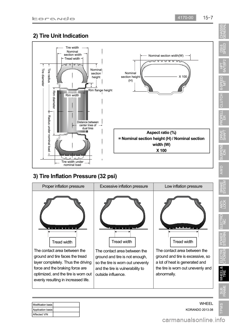
2) Tire Unit Indication
Aspect ratio (%)
= Nominal section height (H) / Nominal section
width (W)
X 100
3) Tire Inflation Pressure (32 psi)
Proper inflation pressure Excessive inflation pressure Low inflation pressure
The contact area between the
ground and tire faces the tread
layer completely. Thus the driving
force and the braking force are
optimized, and the tire is worn out
evenly resulting in increased life.The contact area between the
ground and tire is not enough,
so the tire is worn out unevenly
and the tire is vulnerability to
outside influence.The contact area between the
ground and tire is excessive, so
a lot of heat is generated and
the tire is worn out unevenly and
abnormally.
Tread widthTread widthTread width