SSANGYONG KORANDO 2013 Service Manual
KORANDO 2013
SSANGYONG
SSANGYONG
https://www.carmanualsonline.info/img/67/57503/w960_57503-0.png
SSANGYONG KORANDO 2013 Service Manual
Page 598 of 1336
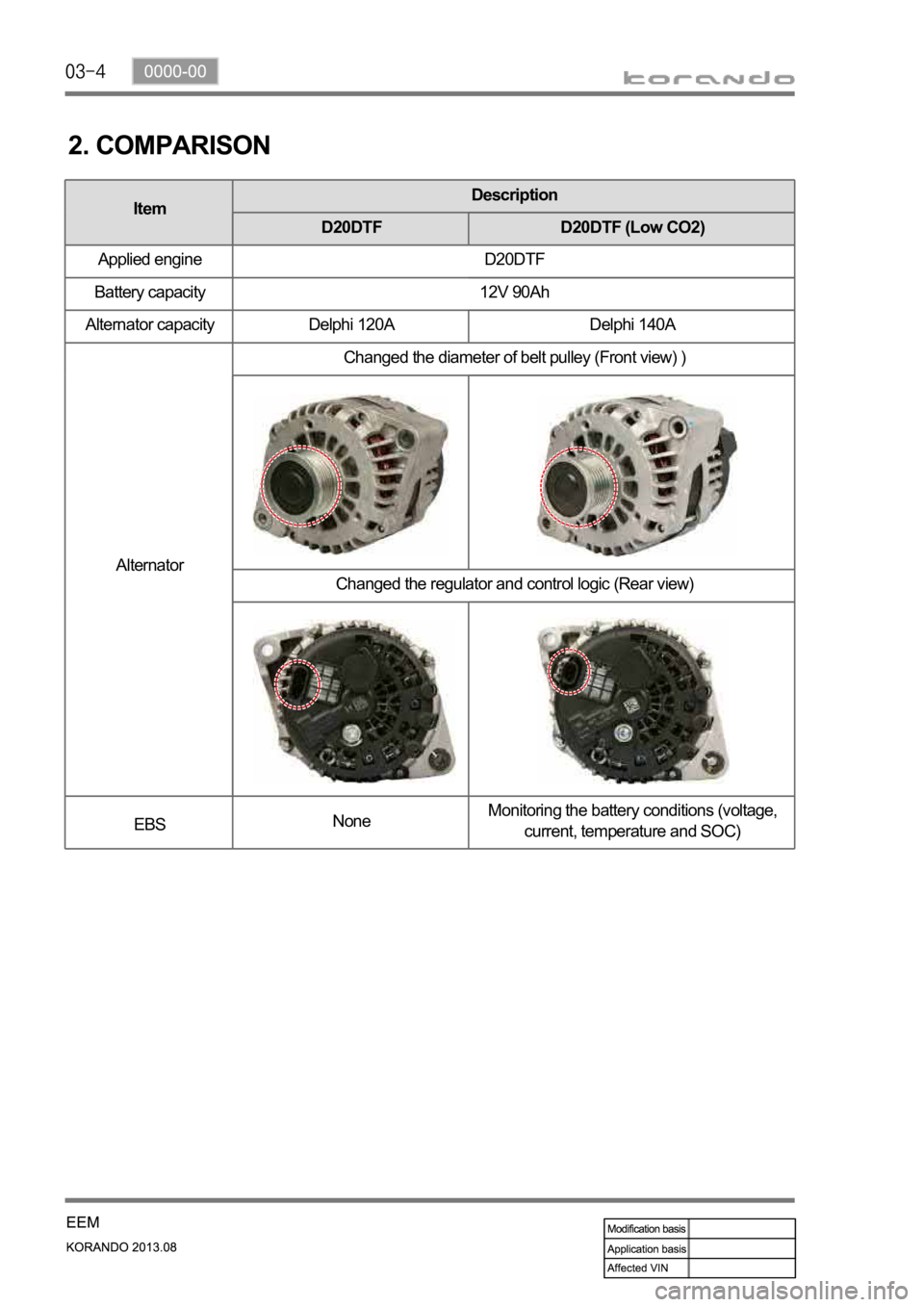
ItemDescription
D20DTF D20DTF (Low CO2)
Applied engine D20DTF
Battery capacity 12V 90Ah
Alternator capacity Delphi 120A Delphi 140A
AlternatorChanged the diameter of belt pulley (Front view) )
Changed the regulator and control logic (Rear view)
EBSNoneMonitoring the battery conditions (voltage,
current, temperature and SOC)
2. COMPARISON
Page 600 of 1336
Measuring at (-) wiring
Measure the voltage between battery wiring
and body ground. -
Specified valuebelow 0.3V
If the voltage is out of the specified value,
check the wiring mounting bolt for corrosion
and looseness. If there is a poor contact due
to corrosion or paint, wipe out the contact area
and retighten it.
Wiring mounting bolt to body
ground (-): 17 Nm
Measuring the battery voltage
Stop the engine and wait for 20 minutes.
Measure the voltage between terminal (+)
and terminal (-) with the ignition switch OFF
and all electric devices OFF. -
Specified valueover 12V
Page 601 of 1336
0000-00
Measuring the voltage drop between lines
Measure the voltage drop between alternator B+ and battery B+. -
Specified valuebelow 0.3V
If the value is out of the specified value, check the terminal and clamp for looseness.
Checking the charge warning lamp
Check if the charge warning lamp goes out.
If the charge warning lamp does not go off, inspect the electric circuit.
Start the engine and check if the charge warning lamp keeps off. 1.
2.
-
3.
Page 603 of 1336
0000-00
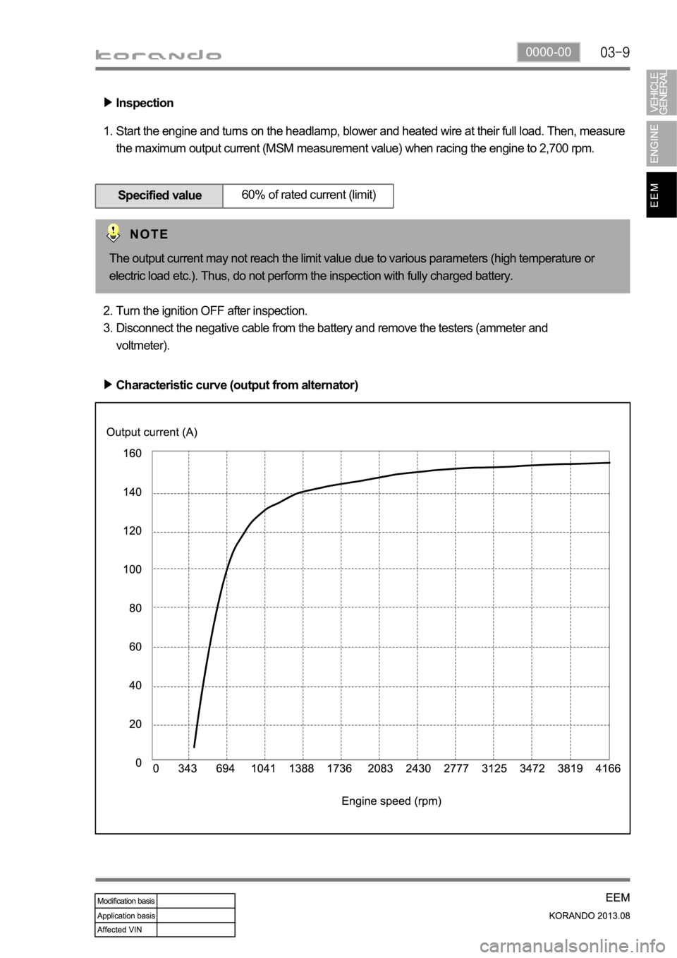
Inspection
Start the engine and turns on the headlamp, blower and heated wire at their full load. Then, measure
the maximum output current (MSM measurement value) when racing the engine to 2,700 rpm. 1.
Specified value60% of rated current (limit)
Turn the ignition OFF after inspection.
Disconnect the negative cable from the battery and remove the testers (ammeter and
voltmeter). 2.
3.
Characteristic curve (output from alternator)
The output current may not reach the limit value due to various parameters (high temperature or
electric load etc.). Thus, do not perform the inspection with fully charged battery.
Page 604 of 1336
5. INSPECTION - REGULATING VOLTAGE
Perform the basic inspection. -
Setting up the testers
Preparation
Set up the ammeter and voltmeter as shown
in the figure. 1.
Inspection
Turn the ignition ON and measure the voltage on the voltmeter. 1.
Start the engine and turn all electric devices OFF.
Increase the engine speed to 2,700 rpm and maintain the speed. Measure the voltage when the
output current from alternator decrease below 30A. 2.
3.
Specified valueover 12V
Specified value11.5 ~ 15.5V
Make sure to set up the tester while keeping
its polarity.
Page 609 of 1336
0000-00
8. DTC SETTING CONDITIONS
Charge warning lamp ON condition
Turn the ignition ON (Engine stopped)
Open or short circuit of L terminal wiring, open or short internal circuit of alternator (fixed control of
13.8V)
Open or short circuit of F terminal wiring, no feedback output signal 1.
2.
3.
Page 611 of 1336
0000-00
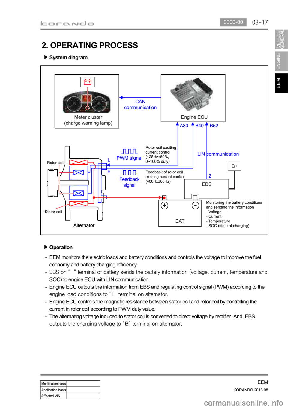
2. OPERATING PROCESS
System diagram
Operation
EEM monitors the electric loads and battery conditions and controls the voltage to improve the fuel
economy and battery charging efficiency.
SOC) to engine ECU with LIN communication.
Engine ECU outputs the information from EBS and regulating control signal (PWM) according to the
Engine ECU controls the magnetic resistance between stator coil and rotor coil by controlling the
current in rotor coil according to PWM duty value.
The alternating voltage induced to stator coil is converted to direct voltage by rectifier. And, EBS
-
-
-
-
-
Page 612 of 1336
Operation of charge warning lamp
ECU checks the generating voltage from alternator and circuit conditions and sends the warning lamp ON
signal to meter cluster through CAN line.Basic control logic according to the driving conditions
Engine ECU determines the engine loads according to the fuel injection volume and engine speed. It
charges the battery by increasing the generating voltage during deceleration. To improve the fuel
economy by reducing the alternator load during acceleration, engine ECU decreases the generating
voltage and consumes the battery voltage.
Page 631 of 1336
8410-00
2. CHECKING CABLES AND WIRES
Check for loose connection or rust.
Check terminals and wires for corrosion due to electrolyte leakage.
Check terminals and wires for open circuit.
Check the wire insulation and coat for damage, cracks or deterioration.
Check if the conductive parts of the terminals do not contact with vehicle body or other metal parts.
Check that the grounding part has continuity with mounting bolts and vehicle body.
Check that wires are properly routed.
Make sure that wires are securely fixed to avoid contact with sharp body parts and high-temperature
parts, such as the exhaust manifold and exhaust pipes.
The rotating parts, such as fan pulley and fan belt, perturbative parts and wiring should be secured
tightly at regular intervals.
Secure the wiring between the fixed parts, such as the vehicle body, and vibrating parts, such as the
engine, after slackening it slightly to prevent it from being damaged. -
-
-
-
-
-
-
-
-
-
Page 632 of 1336
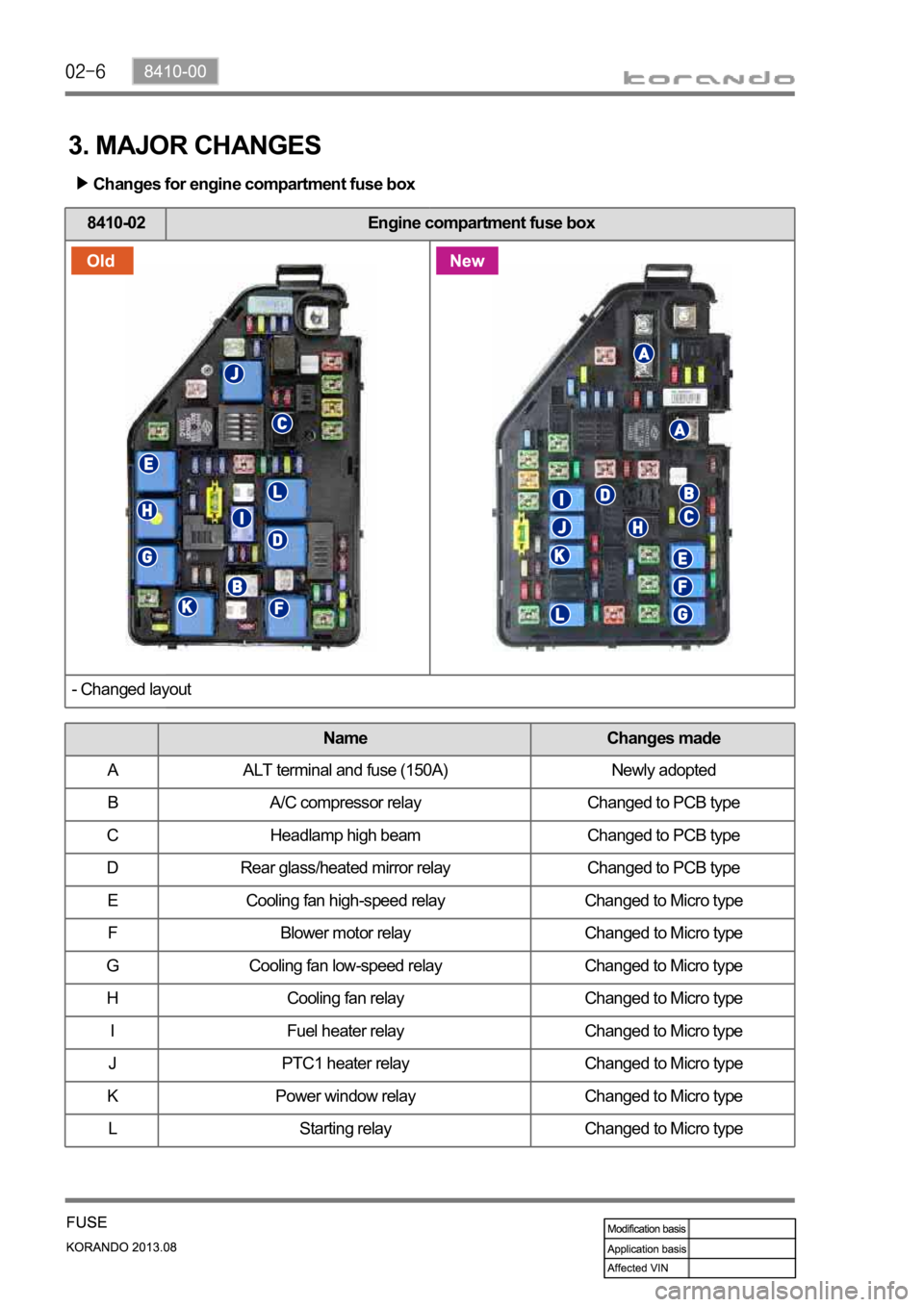
3. MAJOR CHANGES
Changes for engine compartment fuse box
8410-02 Engine compartment fuse box
- Changed layout
Name Changes made
A ALT terminal and fuse (150A) Newly adopted
B A/C compressor relay Changed to PCB type
C Headlamp high beam Changed to PCB type
D Rear glass/heated mirror relay Changed to PCB type
E Cooling fan high-speed relay Changed to Micro type
F Blower motor relay Changed to Micro type
G Cooling fan low-speed relay Changed to Micro type
H Cooling fan relay Changed to Micro type
I Fuel heater relay Changed to Micro type
J PTC1 heater relay Changed to Micro type
K Power window relay Changed to Micro type
L Starting relay Changed to Micro type
