engine SSANGYONG KORANDO 2013 Service Manual
[x] Cancel search | Manufacturer: SSANGYONG, Model Year: 2013, Model line: KORANDO, Model: SSANGYONG KORANDO 2013Pages: 1336, PDF Size: 92.18 MB
Page 1132 of 1336
0000-00
5) ARP (Active Roll-Over Protection)
The ARP (Active Roll-over Protection) system is a safety assistant device that minimizes, by controlling
brakes and the engine, the physical tendency of the vehicle rollover during sharp lane changes or U-
turns. For the system, software is added to the existing ESP system and no additional device or switch is
needed. One must note that the ARP system, just as general assistant devices including the ABS, is only
a safety assistant device using the ESP system and its function is useless when the situation overcomes
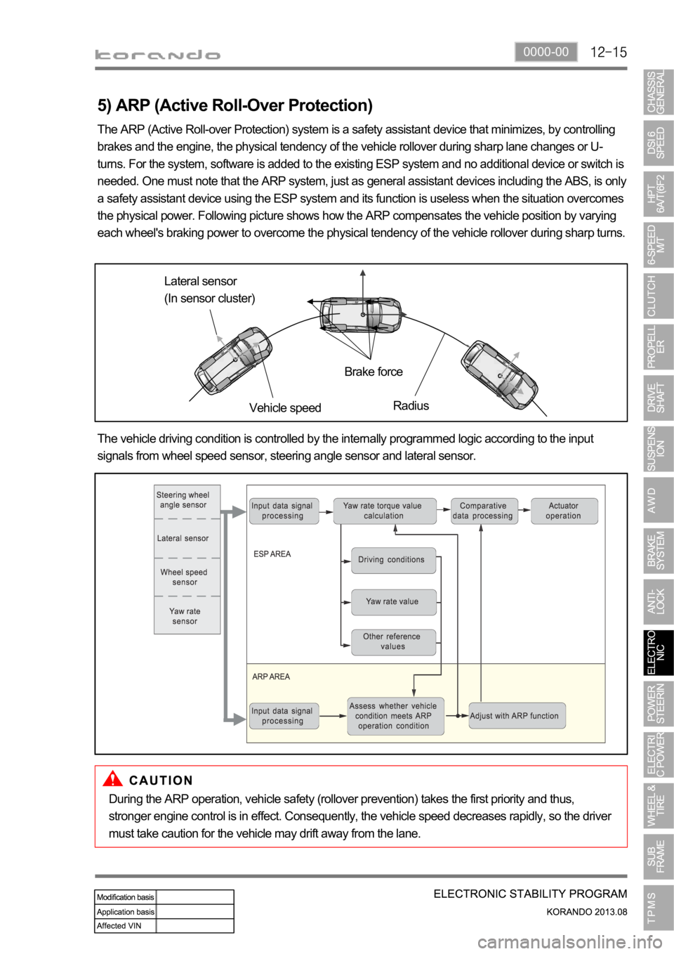
the physical power. Following picture shows how the ARP compensates the vehicle position by varying
each wheel's braking power to overcome the physical tendency of the vehicle rollover during sharp turns.
Lateral sensor
(In sensor cluster)
Vehicle speedBrake force
Radius
The vehicle driving condition is controlled by the internally programmed logic according to the input
signals from wheel speed sensor, steering angle sensor and lateral sensor.
During the ARP operation, vehicle safety (rollover prevention) takes the first priority and thus,
stronger engine control is in effect. Consequently, the vehicle speed decreases rapidly, so the driver
must take caution for the vehicle may drift away from the lane.
Page 1137 of 1336
Circuit description
When compared to the vehicle equipped with ABS/EBD only, the internal hydraulic circuit has a
normally-open separation valve and a shuttle valve in primary circuit and in secondary circuit.
When the vehicle brakes are not applied during engine running or when applying the non-ABS operating
brakes, the normally-open separation valve and the inlet valve are open, whereas the normally-closed
shuttle valve and the outlet valve are closed.
When the ESP system is operating, the normally-open separation valve will be closed by the solenoid
valve operation and the hydraulic circuit will be established by the shuttle valve. Then, the inlet and outlet
valves will be closed or open depending on the braking pressure RISE, HOLD or DUMP conditions.
Flashing warning lamp and warning sound during ESP operation
When the ESP operates while the vehicle is moving, the ESP warning lamp on the instrument panel
flickers and the buzzer sounds at every 0.1 second. The ESP lamp operation is to inform a driver that the
vehicle is extremely unstable.
The ESP system is just a supplementary system for the vehicle and it cannot control the vehicle over the
physical limit. Do not solely rely on the system but be advised to drive the vehicle safely.
Drive feeling during ESP operation
When the ESP system activates, the driving feeling can be different depending on vehicle driving
conditions. For example, it will feel different when the ESP system is activated while the ABS is operated
by depressing the brake pedal and when the ESP system is in control without the brake pedal
depressed on the same curve.
If the ESP system operates with the brake applied, the brake pressure will be increased on the
corresponding wheel which already has braking pressure for the ESP controls. In other words, the ESP
system would make the driver feel more abruptly braked compared to the situation that the braking
pressure is applied to wheel which had no braking force.
Noise and vibration that driver senses during ESP operation
The ESP system may transfer noise and vibration to a driver due to the pressure changes caused by the
motor and valve operations in a very short period of time.
Extreme cornering will trigger the ESP operation and this will make the driver sense noise and vibration
due to sudden brake application.
Also, the ESP system controls the engine power. Therefore, the driver may notice the engine power
decreases even when the accelerator pedal is depressed.
Page 1149 of 1336
0000-00
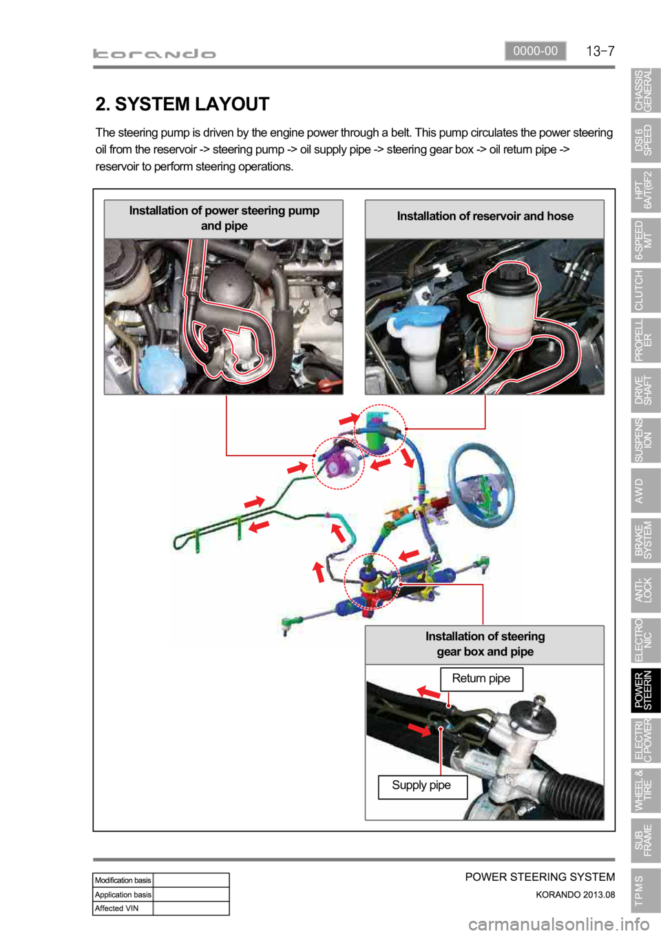
Installation of steering
gear box and pipe
Installation of reservoir and hoseInstallation of power steering pump
and pipe
2. SYSTEM LAYOUT
The steering pump is driven by the engine power through a belt. This pump circulates the power steering
oil from the reservoir -> steering pump -> oil supply pipe -> steering gear box -> oil return pipe ->
reservoir to perform steering operations.
Return pipe
Supply pipe
Page 1153 of 1336
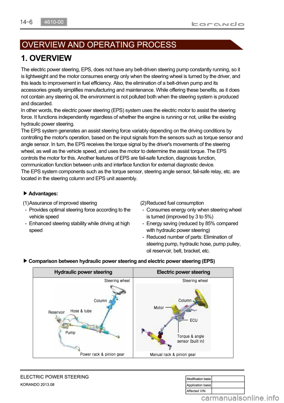
Hydraulic power steering Electric power steering
1. OVERVIEW
The electric power steering, EPS, does not have any belt-driven steering pump constantly running, so it
is lightweight and the motor consumes energy only when the steering wheel is turned by the driver, and
this leads to improvement in fuel efficiency. Also, the elimination of a belt-driven pump and its
accessories greatly simplifies manufacturing and maintenance. While offering these benefits, as it does
not contain any steering oil, the environment is not polluted both when the steering system is produced
and discarded.
In other words, the electric power steering (EPS) system uses the electric motor to assist the steering
force. It functions independently regardless of whether the engine is running or not, unlike the existing
hydraulic power steering.
The EPS system generates an assist steering force variably depending on the driving conditions by
controlling the motor's operation, based on the input signals from the sensors such as torque sensor and
angle sensor. In turn, the EPS receives the torque signal by the driver's movements of the steering
wheel, as well as the vehicle speed, and uses the motor to determine the assist torque. The EPS
controls the motor for this. Another features of EPS are fail-safe function, diagnosis function,
communication function between units and interface function for external diagnostic device.
The EPS system components such as the torque sensor, steering angle sensor, fail-safe relay, etc. are
located in the steering column and EPS unit assembly.
Advantages:
Assurance of improved steering
Provides optimal steering force according to the
vehicle speed
Enhanced steering stability while driving at high
speed (1)
-
-Reduced fuel consumption
Consumes energy only when steering wheel
is turned (improved by 3 to 5%)
Energy saving (reduced by 85% compared
with hydraulic power steering)
Reduced number of parts: Elimination of
steering pump, hydraulic hose, pump pulley,
oil reservoir, belt, bracket, etc. (2)
-
-
-
Comparison between hydraulic power steering and electric power steering (EPS)
Page 1168 of 1336
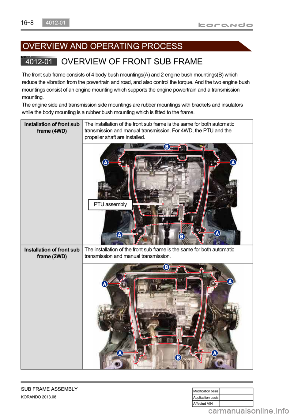
The front sub frame consists of 4 body bush mountings(A) and 2 engine bush mountings(B) which
reduce the vibration from the powertrain and road, and also control the torque. And the two engine bush
mountings consist of an engine mounting which supports the engine powertrain and a transmission
mounting.
The engine side and transmission side mountings are rubber mountings with brackets and insulators
while the body mounting is a rubber bush mounting which is fitted to the frame.
Installation of front sub
frame (4WD)The installation of the front sub frame is the same for both automatic
transmission and manual transmission. For 4WD, the PTU and the
propeller shaft are installed.
Installation of front sub
frame (2WD)The installation of the front sub frame is the same for both automatic
transmission and manual transmission.
PTU assembly
Page 1181 of 1336
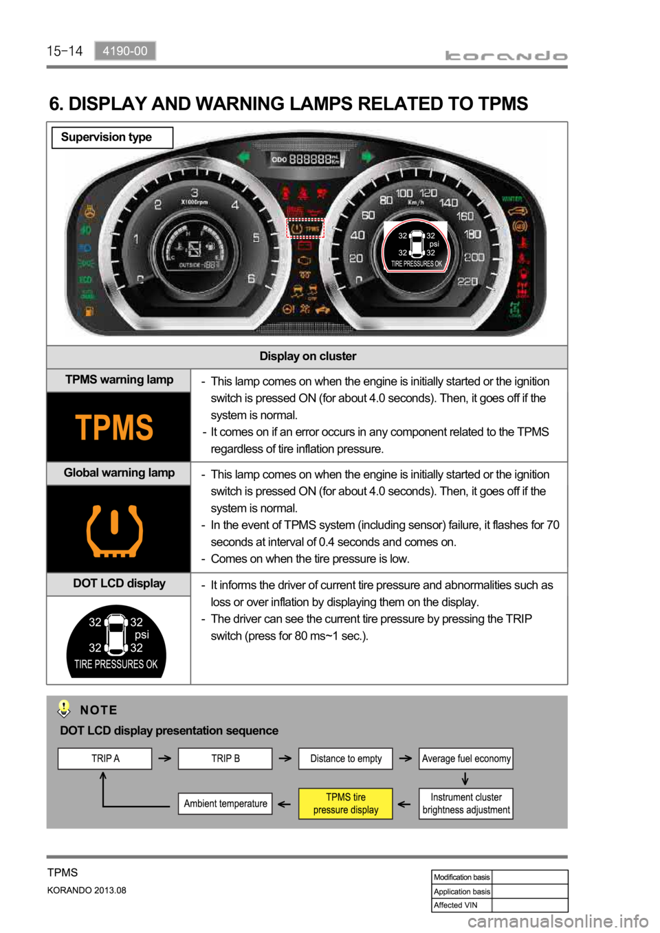
Display on cluster
TPMS warning lamp
Global warning lamp
DOT LCD display
6. DISPLAY AND WARNING LAMPS RELATED TO TPMS
This lamp comes on when the engine is initially started or the ignition
switch is pressed ON (for about 4.0 seconds). Then, it goes off if the
system is normal.
It comes on if an error occurs in any component related to the TPMS
regardless of tire inflation pressure. -
-
This lamp comes on when the engine is initially started or the ignition
switch is pressed ON (for about 4.0 seconds). Then, it goes off if the
system is normal.
In the event of TPMS system (including sensor) failure, it flashes for 70
seconds at interval of 0.4 seconds and comes on.
Comes on when the tire pressure is low. -
-
-
It informs the driver of current tire pressure and abnormalities such as
loss or over inflation by displaying them on the display.
The driver can see the current tire pressure by pressing the TRIP
switch (press for 80 ms~1 sec.). -
-
DOT LCD display presentation sequence
Supervision type
Page 1182 of 1336

4190-00
Display on cluster
TPMS warning lamp
Global warning lamp
DOT display
This lamp comes on when the engine is initially started or the ignition
switch is pressed ON (for about 4.0 seconds). Then, it goes off if the
system is normal.
It comes on if an error occurs in any component related to the TPMS
regardless of tire inflation pressure. -
-
This lamp comes on when the engine is initially started or the ignition
switch is pressed ON (for about 4.0 seconds). Then, it goes off if the
system is normal.
In the event of TPMS system (including sensor) failure, it flashes for 70
seconds at interval of 0.4 seconds and comes on.
Comes on when the tire pressure is low. -
-
-
The tire pressure for front wheels is displayed on the LCD display. The
tire pressure for rear wheels is displayed when pressing the Trip switch. -
Standard type
DOT display presentation sequence
Page 1194 of 1336

2. LAYOUT
1) Exterior Layout
Liquid and suction pipe
The high/low-pressure A/C refrigerant flows
through this pipe. It is fitted with the refrigerant
pressure sensor.
Electric fan
It cools down the A/C condenser to speed up the
compression for the refrigerant in the condenser.
Refrigerant pressure sensor
It is mounted to the latter part of the right
headlamp. It converts the A/C refrigerant pressure
to voltage value and sends it to the engine ECU.
A/C compressor
It is installed to the left side of the engine
assembly, compresses the low-temperature and
low-pressure coolant and converts it to the high-
temperature and high-pressure coolant. Then, it
sends the coolant to the A/C condenser.
Page 1195 of 1336

6810-00
A/C condenser & receiver drier
It is installed in front of vehicle and condenses vapor
refrigerant into low temperature and high pressure liquid
refrigerant. The receiver drier is built in it.Ambient temperature sensor
It is mounted to the front section of the
vehicle and detects the ambient
temperature to send the voltage value
according to the resistance change to
the heater and A/C control assembly.
Engine ECU
It controls the A/C compressor, electric fan
and PTC heater according to the signal from
the A/C control panel.
Expansion valve
It is mounted to the inlet of the evaporator
core and supplies the appropriate quantity
of refrigerant to the evaporator.
Integrated receiver drier
Page 1197 of 1336

6810-00
Intake sensor
It is mounted to the side of
evaporator core and detects the
temperature of the evaporator
core.Water temperature
sensor
It is mounted to the heater pipe
part and detects the coolant
temperature.
3) Air Conditioner Module Layout
Temp actuator
It changes the air mix door
opening according to the
control command from the
heater and A/C control
assembly.Evaporator core
It cools the surrounding air by
passing through the low-
temperature and low-pressure
refrigerant sprayed from the
expansion valve.
Heater core
It is mounted to the left-hand of
the air conditioner module and
heats the indoor using the heat
of the engine coolant.
Mode actuator
It controls the air outlet damper
to the five directions according
to the control command from
the heater and A/C control
assembly.