engine SSANGYONG KORANDO 2013 Service Manual
[x] Cancel search | Manufacturer: SSANGYONG, Model Year: 2013, Model line: KORANDO, Model: SSANGYONG KORANDO 2013Pages: 1336, PDF Size: 92.18 MB
Page 1202 of 1336

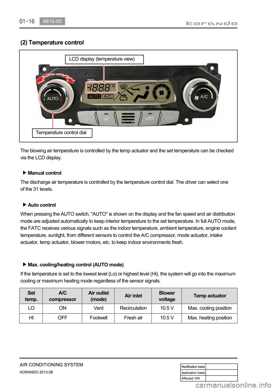
(2) Temperature control
The blowing air temperature is controlled by the temp actuator and the set temperature can be checked
via the LCD display.
Manual control
The discharge air temperature is controlled by the temperature control dial. The driver can select one
of the 31 levels.
Auto control
When pressing the AUTO switch, "AUTO" is shown on the display and the fan speed and air distribution
mode are adjusted automatically to keep interior temperature to the set temperature. In full AUTO mode,
the FATC receives various signals such as the indoor temperature, ambient temperature, engine coolant
temperature, sunlight, from different sensors to control the A/C compressor, mode actuator, intake
actuator, temp actuator, blower motors, etc. to keep indoor environments fresh.
Max. cooling/heating control (AUTO mode)
If the temperature is set to the lowest level (Lo) or highest level (Hi), the system will go into the maximum
cooling or maximum heating mode regardless of the sensor signals.
Set
temp.A/C
compressorAir outlet
(mode)Air inletBlower
voltageTemp actuator
LO ON Vent Recirculation 10.5 V Max. cooling position
HI OFF Footwell Fresh air 10.5 V Max. heating position
Temperature control dial
LCD display (temperature view)
Page 1204 of 1336

Initial fan speed control for cooling/heating
Cooling start control
by the air flow from the vent. Therefore, at the initial operation stage, the hot air is discharged to the
windshield (DEF mode) for about 5 seconds. -
Heating start control
When the engine coolant temperature is low or the wind temperature is not warmed up sufficiently,
the driver might feel uncomfortable by the air flow from the vent. Therefore, the fan speed is set to the
1st stage and the cool air is sent to the windshield until the coolant temperature increases to the
proper level (DEF mode). As the engine coolant temperature goes up, the mode is changed to
Defrost & Foot mode or AUTO mode to increase the speed of blower motor. This control is cancelled
control time must not exceed 10 minutes. -
Page 1209 of 1336

6810-00
(6) A/C control
The air conditioner is controlled by the A/C compressor of the engine ECU according to the signal from
the heater and A/C control assembly. The driver can see the air conditioner operation through the LCD
display and the indicator of the A/C switch.
Manual control
Pressing the A/C switch or selecting defrost mode turns on the A/C.
Auto control
The A/C is controlled in accordance with the indoor temperature and ambient temperature.
or below) in winter, the compressor is turned off to protect the A/C compressor.
A/C switch
LCD display (A/C operation view)
Page 1220 of 1336

(6) A/C control
The air conditioner is operated at the defroster mode and MAX air conditioner mode and when the A/C
switch is turned to "ON" position. It is controlled by the A/C compressor of the engine ECU according to
the signal from the heater and A/C control assembly. The driver can see that the A/C has been activated
when an indicator lamps at the A/C switch and MAX A/C switch comes on. If the intake sensor detects
the freezing of the evaporator core, it stops the air conditioner by turning off the compressor.
MAX A/C control
This is designed for increasing driver comfort. When the switch is pressed, the air conditioner is
operated and vent and recirculation modes are selected automatically. The discharge temperature and
fan speed are regulated depending on the driver's choice.
A/C switch
MAX A/C control switch
Page 1221 of 1336

6810-00
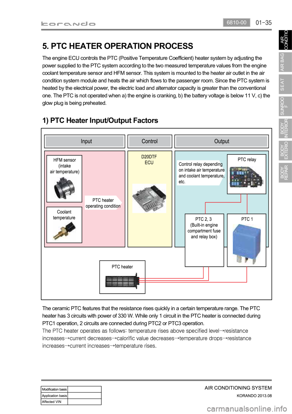
5. PTC HEATER OPERATION PROCESS
1) PTC Heater Input/Output Factors
The engine ECU controls the PTC (Positive Temperature Coefficient) heater system by adjusting the
power supplied to the PTC system according to the two measured temperature values from the engine
coolant temperature sensor and HFM sensor. This system is mounted to the heater air outlet in the air
condition system module and heats the air which flows to the passenger room. Since the PTC system is
heated by the electrical power, the electric load and alternator capacity is greater than the conventional
one. The PTC is not operated when a) the engine is cranking, b) the battery voltage is below 11 V, c) the
glow plug is being preheated.
The ceramic PTC features that the resistance rises quickly in a certain temperature range. The PTC
heater has 3 circuits with power of 330 W. While only 1 circuit in the PTC heater is connected during
PTC1 operation, 2 circuits are connected during PTC2 or PTC3 operation.
Page 1222 of 1336

2) Control Condition For PTC Heater
Operation Operating condition PTC heater status
HI mode operation
(PTC2, 3)PTC heater operates in
"HIGH" mode if operating
conditions are met
LO mode operation
(PTC1)PTC heater operates in
"LOW" mode if operating
conditions are met
Conditions for
deactivating
Air conditioner blower switch OFF
When the ambient temperature sensor is
faulty (short or open circuit in the wiring)
Engine is cranking
Battery voltage is 11 V or less
Glow plug is being preheated (Glow indicator
comes on) -
-
-
-
-
-
-
-
-
Conditions for PTC heater "LOW" operation mode (2nd step)
Page 1230 of 1336

8810-00
A large quantity of non-toxic gas (nitrogen gas) is generated with a loud noise when the air bag or
seat belt pretensioner deploys. If these airborne particles irritate your skin, eyes, nose, or throat, rinse
the area with cool water. If the irritation continues, see your doctor.
The windshield glass may be broken when the passenger air bag deploys.
The air bag is a unit to save an occupant's life from a sudden accident and it inflates at a very fast
speed by gas with high temperature, which might cause injury, such as an abrasion, bruise and burn
depending on the accident conditions.
The air bag components will be very hot after deployment. Do not touch them.
The deployed air bag/seat belt pretensioner cannot deploy again. It will work when an additional
impact is applied. Once the air bag system is triggered, the triggered air bag assembly should be
removed from the vehicle and replaced with a new one.
The air bag warning lamp is illuminated for 3 to 7 seconds after the engine is started to check
the system. If this warning lamp remains ON, then the system may be defective. Have the air
bag system checked immediately by Ssangyong Dealer or Ssangyong Authorized Service
Operation.
Incorrect inspection can result in serious injuries or malfunctions in the air bag and seat belt
pretensioner system. 12.
13.
14.
15.
16.
17.
18.
Page 1232 of 1336

8810-00
1. AIR BAG SYSTEM OVERVIEW
The air bag system is divided into front air bag system and side air bag system. The system protects the
occupant's body by deploying the air bags in the event of a collision. The system consists of 8 inflators
including the inflators of the seat belt pretensioners, air bag unit (SDM), and 4 impact sensors on the
front side and both sides of the vehicle. The air bag unit (SDM) determines the operation of each air bag
module and seat belt pretensioners using the crash signals from the front and side impact sensors in the
event of a collision. The front and side air bag systems are operated independently, and the body control
module (BCM) activates the auto door unlock function and various lamps including hazard warning lamp
and room lamps, when the crash signal from the SDM is received to notify others of emergency situation
and let the occupant escape easily. The SDM is equipped with self diagnosis function, and it performs
the diagnosis on the internal/external devices of the air bag system for a certain period of time after IGN
ON. And it monitors the air bag system regularly and turns on the air bag warning lamp on the
instrument cluster when a fault is found in the system, to notify the driver. The SDM has event data
recorder (EDR) function that stores the driving information data transmitted through CAN communication
from various units (vehicle speeds, engine rpm, brake application, etc.) in a crash or near crash event,
when the acceleration sensor in the air bag unit detects a sharp acceleration change, regardless of the
air bag deployment
Page 1258 of 1336

7410-00
2. WARNINGS FOR POWER SEAT
Adjust the driver seat before driving.
Make sure that the seat is firmly secured after adjusting.
Never drive the vehicle with the head restraint removed or lowered excessively. Otherwise, you
r
neck, spine or other parts of the body can be severely injured in the event of an accident.
If you recline the seatback excessively, you could slide under the seat belt and be injured severely
in a collision.
Do not put any object that could damage the seat on the seat.
The front and rear seats are equipped with the heated wire (seat warmer) system. Using the seat
warmer system excessively may cause minor burns. The following occupants should exercise
special care when using the heated wire seat.
Infants, children, old or handicapped persons
Persons with sensitive skin
Exhausted persons
Persons who is drunk or took medicine which causes drowsiness such as sleeping pills, cold
tablets, etc. -
-
-
-
Do not place anything on the seat that insulates against the heat, such as a blanket or cushion.
Make sure that the head restraints are in place and secured properly. Never drive the vehicle with
the head restraint removed.
To minimize the injuries in a collision or an abrupt stop, make sure the seatback is in the upright
position before driving. If the seatback is reclined too much, the occupant could slide under the seat
belt in a collision or an abrupt stop and cannot be protected properly by the air bag system.
3. CAUTIONS FOR POWER SEAT
You can operate the power seat with the ignition switch OFF. However, frequent operation of the
seat switch with the engine stopped can result in battery becoming discharged.
Operating more than one seat adjustment switch at the same time can cause damage to the seat
motor. Therefore, operate the seat switch only one at a time.
Do not use organic solvents such as benzene, thinner, alcohol or gasoline to prevent the seat cove
r
from being damaged while cleaning.
Do not operate the seat position adjustment switch forcefully when the seat does not move or it
contacts an object.
If the power seat is not operated, check and correct the problem before driving off.
Page 1274 of 1336

7410-00
(2) Front seat heated wire and ventilation unit diagram
Condition: Engine running
seat heated wire and ventilation switch. Every time the switch is pressed, the temperature level goes
down by one level. Pressing the switch a third time will turn off the operation.
The front seat heated wire and ventilation functions cannot be operated at the same time.