fuel system SSANGYONG KORANDO 2013 Owner's Manual
[x] Cancel search | Manufacturer: SSANGYONG, Model Year: 2013, Model line: KORANDO, Model: SSANGYONG KORANDO 2013Pages: 1336, PDF Size: 92.18 MB
Page 252 of 1336
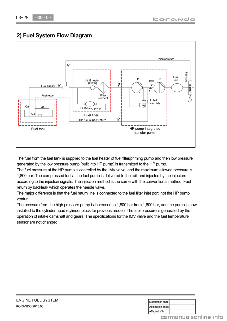
2) Fuel System Flow Diagram
The fuel from the fuel tank is supplied to the fuel heater of fuel filter/priming pump and then low pressure
generated by the low pressure pump (built into HP pump) is transmitted to the HP pump.
The fuel pressure at the HP pump is controlled by the IMV valve, and the maximum allowed pressure is
1,800 bar. The compressed fuel at the fuel pump is delivered to the rail, and injected by the injectors
according to the injection signals. The injection method is the same with the conventional method; Fuel
return by backleak which operates the needle valve.
The major difference is that the fuel return line is connected to the fuel filter inlet port, not the HP pump
venturi.
The pressure from the high pressure pump is increased to 1,800 bar from 1,600 bar, and the pump is now
installed to the cylinder head (cylinder block for previous model). The fuel pressure is generated by the
operation of intake camshaft and gears. The specifications for the IMV valve and the fuel temperature
sensor are not changed.
Page 255 of 1336
0000-00
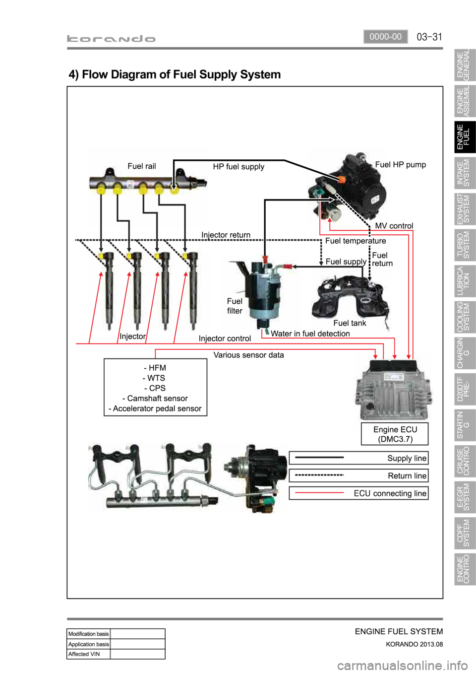
4) Flow Diagram of Fuel Supply System
Page 259 of 1336
0000-00
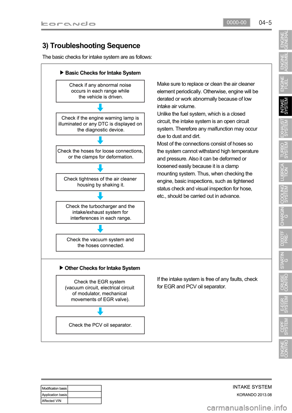
3) Troubleshooting Sequence
The basic checks for intake system are as follows:
Basic Checks for Intake System
Make sure to replace or clean the air cleaner
element periodically. Otherwise, engine will be
derated or work abnormally because of low
intake air volume.
Unlike the fuel system, which is a closed
circuit, the intake system is an open circuit
system. Therefore any malfunction may occur
due to dust and dirt.
Most of the connections consist of hoses so
the system cannot withstand high temperature
and pressure. Also it can be deformed or
loosened easily because it is a clamp
mounting system. Thus, when checking the
engine, basic inspections, such as tightened
status check and visual inspection for hose,
etc., should be carried out in advance.
Other Checks for Intake System
If the intake system is free of any faults, check
for EGR and PCV oil separator.
Page 265 of 1336
0000-00
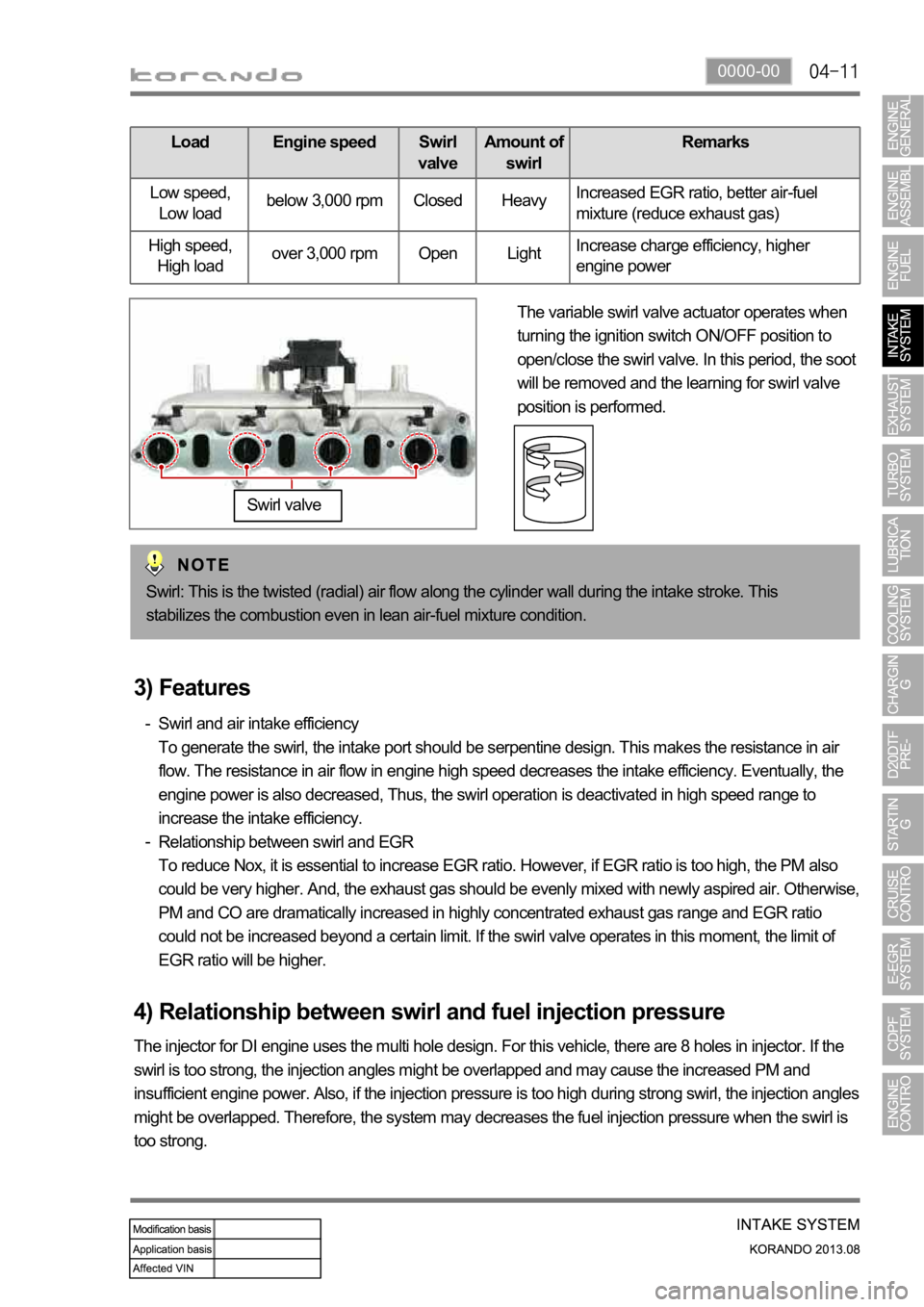
Load Engine speed Swirl
valveAmount of
swirlRemarks
Low speed,
Low loadbelow 3,000 rpm Closed HeavyIncreased EGR ratio, better air-fuel
mixture (reduce exhaust gas)
High speed,
High loadover 3,000 rpm Open LightIncrease charge efficiency, higher
engine power
The variable swirl valve actuator operates when
turning the ignition switch ON/OFF position to
open/close the swirl valve. In this period, the soot
will be removed and the learning for swirl valve
position is performed.
Swirl valve
Swirl: This is the twisted (radial) air flow along the cylinder wall during the intake stroke. This
stabilizes the combustion even in lean air-fuel mixture condition.
3) Features
Swirl and air intake efficiency
To generate the swirl, the intake port should be serpentine design. This makes the resistance in air
flow. The resistance in air flow in engine high speed decreases the intake efficiency. Eventually, the
engine power is also decreased, Thus, the swirl operation is deactivated in high speed range to
increase the intake efficiency.
Relationship between swirl and EGR
To reduce Nox, it is essential to increase EGR ratio. However, if EGR ratio is too high, the PM also
could be very higher. And, the exhaust gas should be evenly mixed with newly aspired air. Otherwise,
PM and CO are dramatically increased in highly concentrated exhaust gas range and EGR ratio
could not be increased beyond a certain limit. If the swirl valve operates in this moment, the limit of
EGR ratio will be higher. -
-
4) Relationship between swirl and fuel injection pressure
The injector for DI engine uses the multi hole design. For this vehicle, there are 8 holes in injector. If the
swirl is too strong, the injection angles might be overlapped and may cause the increased PM and
insufficient engine power. Also, if the injection pressure is too high during strong swirl, the injection angles
might be overlapped. Therefore, the system may decreases the fuel injection pressure when the swirl is
too strong.
Page 286 of 1336
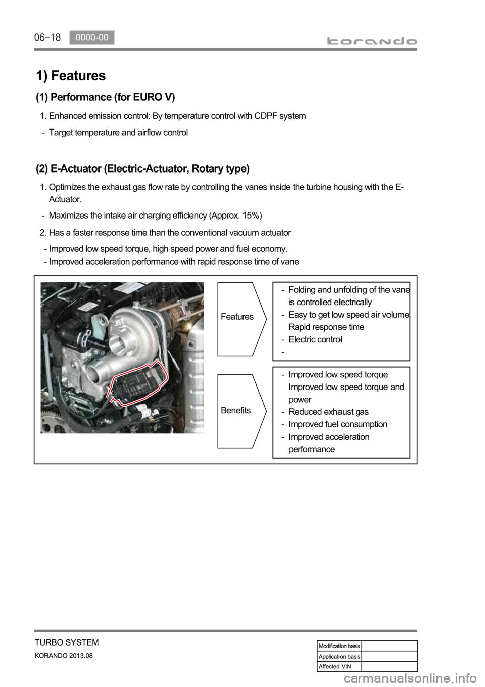
Maximizes the intake air charging efficiency (Approx. 15%) -Optimizes the exhaust gas flow rate by controlling the vanes inside the turbine housing with the E-
Actuator. 1.
(2) E-Actuator (Electric-Actuator, Rotary type)
Target temperature and airflow control -Enhanced emission control: By temperature control with CDPF system 1.
(1) Performance (for EURO V)
Has a faster response time than the conventional vacuum actuator 2.
Improved low speed torque, high speed power and fuel economy.
Improved acceleration performance with rapid response time of vane -
-
1) Features
Features
BenefitsFolding and unfolding of the vane
is controlled electrically
Easy to get low speed air volume
Rapid response time
Electric control -
-
-
-
Improved low speed torque
Improved low speed torque and
power
Reduced exhaust gas
Improved fuel consumption
Improved acceleration
performance -
-
-
-
Page 322 of 1336
1413-00
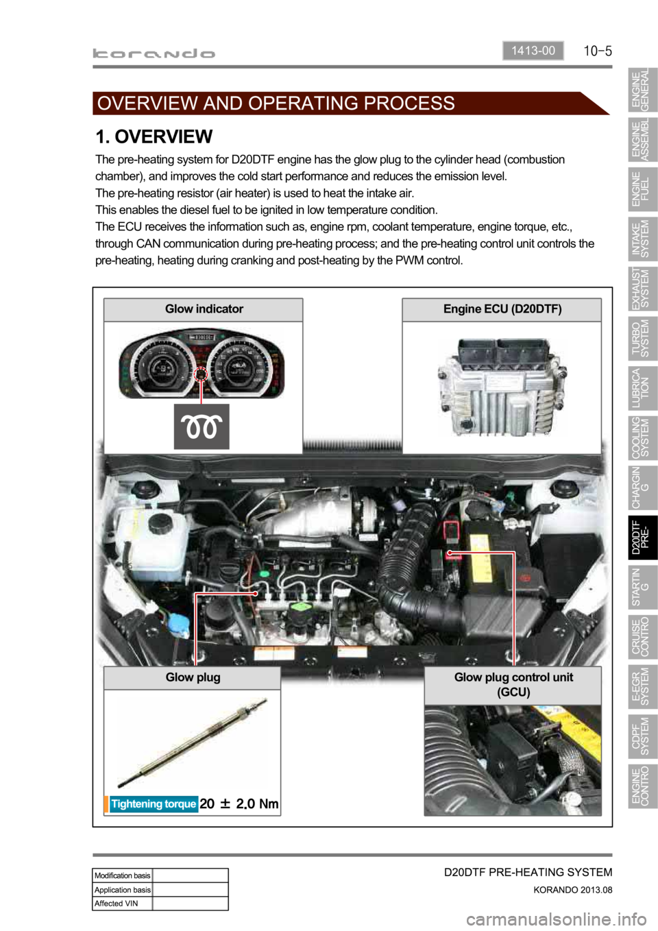
1. OVERVIEW
The pre-heating system for D20DTF engine has the glow plug to the cylinder head (combustion
chamber), and improves the cold start performance and reduces the emission level.
The pre-heating resistor (air heater) is used to heat the intake air.
This enables the diesel fuel to be ignited in low temperature condition.
The ECU receives the information such as, engine rpm, coolant temperature, engine torque, etc.,
through CAN communication during pre-heating process; and the pre-heating control unit controls the
pre-heating, heating during cranking and post-heating by the PWM control.
Glow plugGlow plug control unit
(GCU)
Glow indicatorEngine ECU (D20DTF)
Page 361 of 1336
1114-00
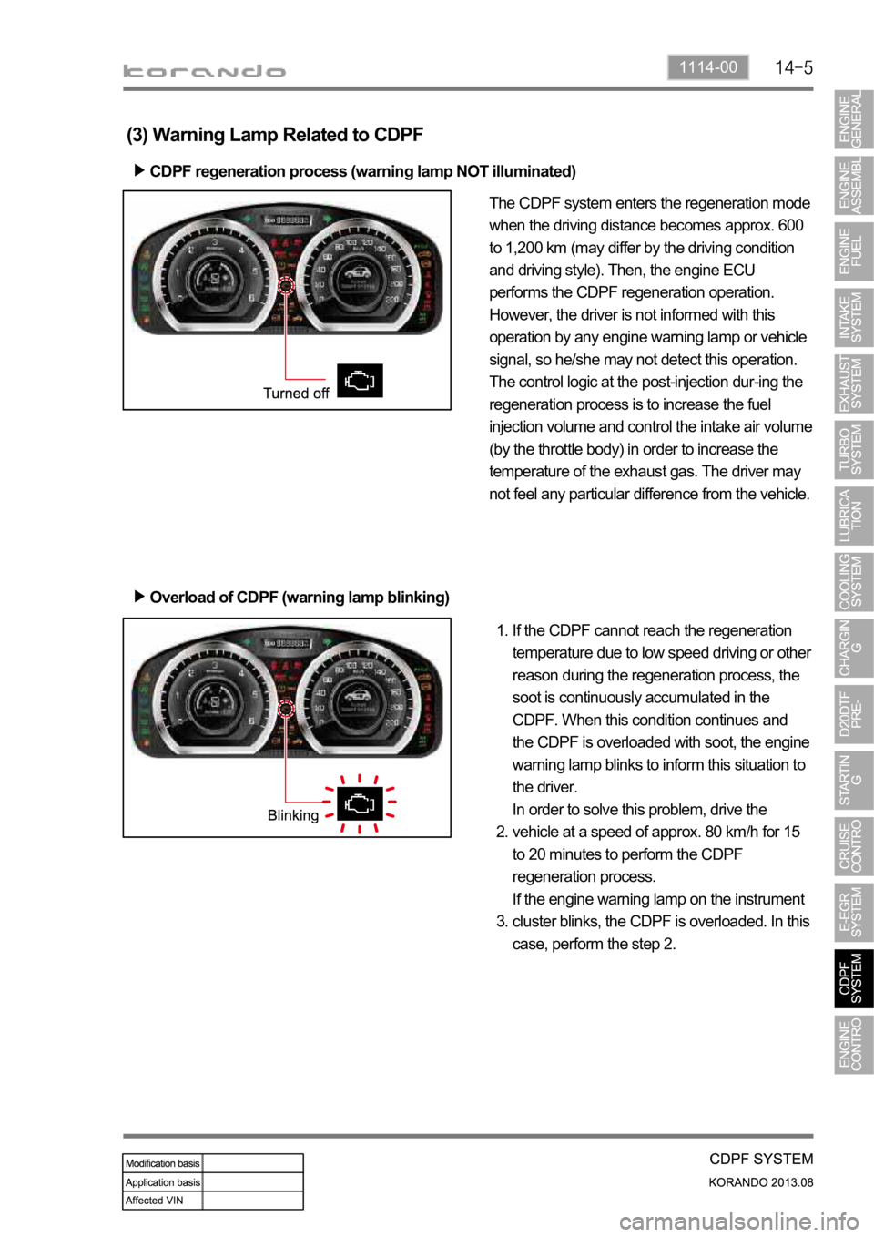
(3) Warning Lamp Related to CDPF
CDPF regeneration process (warning lamp NOT illuminated)
Overload of CDPF (warning lamp blinking)
The CDPF system enters the regeneration mode
when the driving distance becomes approx. 600
to 1,200 km (may differ by the driving condition
and driving style). Then, the engine ECU
performs the CDPF regeneration operation.
However, the driver is not informed with this
operation by any engine warning lamp or vehicle
signal, so he/she may not detect this operation.
The control logic at the post-injection dur-ing the
regeneration process is to increase the fuel
injection volume and control the intake air volume
(by the throttle body) in order to increase the
temperature of the exhaust gas. The driver may
not feel any particular difference from the vehicle.
If the CDPF cannot reach the regeneration
temperature due to low speed driving or other
reason during the regeneration process, the
soot is continuously accumulated in the
CDPF. When this condition continues and
the CDPF is overloaded with soot, the engine
warning lamp blinks to inform this situation to
the driver.
In order to solve this problem, drive the
vehicle at a speed of approx. 80 km/h for 15
to 20 minutes to perform the CDPF
regeneration process.
If the engine warning lamp on the instrument
cluster blinks, the CDPF is overloaded. In this
case, perform the step 2. 1.
2.
3.
Page 366 of 1336

A DPS (Differential Pressure Sensor) measures the pressure difference between before and after the
CDPF and detects whether the soot is collected in the CDPF or not. If PM is collected in the CDPF (In
this case the pressure difference between before and after the CDPF exceeds the specified value.
Normally, the system sends the signal when the driving distance becomes approx. 600 to 1,200 km), the
temperature of exhaust gas is increased and the post-injection is started for regeneration. The amount of
fuel post-injection is controlled by the exhaust gas temperature measured by the rear temperature
increase the regeneration temperature. Otherwise, the fuel injection amount is decreased or the fuel is
not injected.
When the engine is running with low load, the intake air amount is also controlled as well as fuel injection
amount. This function is used to increaser the combustion temperature by increasing the amount of fuel
post-injection with the lowest air amount within the specified control logic.
4. POST-INJECTION AND AIR MASS CONTROL
Page 380 of 1336
0000-00
2) ECU Control
(1) Function
a. ECU Function
ECU receives and analyzes signals from various sensors and then modifies those signals into
permissible voltage levels and analyzes to control respective actuators.
ECU microprocessor calculates injection period and injection timing proper for engine piston speed and
crankshaft angle based on input data and stored specific map to control the engine power and emission
gas.
Output signal of the ECU microprocessor drives pressure control valve to control the rail pressure and
activates injector solenoid valve to control the fuel injection period and injection timing; so controls
various actuators in response to engine changes. Auxiliary function of ECU has adopted to reduce
emission gas, improve fuel economy and enhance safety, comforts and conveniences. For example,
there are EGR, booster pressure control, autocruise (export only) and immobilizer and adopted CAN
communication to exchange data among electrical systems (automatic T/M and brake system) in the
vehicle fluently. And Scanner can be used to diagnose vehicle status and defectives.
water and electromagnetism and there should be no mechanical shocks.
To control the fuel volume precisely under repeated injections, high current should be applied instantly
so there is injector drive circuit in the ECU to generate necessary current during injector drive stages.
Current control circuit divides current applying time (injection time) into full-in-current-phase and hold-
current-phase and then the injectors should work very correctly under every working condition.
b. Control Function
Controls by operating stages
To make optimum combustion under every operating stage, ECU should calculate proper injection
volume in each stage by considering various factors.
Starting injection volume control
During initial starting, injecting fuel volume will be calculated by function of temperature and engine
cranking speed. Starting injection continues from when the ignition switch is turned to ignition
position to till the engine reaches to allowable minimum speed.
Driving mode control
If the vehicle runs normally, fuel injection volume will be calculated by accelerator pedal travel and
engine rpm and the drive map will be used to match the drivers inputs with optimum engine power. -
-
-
Page 383 of 1336
Pilot injection timing control
The pilot injection timing is determined as a function of the engine speed and of the total flow.
The elements are:
A first correction is made according to the air and coolant temperatures. This correction allows the
pilot injection timing to be adapted to the operating temperature of the engine.
A second correction is made according to the atmospheric pressure. This correction is used to adapt
the pilot injection timing as a function of the atmospheric pressure and therefore the altitude. -
-
d. Fuel Control
1. Main Flow Control
The main flow represents the amount of fuel injected into the cylinder during the main injection. The pilot
flow represents the amount of fuel injected during the pilot injection.
The total fuel injected during 1 cycle (main flow + pilot flow) is determined in the following manner.
When the driver depress the pedal, it is his demand which is taken into account by the system in order
to determine the fuel injected.
When the driver release the pedal, the idle speed controller takes over to determine the minimum fuel
which must be injected into the cylinder to prevent the enigne from stalling.
It is therefore the greater of these 2 values which is retained by the system. This value is then compared
with the lower flow limit determined by the ESP system.
As soon as the injected fuel becomes lower than the flow limit determined by the ESP system, the
antagonistic torque (engine brake) transmitted to the drive wheels exceeds the adherence capacity of
the vehicle and there is therefore a risk of the drive wheels locking.
The system thus chooses the greater of these 2 values (main flow & pilot flow) in order to prevent any
loss of control of the vehicle during a sharp deceleration.
As soon as the injected fuel becomes higher than the fuel limit determined by the ASR trajectory control
system, the engine torque transmitted to the wheels exceeds the adhesion capacity of the vehicle and
there is a risk of the drive wheels skidding. The system therefore chooses the smaller of the two values
in order to avoid any loss of control of the vehicle during accelerations.
The anti-oscillation strategy makes it possible to compensate for fluctuations in engine speed during
transient conditions. This strategy leads to a fuel correction which is added to the total fuel of each
cylinder.
The main fuel is obtained by subtracting the pilot injection fuel from the total fuel.
A mapping determines the minimum fuel which can control an injector as a function of the rail pressure.
As soon as the main fuel falls below this value, the fuel demand changes to 0 because in any case the
injector is not capable of injecting the quantity demand. A switch makes it possible to change over from the supercharge fuel to the total fuel according to the
state of the engine.
Until the stating phase has finished, the system uses the supercharged fuel.
Once the engine changes to normal operation, the system uses the total fuel. -
-