lock SSANGYONG KORANDO 2013 Service Manual
[x] Cancel search | Manufacturer: SSANGYONG, Model Year: 2013, Model line: KORANDO, Model: SSANGYONG KORANDO 2013Pages: 1336, PDF Size: 92.18 MB
Page 166 of 1336
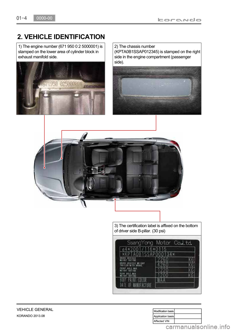
2) The chassis number
(KPTA0B1SSAP012345) is stamped on the righ
t
side in the engine compartment (passenger
side).
3) The certification label is affixed on the bottom
of driver side B-pillar. (30 psi)
2. VEHICLE IDENTIFICATION
1) The engine number (671 950 0 2 5000001) is
stamped on the lower area of cylinder block in
exhaust manifold side.
Page 188 of 1336
0000-00
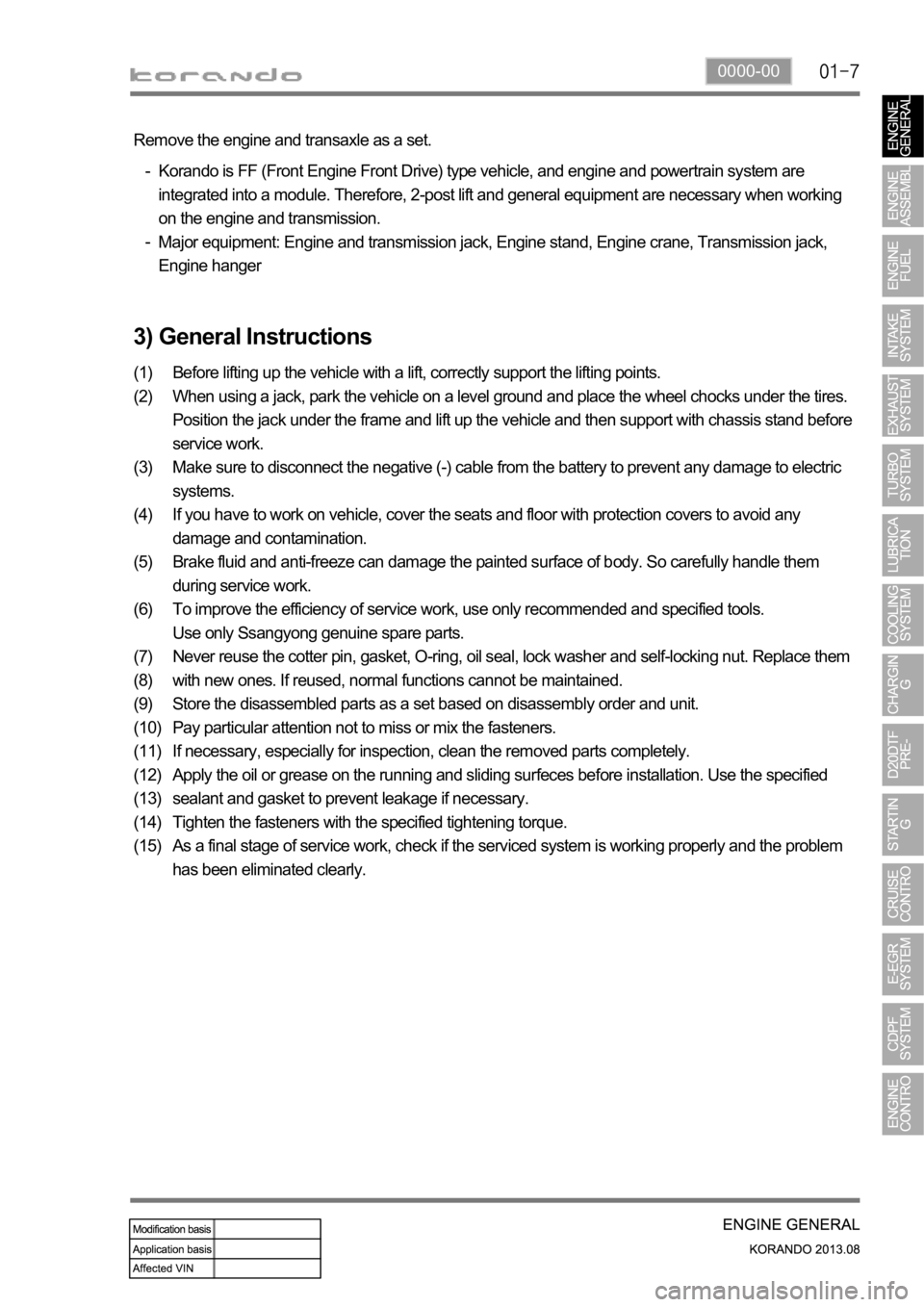
3) General Instructions
Before lifting up the vehicle with a lift, correctly support the lifting points.
When using a jack, park the vehicle on a level ground and place the wheel chocks under the tires.
Position the jack under the frame and lift up the vehicle and then support with chassis stand before
service work.
Make sure to disconnect the negative (-) cable from the battery to prevent any damage to electric
systems.
If you have to work on vehicle, cover the seats and floor with protection covers to avoid any
damage and contamination.
Brake fluid and anti-freeze can damage the painted surface of body. So carefully handle them
during service work.
To improve the efficiency of service work, use only recommended and specified tools.
Use only Ssangyong genuine spare parts.
Never reuse the cotter pin, gasket, O-ring, oil seal, lock washer and self-locking nut. Replace them
with new ones. If reused, normal functions cannot be maintained.
Store the disassembled parts as a set based on disassembly order and unit.
Pay particular attention not to miss or mix the fasteners.
If necessary, especially for inspection, clean the removed parts completely.
Apply the oil or grease on the running and sliding surfeces before installation. Use the specified
sealant and gasket to prevent leakage if necessary.
Tighten the fasteners with the specified tightening torque.
As a final stage of service work, check if the serviced system is working properly and the problem
has been eliminated clearly. (1)
(2)
(3)
(4)
(5)
(6)
(7)
(8)
(9)
(10)
(11)
(12)
(13)
(14)
(15) Remove the engine and transaxle as a set.
Korando is FF (Front Engine Front Drive) type vehicle, and engine and powertrain system are
integrated into a module. Therefore, 2-post lift and general equipment are necessary when working
on the engine and transmission.
Major equipment: Engine and transmission jack, Engine stand, Engine crane, Transmission jack,
Engine hanger -
-
Page 197 of 1336
0000-00
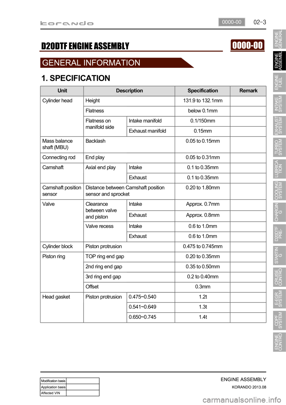
1. SPECIFICATION
Unit Description Specification Remark
Cylinder head Height 131.9 to 132.1mm
Flatness below 0.1mm
Flatness on
manifold sideIntake manifold 0.1/150mm
Exhaust manifold 0.15mm
Mass balance
shaft (MBU)Backlash 0.05 to 0.15mm
Connecting rod End play 0.05 to 0.31mm
Camshaft Axial end play Intake 0.1 to 0.35mm
Exhaust 0.1 to 0.35mm
Camshaft position
sensorDistance between Camshaft position
sensor and sprocket0.20 to 1.80mm
Valve Clearance
between valve
and pistonIntake Approx. 0.7mm
Exhaust Approx. 0.8mm
Valve recess Intake 0.6 to 1.0mm
Exhaust 0.6 to 1.0mm
Cylinder block Piston protrusion 0.475 to 0.745mm
Piston ring TOP ring end gap 0.20 to 0.35mm
2nd ring end gap 0.35 to 0.50mm
3rd ring end gap 0.2 to 0.40mm
Offset 0.3mm
Head gasket Piston protrusion 0.475~0.540 1.2t
0.541~0.649 1.3t
0.650~0.745 1.4t
Page 201 of 1336
0000-00
Knock sensor2-
Cam position sensor
1 10~14Nm -
T-MAP pressure sensor
1-
Exhaust manifold M8 10
-
Turbocharger M8 3
-
T/C support bracket bolt
1
-
T/C support bracket bolt
M8 1
-
T/C oil supply pipeM6(block side) 1
-
M6(turbo side) 1
-
T/C oil return pipe
(turbo side)2-
(block side)2-
EGR valve
3-
EGR pipe bolt
(Intake side)
2-
EGR pipe bolt
(EGR cooler side)
2-
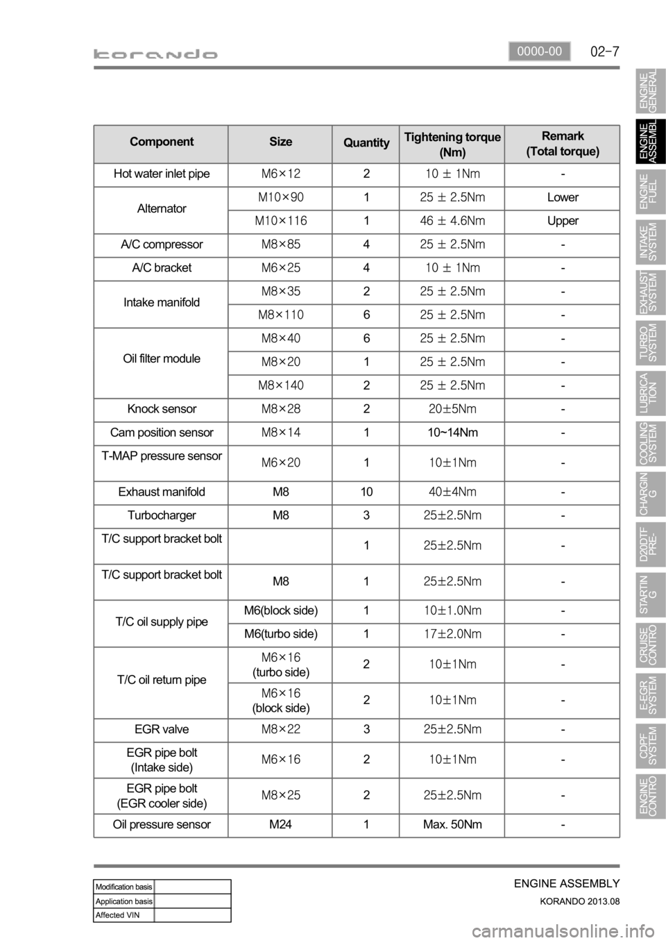
Oil pressure sensor M24 1 Max. 50Nm -
Component Size
QuantityTightening torque
(Nm)Remark
(Total torque)
Hot water inlet pipe
2-
Alternator
1Lower
1Upper
A/C compressor
4-
A/C bracket
4-
Intake manifold
2-
6-
Oil filter module
6-
1-
2-
Page 208 of 1336
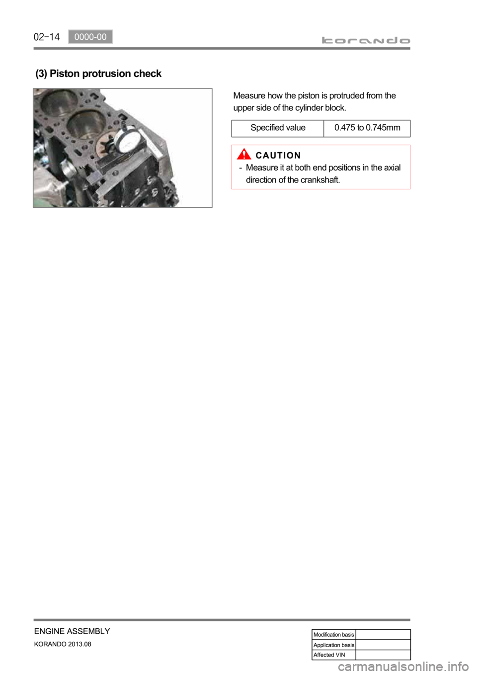
Measure how the piston is protruded from the
upper side of the cylinder block.
(3) Piston protrusion check
Specified value 0.475 to 0.745mm
Measure it at both end positions in the axial
direction of the crankshaft. -
Page 214 of 1336
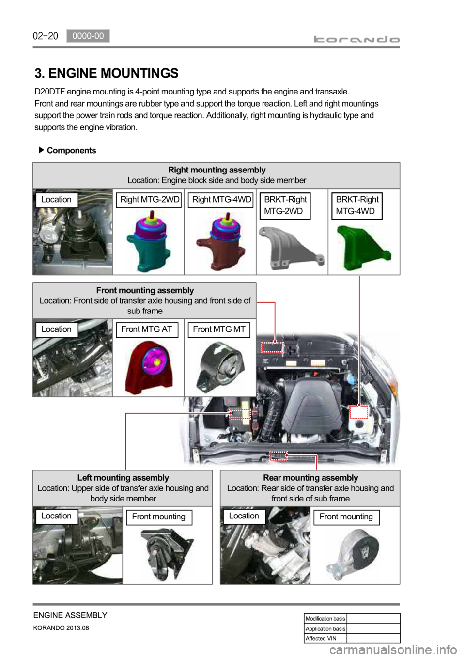
Front mounting assembly
Location: Front side of transfer axle housing and front side of
sub frame
Right mounting assembly
Location: Engine block side and body side member
Rear mounting assembly
Location: Rear side of transfer axle housing and
front side of sub frame
3. ENGINE MOUNTINGS
D20DTF engine mounting is 4-point mounting type and supports the engine and transaxle.
Front and rear mountings are rubber type and support the torque reaction. Left and right mountings
support the power train rods and torque reaction. Additionally, right mounting is hydraulic type and
supports the engine vibration.
Components
Left mounting assembly
Location: Upper side of transfer axle housing and
body side member
LocationFront mounting
Location
BRKT-Right
MTG-4WD
LocationFront mounting
BRKT-Right
MTG-2WD
Front MTG MTFront MTG AT
LocationRight MTG-4WDRight MTG-2WD
Page 226 of 1336
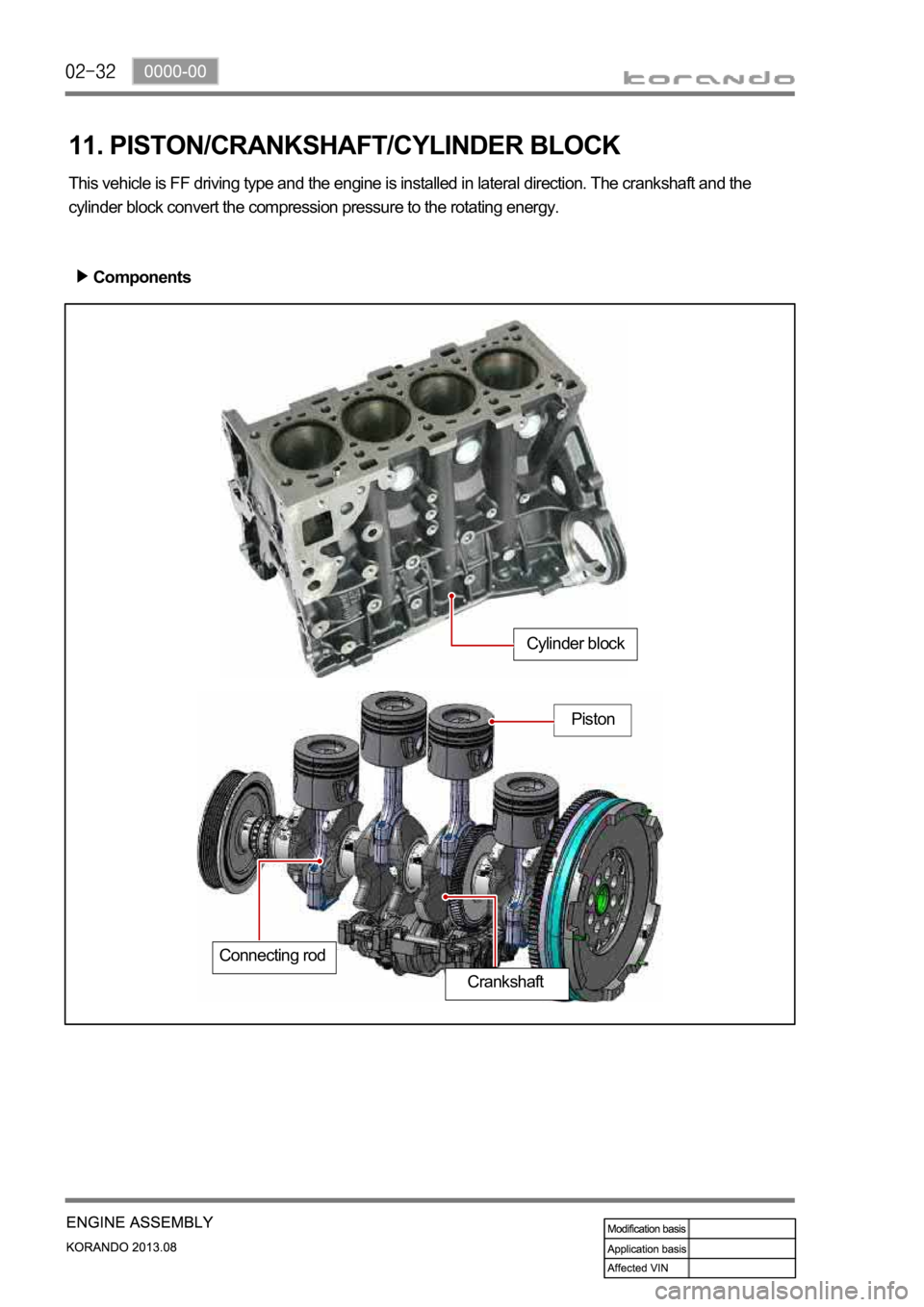
11. PISTON/CRANKSHAFT/CYLINDER BLOCK
This vehicle is FF driving type and the engine is installed in lateral direction. The crankshaft and the
cylinder block convert the compression pressure to the rotating energy.
Components
Cylinder block
Piston
Connecting rod
Crankshaft
Page 247 of 1336
0000-00
(2) Di engine and its expected problems and remedies can be caused by
water in fuel
System supplement against paraffin separation
In case of Diesel fuel, paraffin, one of the elements, can be separated from fuel during winter and then
can stick on the fuel filter blocking fuel flow and causing difficult starting finally. Oil companies supply
summer fuel and winter fuel by differentiating mixing ratio of kerosene and other elements by region and
season. However, above phenomenon can be happened if stations have poor facilities or sell improper
fuel for the season. In case of DI engine, purity of fuel is very important factor to keep internal
preciseness of HP pump and injector.
Accordingly, more dense mesh than conventional fuel filter is used. To prevent fuel filter internal clogging
due to paraffin separation, SYMC is using fuel line that high pressure and temperature fuel injected by
injector returns through fuel filter to have an effect of built-in heater (see fuel system).
System supplement and remedy against water in fuel
As mentioned above, some gas stations supply fuel with excessive than specified water. In the
conventional IDI engine, excessive water in the fuel only causes dropping engine power or engine
hunting. However, fuel system in the DI engine consists of precise components so water in the fuel can
cause malfunctions of HP pump due to poor lubrication of pump caused by poor coating film during high
speed pumping and bacterization (under long period parking). To prevent problems can be caused by
excessive water in fuel, water separator is installed inside of fuel filter. When fuel is passing filter, water
that has relatively bigger specific gravity is accumulated on the bottom of the filter.
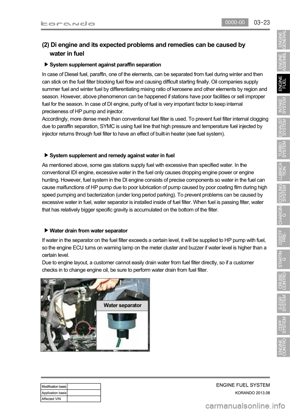
Water drain from water separator
If water in the separator on the fuel filter exceeds a certain level, it will be supplied to HP pump with fuel,
so the engine ECU turns on warning lamp on the meter cluster and buzzer if water level is higher than a
certain level.
Due to engine layout, a customer cannot easily drain water from fuel filter directly, so if a customer
checks in to change engine oil, be sure to perform water drain from fuel filter.
Water separator
Page 252 of 1336
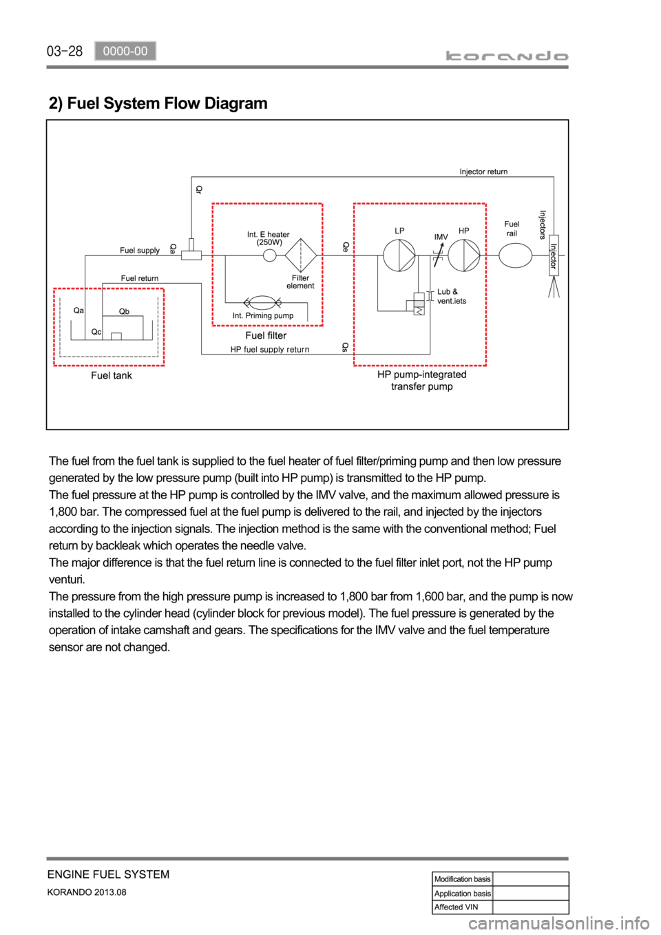
2) Fuel System Flow Diagram
The fuel from the fuel tank is supplied to the fuel heater of fuel filter/priming pump and then low pressure
generated by the low pressure pump (built into HP pump) is transmitted to the HP pump.
The fuel pressure at the HP pump is controlled by the IMV valve, and the maximum allowed pressure is
1,800 bar. The compressed fuel at the fuel pump is delivered to the rail, and injected by the injectors
according to the injection signals. The injection method is the same with the conventional method; Fuel
return by backleak which operates the needle valve.
The major difference is that the fuel return line is connected to the fuel filter inlet port, not the HP pump
venturi.
The pressure from the high pressure pump is increased to 1,800 bar from 1,600 bar, and the pump is now
installed to the cylinder head (cylinder block for previous model). The fuel pressure is generated by the
operation of intake camshaft and gears. The specifications for the IMV valve and the fuel temperature
sensor are not changed.
Page 279 of 1336
0000-00
3. TROUBLESHOOTING
The followings are cautions to take in handling defects of turbocharger, which must be fully aware of.
1) Cautions
After stopping the engine, check whether the bolts on pipe connecting section are
loose as well as the connecting condition of vacuum port and modulator, which is
connected to the actuator.
During idling of the engine, check for leakage in the connecting section of pipe (hoses
and pipes, duct connections, after the turbocharger) by applying soap water. The
leakage condition in the engine block and turbine housing opening can be determined
by the occurrence of abnormal noise of exhaust.
By running the engine at idle speed, abnormal vibration and noise can be checked.
Immediately stop the engine when abnormal vibration and noise is detected and make
thorough inspection whether the turbocharger shaft wheel has any damages as well as
checking the condition of connections between pipes.
In case where the noise of engine is louder than usual, there is possibility of dampness
in the areas related with air cleaner and engine or engine block and turbocharger. And
it could affect the smooth supply of engine oil and discharge.
Check for damp condition in exhaust gas when there is sign of thermal discoloration or
discharge of carbon in connecting area of the duct.
When the engine rotates or in case where there is change in noise level, check for
clogging of air cleaner or air cleaner duct or if there is any significant amount of dust in
the compressor housing.
During the inspection of center housing, inspect inside of the housing by removing the
oil drain pipe to check for sludge generation and its attachment condition at shaft area
or turbine side.
Inspect or replace the air cleaner when the compressor wheel is damaged by inflow of
foreign materials.
Inspect both side of the turbocharger wheel after removing inlet and outlet pipe of the
turbocharger.
- Is the rotation smooth when the rotor is rotated by hand?
- Is the movement of bearing normal?
- Inspect whether there has been any signs of interference between two wheels. 1.
2.
3.
4.
5.
6.
7.
8.
9.
It's important not to drive the engine when the intake manifold hose has been removed.