fuel pressure SSANGYONG KORANDO 2013 Workshop Manual
[x] Cancel search | Manufacturer: SSANGYONG, Model Year: 2013, Model line: KORANDO, Model: SSANGYONG KORANDO 2013Pages: 1336, PDF Size: 92.18 MB
Page 424 of 1336
0000-00
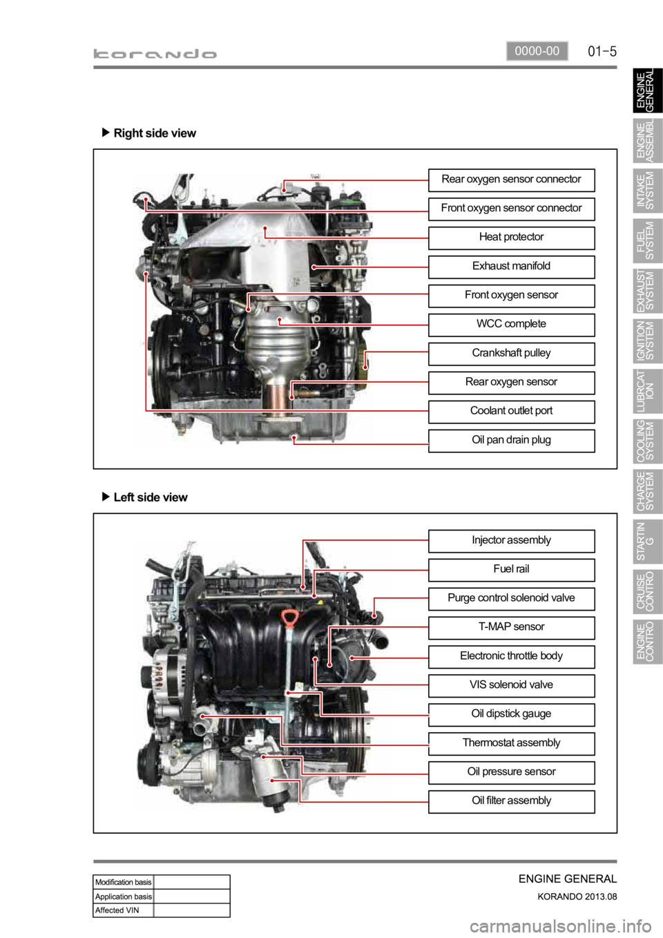
Right side view
Left side view
Rear oxygen sensor connector
Front oxygen sensor connector
Exhaust manifoldHeat protector
Front oxygen sensor
WCC complete
Crankshaft pulley
Oil pan drain plug
Rear oxygen sensor
Coolant outlet port
Injector assembly
Fuel rail
T-MAP sensor Purge control solenoid valve
Electronic throttle body
VIS solenoid valve
Oil dipstick gauge
Oil filter assembly
Thermostat assembly
Oil pressure sensor
Page 428 of 1336
0000-00
5) Guidelines on Engine Service
(1) Cautions before service works
Make sure to disconnect the negative (-) cable from the battery to prevent any damage to electric
systems.
Make sure to clean the working area and to prepare the necessary tools before service works.
Always place the ignition switch to OFF position if not required. Otherwise, there could be unexpected
damage to electric devices or personal injuries due to short-circuit.
To prevent the foreign material from entering into the fuel injection system, completely seal the inlets o
f
HP pump, fuel hoses and high pressure pipes.
To remoev the engine, use the dedicated equipments such as engine jack, transmission jack, engine
stand and engine crane. -
-
-
-
-
(2) Engine and accessories
When disassembling the engine, related parts (bolts, gaskets, etc.) should be stored as a set.
Clean the components completely with engine oil before assembling if needed.
Fully drain the engine oil, coolant and fuel from the vehicle and seal the inlets with the plugs before
removing the engine.
All the interference should be eliminated before removing the engine. -
-
-
- To prevent the personal injuries and vehicle damages that can be caused by mistakes during service
and to provide the optimized performance and safety after service works, the service technicials must
keep the basic cautions and service guidelines below. These could be easily forgotten during service
works.
Engine has a lot of precise components. The specified tightening torque and correct procedures should
be kept during service works. And, the working area is always clean and well prepared.
To prevent any damage to electric systems, make sure to disconnect the negative (-) cable from the
battery and place the ignition switch to OFF position before servicing.
Use only the specified parts with same ratings when replacing the electric devices. Check the
grounds and connections for looseness. -
-
(3) Electric devices
Extraordinary care should be taken when servicing the electric systems. Currently, the engine uses a lot
of electric devices. Short circuit and poor contact may cause the low engine performance, incomplete
combustion and other abnormalities.
When working with the fuel or oil systems in enclosed area, always keep the working area well-
ventilated and never allow anybody to smoke.
Gaskets and seals on the fuel and oil systems should be replaced with new ones. All bolts and nuts
should be tightened as specified.
Make sure to check the connections for leak after installation. -
-
-
(4) Fuel and lubrication system
Page 439 of 1336
3. GUIDELINES ON ENGINE SERVICE
G20DF engine is for FF (Front Engine Front Drive) type vehicle. Therefore, there are some deferent
maintenance and repair works compared to the engine for FR (Front Engine Rear Drive) type vehicle.
For safe and correct works, you must observe the working procedures and instructions in this manual.
And, use the designated tools as follow:
: Power train mounting stand / Engine hanger / Engine stand / Heavy duty engine jack.
Cautions before service works
G20DF engine is FF (Front Engine Front Drive) type engine, and the engine and transmission are
integrated in a same module. Remember that there are many differences compared to
conventional engine in FR (Front Engine Rear Drive) type SUV vehicle.
To remove the engine, use the dedicated equipments such as engine jack, transmission jack,
engine stand and engine crane (1 ton).
To prevent the engine from abruptly starting during service in engine compartment, never allow
anybody to stay in the vehicle.
Make sure to disconnect the negative (-) cable from the battery to prevent any damage to electric
systems.
Make sure to clean the working area and to prepare the necessary tools before service works.
Always place the ignition switch to OFF position if not required. Otherwise, there could be
unexpected damage to electric devices or personal injuries due to short-circuit..
To prevent the foreign material from entering into the fuel injection system, completely seal the
inlets of HP pump, fuel hoses and high pressure pipes.
Do not remove the engine while supporting the oil pan with a jack. -
-
-
-
-
-
-
Lifting up the vehicle
Before lifting up the vehicle with a lift, correctly support the lifting points.
To prevent the vehicle from rolling down, put the chocks under the tires (when using a 4-post lift).
Make sure to support the correct lifting points (when using a 2-post lift). -
-
-
Page 440 of 1336
1116-01
Engine and accessories
Engine has a lot of precise components. The specified tightening torque and correct procedures should
be kept during service works. And, the working area is always clean and well prepared.
When disassembling the engine, related parts (bolts, gaskets, etc.) should be stored as a set.
Carefully read the disassembly and reassembly procedures in this manual before starting the
works.
Clean the components completely with engine oil before assembling if needed.
Fully drain the engine oil, coolant and fuel from the vehicle and seal the inlets with the plugs before
removing the engine.
All the interference should be eliminated before removing the engine. -
-
-
-
Tightening the fastener
When reassembling the parts to G20DF, use the angle tightening as a final step.
1. Clean the mating surfaces before tightening.
2. Place the marks with paint to tighten by angle if the angle wrench is not available. Exhaust system
Wear the protective gloves before removing the exhaust pipe.
The exhaust pipe is very hot immediately after stopping th engine. Check if the exhaust pipe is fully
cooled down before servicing the exhaust system. -
-
Cooling system
Scalding hot coolant and steam could be blown out under pressure, which could cause serious
injury. Never remove the coolant reservoir cap when the engine and the radiator are hot. -
The position and direction of the componets is based on the rear view.
Do not tighten the fasteners with excessive force. Especially, the threads of cylinder block could be
damaged.
The self screw bolt makes the thread itself when tightening it. Do not apply excessive force.
Do not reuse the bolt that has been tightened with angle tightening method.
Page 441 of 1336
Fuel and engine oil system
The engine oil and fuel damages the painted surfaces and rubber material of the vehicle.
Disconnect the negative cable from the battery before servicing the fuel system, and prepare the
service plug grip.
When working with the fuel or oil systems in enclosed area, always keep the working area well-
ventilated and never allow anybody to smoke.
Do not allow the gasoline to contact to rubber or leather parts.
Carefully separate the pipe between high pressure fuel pump and fuel injector so that any fuel can
be spilled out.
Fully release the pressure from the fuel system before removing any parts of fuel system.
To release the fuel pressure in high pressure line, let the engine fully cool down.
Gaskets and seals on the fuel and oil systems should be replaced with new ones. All bolts and nuts
should be tightened as specified.
Prolonged exposure to the engine oil make cause a skin cancer or an irritation.
Used engine cotains the hazardous material that may cause the skin cancer. Do not allow the used
engine to make contact with your skin.
Make sure to wear the protection gloves and goggle when handling the engine oil. If contact
happens, rinse affected areas immediately with plenty of water. Do not wash it with gasoline or
solvent. If irritation persists, consult a doctor.
Improperly disposed engine oil can pollute the environment. Dispose the used engine oil and oil
filter in accordance with local environmental regulations.
Make sure to check the connections for leak after installation. -
-
-
-
-
-
-
-
-
-
-
-
Electric devices
To prevent any damage to electric systems, make sure to disconnect the negative (-) cable from the
battery and place the ignition switch to OFF position before servicing.
Use only the specified parts with same ratings when replacing the electric devices. Check the
grounds and connections for looseness. -
- Extraordinary care should be taken when servicing the electric systems. Currently, the engine uses a lot
of electric devices. Short circuit and poor contact may cause the low engine performance, incomplete
combustion and other abnormalities.
Page 452 of 1336
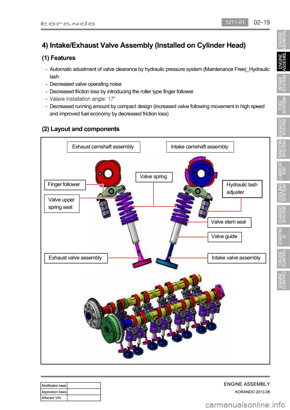
1211-01
4) Intake/Exhaust Valve Assembly (Installed on Cylinder Head)
(1) Features
Automatic adustment of valve clearance by hydraulic pressure system (Maintenance Free)_Hydraulic
lash
Decreased valve operating noise
Decreased friction loss by introducing the roller type finger follower
Decreased running amount by compact design (increased valve following movement in high speed
and improved fuel economy by decreased friction loss) -
-
-
-
-
(2) Layout and components
Intake camshaft assemblyExhaust camshaft assembly
Valve stem seal
Valve upper
spring seat
Valve guide
Hydraulic lash
adjuster
Exhaust valve assembly
Valve spring
Finger follower
Intake valve assembly
Page 480 of 1336
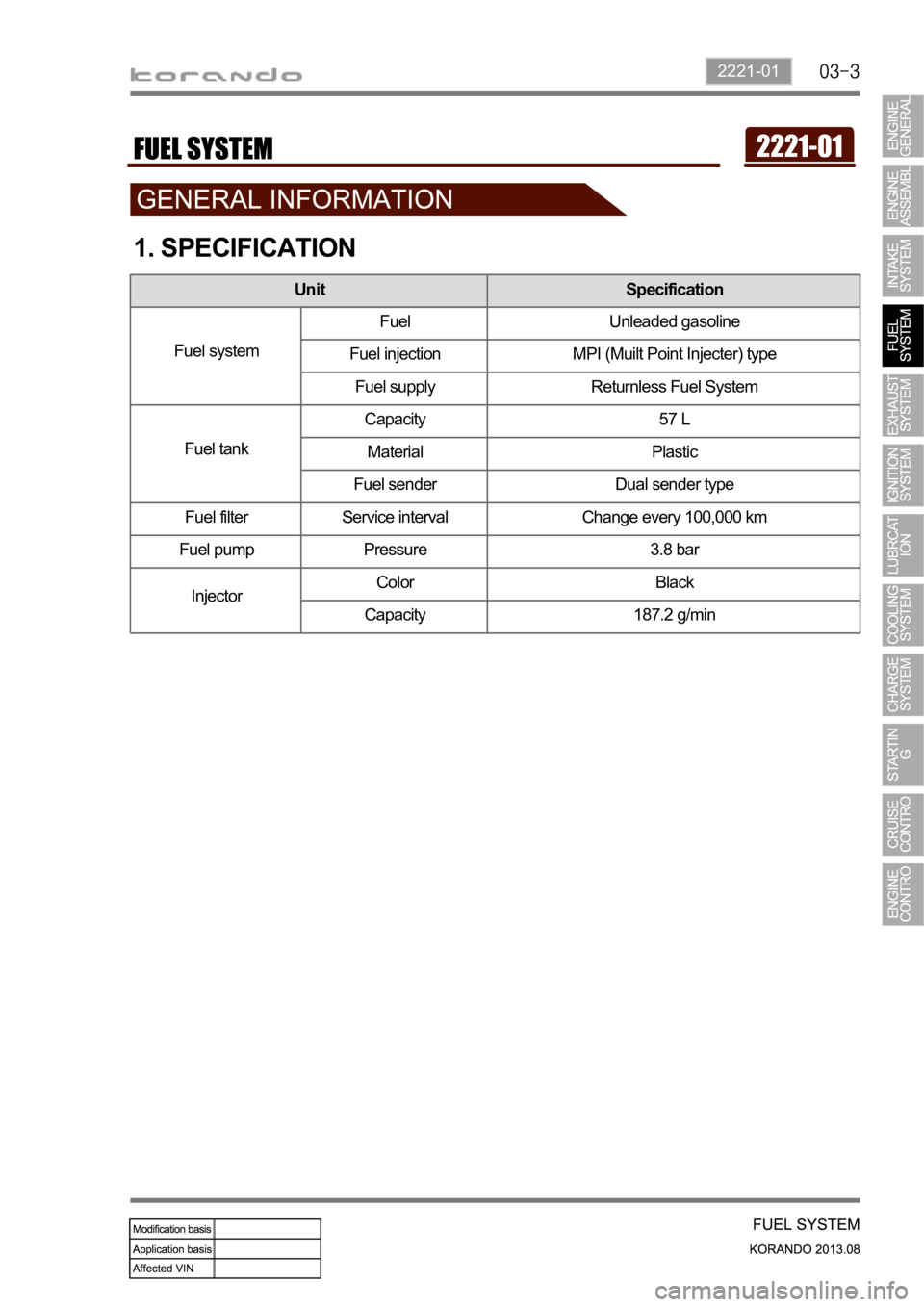
2221-01
1. SPECIFICATION
Unit Specification
Fuel systemFuel Unleaded gasoline
Fuel injection MPI (Muilt Point Injecter) type
Fuel supply Returnless Fuel System
Fuel tankCapacity 57 L
Material Plastic
Fuel sender Dual sender type
Fuel filter Service interval Change every 100,000 km
Fuel pump Pressure 3.8 bar
InjectorColor Black
Capacity 187.2 g/min
Page 483 of 1336
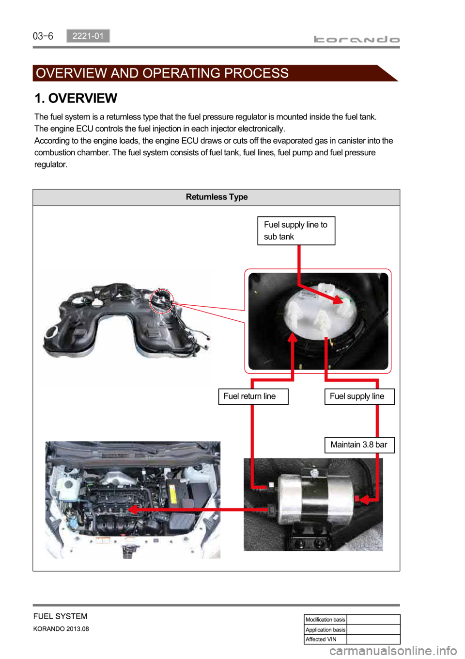
Returnless Type
1. OVERVIEW
The fuel system is a returnless type that the fuel pressure regulator is mounted inside the fuel tank.
The engine ECU controls the fuel injection in each injector electronically.
According to the engine loads, the engine ECU draws or cuts off the evaporated gas in canister into the
combustion chamber. The fuel system consists of fuel tank, fuel lines, fuel pump and fuel pressure
regulator.
Fuel supply line to
sub tank
Fuel return lineFuel supply line
Maintain 3.8 bar
Page 858 of 1336
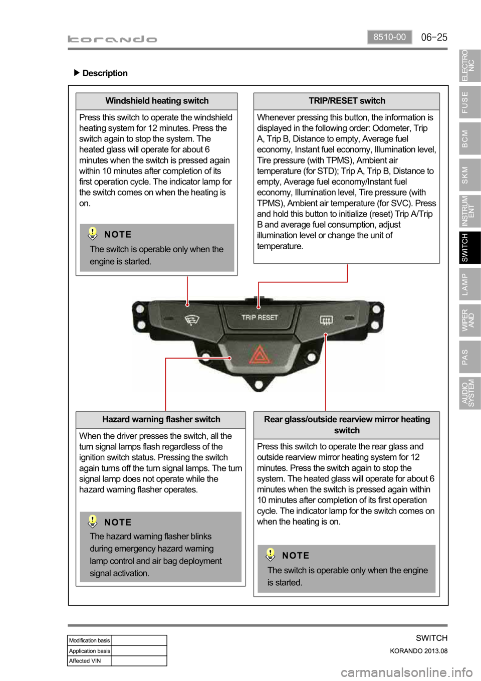
8510-00
Windshield heating switch
Press this switch to operate the windshield
heating system for 12 minutes. Press the
switch again to stop the system. The
heated glass will operate for about 6
minutes when the switch is pressed again
within 10 minutes after completion of its
first operation cycle. The indicator lamp for
the switch comes on when the heating is
on.
Hazard warning flasher switch
When the driver presses the switch, all the
turn signal lamps flash regardless of the
ignition switch status. Pressing the switch
again turns off the turn signal lamps. The turn
signal lamp does not operate while the
hazard warning flasher operates.
TRIP/RESET switch
Whenever pressing this button, the information is
displayed in the following order: Odometer, Trip
A, Trip B, Distance to empty, Average fuel
economy, Instant fuel economy, Illumination level,
Tire pressure (with TPMS), Ambient air
temperature (for STD); Trip A, Trip B, Distance to
empty, Average fuel economy/Instant fuel
economy, Illumination level, Tire pressure (with
TPMS), Ambient air temperature (for SVC). Press
and hold this button to initialize (reset) Trip A/Trip
B and average fuel consumption, adjust
illumination level or change the unit of
temperature.
Description
Rear glass/outside rearview mirror heating
switch
Press this switch to operate the rear glass and
outside rearview mirror heating system for 12
minutes. Press the switch again to stop the
system. The heated glass will operate for about 6
minutes when the switch is pressed again within
10 minutes after completion of its first operation
cycle. The indicator lamp for the switch comes on
when the heating is on.
The switch is operable only when the engine
is started.
The hazard warning flasher blinks
during emergency hazard warning
lamp control and air bag deployment
signal activation.
The switch is operable only when the
engine is started.
Page 1016 of 1336
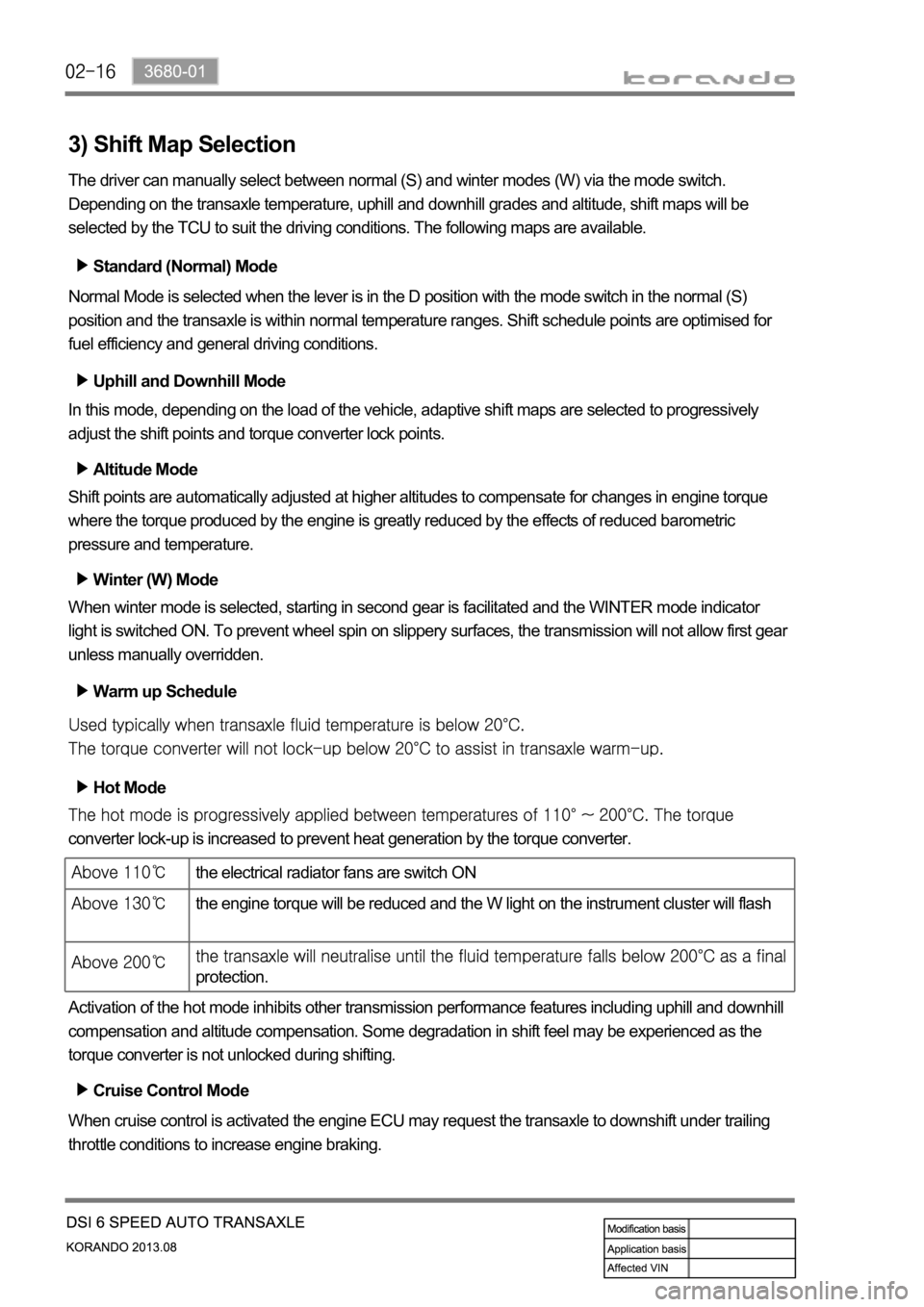
3) Shift Map Selection
The driver can manually select between normal (S) and winter modes (W) via the mode switch.
Depending on the transaxle temperature, uphill and downhill grades and altitude, shift maps will be
selected by the TCU to suit the driving conditions. The following maps are available.
Standard (Normal) Mode
Normal Mode is selected when the lever is in the D position with the mode switch in the normal (S)
position and the transaxle is within normal temperature ranges. Shift schedule points are optimised for
fuel efficiency and general driving conditions.
Uphill and Downhill Mode
In this mode, depending on the load of the vehicle, adaptive shift maps are selected to progressively
adjust the shift points and torque converter lock points.
Altitude Mode
Shift points are automatically adjusted at higher altitudes to compensate for changes in engine torque
where the torque produced by the engine is greatly reduced by the effects of reduced barometric
pressure and temperature.
Winter (W) Mode
When winter mode is selected, starting in second gear is facilitated and the WINTER mode indicator
light is switched ON. To prevent wheel spin on slippery surfaces, the transmission will not allow first gear
unless manually overridden.
Warm up Schedule
Hot Mode
converter lock-up is increased to prevent heat generation by the torque converter.
Activation of the hot mode inhibits other transmission performance features including uphill and downhill
compensation and altitude compensation. Some degradation in shift feel may be experienced as the
torque converter is not unlocked during shifting.
Cruise Control Mode
When cruise control is activated the engine ECU may request the transaxle to downshift under trailing
throttle conditions to increase engine braking.
the electrical radiator fans are switch ON
the engine torque will be reduced and the W light on the instrument cluster will flash
protection.