display SSANGYONG KORANDO 2013 Workshop Manual
[x] Cancel search | Manufacturer: SSANGYONG, Model Year: 2013, Model line: KORANDO, Model: SSANGYONG KORANDO 2013Pages: 1336, PDF Size: 92.18 MB
Page 980 of 1336

Ensure that the connection or disconnection between the audio system and the USB memory/iPod
is carried out only when the engine is switched off. If the engine is switched on or off while the USB
memory is connected or disconnected, the USB memory may be damaged or not operate normally.
The audio system may not recognize some USB memory depending on the comparability or
condition. Check whether the USB memory operates normally in the vehicle before using it.
Take great care to ensure that the USB connection does not come in contact with the human body
or any object and the USB linking cable does not disturb a safe driving.
When you connect and disconnect the USB memory to the audio system several times in a short
periods, it may cause the USB memory to corrupt. If you particularly disconnect USB memory
during playback, it may be broken or operate incorrectly.
When you use the USB device for charging or heating by using the USB terminal on the audio
system, it may cause the system to deteriorate or fail.
iPod is a registered trademark of Apple Inc.
This audio system supports only the following iPod products: iPod Nano /iPod/iPod Touch/ iPhone.
This audio system may not support some iPod/iPhone products.
Always use the linking cable included with the iPod product when connecting it to the audio system.
The other cables may not be compatible and cause the audio system to fail.
In some cases, the iPod product may be damaged or not operate normally when the engine is
switched on while it is connected to the audio system. When not in use, always disconnect the iPod
product with the engine switched off.
When you use the iPod by connecting it to the audio system, the playback function and information
display may differ from original.
The iPod product can't be recharged using a iPod linking cable. -
-
-
-
-
-
-
-
-
-
-
-Cautions for using USB memory/iPod
Page 982 of 1336

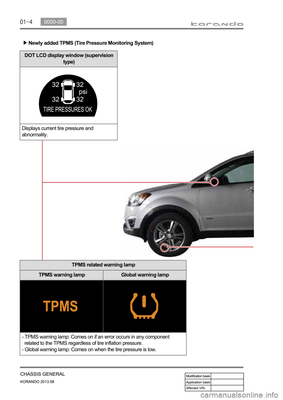
Newly added TPMS (Tire Pressure Monitoring System)
TPMS related warning lamp
TPMS warning lamp Global warning lamp
- TPMS warning lamp: Comes on if an error occurs in any component
related to the TPMS regardless of tire inflation pressure.
- Global warning lamp: Comes on when the tire pressure is low.
DOT LCD display window (supervision
type)
Displays current tire pressure and
abnormality.
Page 1012 of 1336

1st Gear State
The 1st gear state will display on the
instrument cluster. Unlike the normal 1st gear,
engine braking will be available in this manual
1st state. -
2nd Gear State
The 2nd gear state will display on the
instrument cluster. 2-1 automatic kick-down
shifts are available. 2nd gear has engine
braking available. -
3rd Gear State
The 3rd gear state will display on the
instrument cluster. 3-2 and 3-1 automatic
kick-down shifts are available. 3rd gear has
engine braking available. -
4th Gear State
The 4th gear state will display on the
instrument cluster. 4-3 and 4-2 automatic
kick-down shifts are available. 4th gear has
engine braking available. -
5th Gear State
The 5th gear state will display on the
instrument cluster. 5-4 and 5-3 automatic
kick-down shift is available. 5th gear has
engine braking available. -
6th Gear State
The 6th gear state will display on the
instrument cluster. 6-5 and 6-4 automatic
kick-down shifts are available. 6th gear has
engine braking available. -
STD type
SVC type
Page 1013 of 1336

3680-01
4. LIMP HOME MODE
When the transaxle is defective
In the event of a system fault, the TCU also provides for failure mode effect control (FMEC) to maintain
maximum functional operation of the transaxle.
In the event of a total loss of control or electrical power, the basic transaxle functions (Park, Reverse,
Neutral and Drive) are retained. The 4th and reverse gear ratios with the torque converter clutch in the
unlocked state are the retained gear states the hydraulic system supports without any electrical
assistance.
The TCU communicates with other vehicle electronic control modules by the controller area network
(CAN). If a major fault develops, the transaxle may automatically operate in a "limp home" (failure)
mode to enable the vehicle to be driven to an authorized dealer for repair.
The TCU also provides for transaxle diagnostics, which meet the requirements of OBD II legislation,
monitoring all components which may effect vehicle emissions. 1.
2.
3.
4.
When the transaxle overheats
Limp home mode may also be engaged if the battery charge falls below 8V.
If the transaxle overheats, the shift patterns will automatically change to enable improved transaxle
cooling.
During transaxle overheat, the instrument cluster transaxle selector position display and the over
cluster until normal transaxle operating temperature is reached. 1.
2.
3.
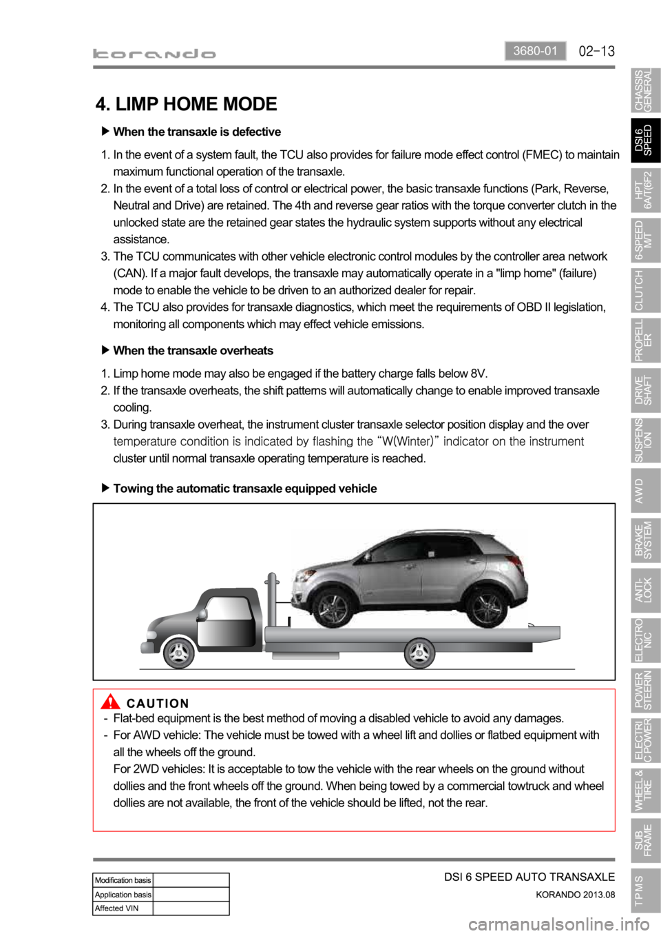
Towing the automatic transaxle equipped vehicle
Flat-bed equipment is the best method of moving a disabled vehicle to avoid any damages.
For AWD vehicle: The vehicle must be towed with a wheel lift and dollies or flatbed equipment with
all the wheels off the ground.
For 2WD vehicles: It is acceptable to tow the vehicle with the rear wheels on the ground without
dollies and the front wheels off the ground. When being towed by a commercial towtruck and wheel
dollies are not available, the front of the vehicle should be lifted, not the rear. -
-
Page 1041 of 1336

3660-01
1st Gear State
The 1st gear state will display on the
instrument cluster. Unlike the normal 1st gear,
engine braking will be available in this manual
1st state. -
2nd Gear State
The 2nd gear state will display on the
instrument cluster. 2nd gear has engine braking
available. -
3rd Gear State
The 3rd gear state will display on the
instrument cluster. 3rd gear has engine
braking available. -
4th Gear State
The 4th gear state will display on the
instrument cluster. 4th gear has engine
braking available. -
5th Gear State
The 5th gear state will display on the
instrument cluster. 5th gear has engine
braking available. -
6th Gear State
The 6th gear state will display on the
instrument cluster. 6th gear has engine
braking available. -
STD type
SVC type
Page 1172 of 1336

4190-00
3. CAUTIONS
The tire pressure values displayed on the instrument cluster are sent from the wheel modules after
the vehicle is driven for a period of time. Therefore, they are not displayed at initial start (more than
20 minutes have elapsed after ignition off). It can be displayed after 10 minutes of driving at speed of
20 km/h or higher. -
The TPMS uses a radio frequency and a high frequency band between the wheel module and the
TPMS ECU for communication.
Therefore, if the vehicle is equipped with the electronic equipment such as mobile camera monitor
or the vehicle is passing through the area with a strong electromagnetic field, the system may not
operate normally.
For the vehicle equipped with the TPMS, the TPMS warning lamp on the instrument cluster comes
on and pressure values on the EL display is displayed as bars (--) after driving for a certain period of
time if a newly installed tire is not equipped with the wheel module. -
-
At initial startDisplay pressure value after
detecting
position automatically
Standard type
Supervision type
Page 1175 of 1336

Instrument cluster display related to TPMS (with standard)
DOT LCD display TPMS warning lamp Global warning lamp
2. LAYOUT 1. OVERVIEW
The TPMS is used to reduce the accident rate, enhance driving stability and avoid an unnecessary fuel
consumption and tire wear by monitoring the tire pressure and temperature to inform the driver of tire
pressure information and its status through the instrument cluster. The wheel module fitted in the tire
transmits the internal data for the tire to the TPMS ECU periodically through the wireless transmission.
The TPMS ECU can detect the positions of the wheel modules fitted to each wheel automatically and
sends the signal on tire condition through the CAN line to the instrument cluster so that the driver can
identify the wheel module in question.
Instrument cluster display related to TPMS (with supervision)
DOT LCD display TPMS warning lamp Global warning lamp
Page 1178 of 1336

4190-00
4. TPMS PRESSURE VALUE DISPLAYING PROCESS
The TPMS ECU receives the tire pressure value from the wheel module through the wireless
transmission once every about 30 seconds and displays the pressure value on the instrument cluster
through CAN line.
Under normal circumstances, it transmits the tire pressure value and temperature value together
with its ID (Identification) once every about 30 seconds to reduce the load on the wheel module's
battery. But, in the event of emergency or situation which should give a warning to the driver, it
transmits the data once every about 1 second. Since the battery consumption will be increased
rapidly until the data transmission interval will be returned to normal after certain length of time,
adjust the tire pressure to the specified one after rectifying the cause.
The tire pressure is displayed through the following sequences, which occur at the same
time.
Wheel module detection
(Auto learning)This is a step which receives an ID signal from the wheel module fitted
to the vehicle. When the wheel module sends the signal about twice
every 1 minute, each wheel module will be identified.
Wheel module mounting
location detection
(Auto location)The TPMS ECU check which wheel module is installed to which tire.
Page 1179 of 1336

5. LOW TIRE PRESSURE WARNING
If the tire pressure is less than 13% of the proper value calculated by the TPMS ECU depending on the
ambient temperature for more than 8 minutes, the 1st low tire pressure warning is given. And, if the tire
pressure is less than 20% for more than 4 minutes, the 2nd warning is given. At this time, the "Check
tire" message is displayed on the DOT LCD display and the global warning lamp comes on.
ECU receives the ambient temperature signal from the instrument cluster through CAN
communication and calculates the proper tire pressure to correct it since the tire pressure changes
depending on the ambient temperature.
Page 1181 of 1336

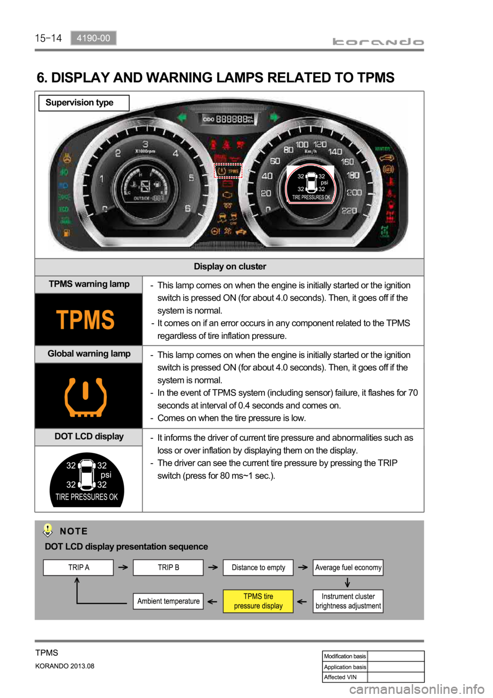
Display on cluster
TPMS warning lamp
Global warning lamp
DOT LCD display
6. DISPLAY AND WARNING LAMPS RELATED TO TPMS
This lamp comes on when the engine is initially started or the ignition
switch is pressed ON (for about 4.0 seconds). Then, it goes off if the
system is normal.
It comes on if an error occurs in any component related to the TPMS
regardless of tire inflation pressure. -
-
This lamp comes on when the engine is initially started or the ignition
switch is pressed ON (for about 4.0 seconds). Then, it goes off if the
system is normal.
In the event of TPMS system (including sensor) failure, it flashes for 70
seconds at interval of 0.4 seconds and comes on.
Comes on when the tire pressure is low. -
-
-
It informs the driver of current tire pressure and abnormalities such as
loss or over inflation by displaying them on the display.
The driver can see the current tire pressure by pressing the TRIP
switch (press for 80 ms~1 sec.). -
-
DOT LCD display presentation sequence
Supervision type