wheel SSANGYONG KORANDO 2013 Workshop Manual
[x] Cancel search | Manufacturer: SSANGYONG, Model Year: 2013, Model line: KORANDO, Model: SSANGYONG KORANDO 2013Pages: 1336, PDF Size: 92.18 MB
Page 1000 of 1336
4) Basic Inspection
(1) Horn operation
Listen for the horn sound when pressing the horn pad on the steering wheel. -
(2) Brake operation
Check if there is any abnormal noise, unusually long braking distance, or uneven braking force. If the
brake warning lamp does not go out even after starting the engien or are flashing during driving,
have the brake system checked immediately.
Check the brake pipes and hoses for connection, oil leak, crack or interference after changing the
position of tires. When replacing the tires, check the brake disc for surface condition and wear.
Check the parking brake cable and brake operation. Shorten the checking interval if the parking
brake is used frequently. -
-
-
(3) Exhaust system
Be aware to any changes in sound or smell from the exhaust system. These may be caused by leak or
overheat. Have the exhaust system checked and repaired immediately.
Inspect the exhaust system including catalytic converter. Inspect all the components and body frame
near the exhaust system. -
-
(4) Tires
Unusual vibration of the steering wheel and seats or pulling to one side on the straight and level roads
may indicates the uneven tire inflation pressure or poor wheel balance. -
(5) Steering and suspension system
Inspect the front and rear suspension and the steering system for damage, looseness or missing
parts, signs of wear or lack of lubrication. Inspect the power steering line and the hoses for
connection, leak, crack and chafing. Inspect the drive axle boot and seals for damage, tear or leak.
Replace or repair the system if necessary. -
(6) Engine oil
Check the oil level when the engine is still warm and add the specified engine oil if necessary. -
(7) Coolant
Check the coolant level in the coolant reservoir, coolant conditions (contamination, foreign material),
and hoses for damage and leak. Replace or add the Ssangyong genuine coolant, if needed. -
(8) Engine drive belt
Check all drive belts on the engine for wear, crack and looseness. Retighten or replace the belt, if
needed. -
Page 1003 of 1336
3680-01
1. GENERAL INFORMATION
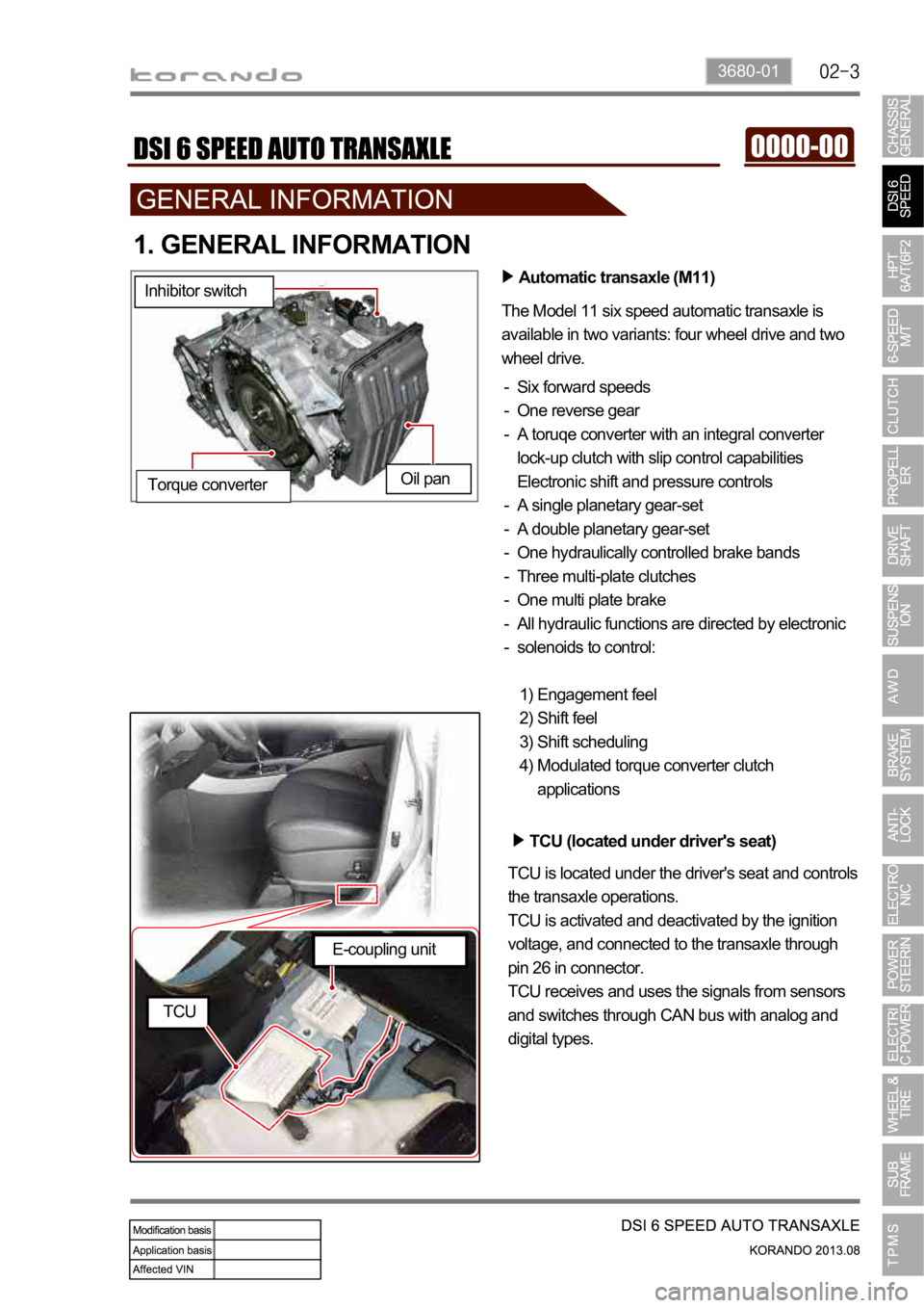
Automatic transaxle (M11)
The Model 11 six speed automatic transaxle is
available in two variants: four wheel drive and two
wheel drive.
Six forward speeds
One reverse gear
A toruqe converter with an integral converter
lock-up clutch with slip control capabilities
Electronic shift and pressure controls
A single planetary gear-set
A double planetary gear-set
One hydraulically controlled brake bands
Three multi-plate clutches
One multi plate brake
All hydraulic functions are directed by electronic
solenoids to control: -
-
-
-
-
-
-
-
-
-
Engagement feel
Shift feel
Shift scheduling
Modulated torque converter clutch
applications 1)
2)
3)
4) Inhibitor switch
Oil pan
Torque converter
TCU (located under driver's seat)
TCU is located under the driver's seat and controls
the transaxle operations.
TCU is activated and deactivated by the ignition
voltage, and connected to the transaxle through
pin 26 in connector.
TCU receives and uses the signals from sensors
and switches through CAN bus with analog and
digital types.
E-coupling unit
TCU
Page 1004 of 1336
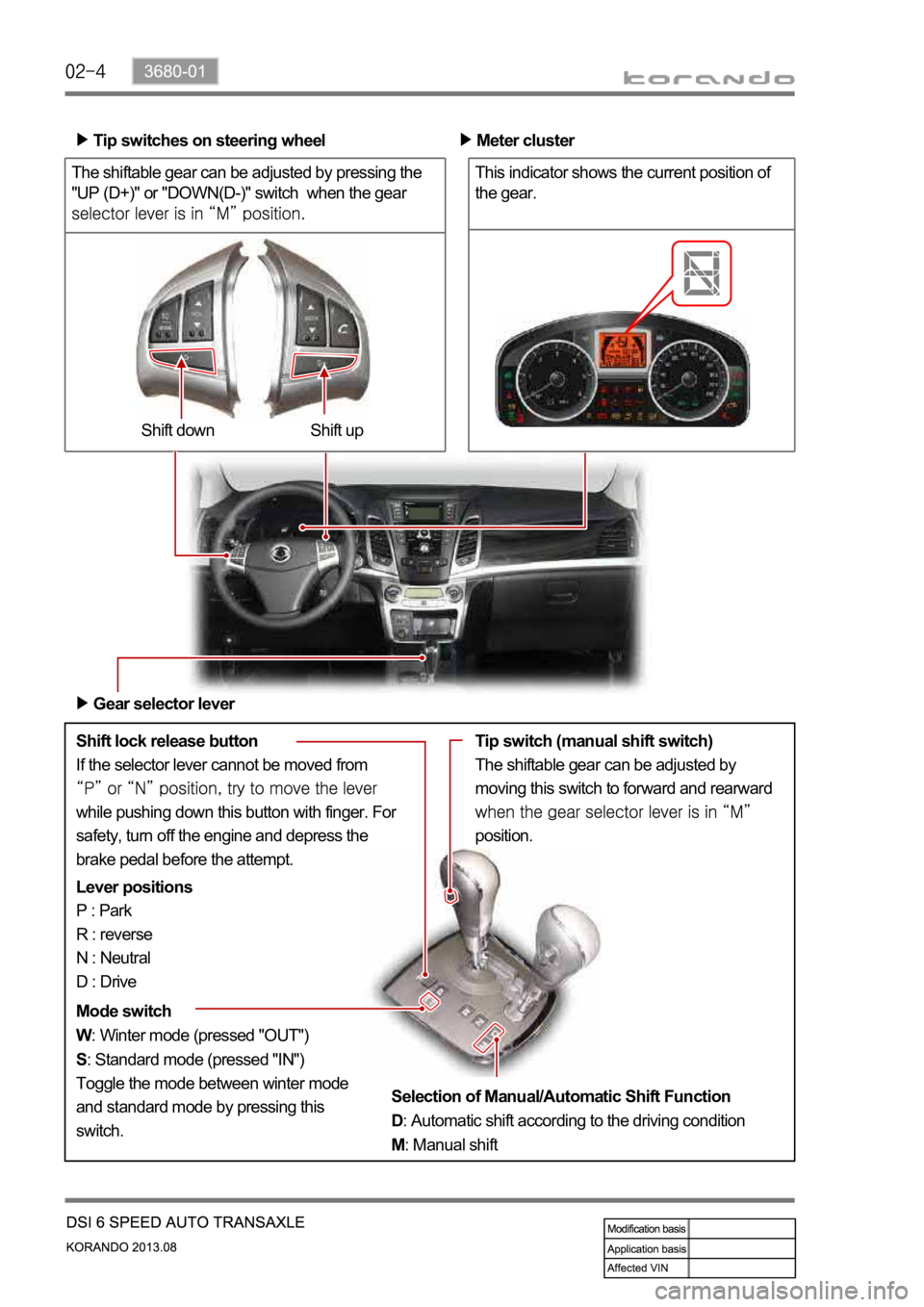
The shiftable gear can be adjusted by pressing the
"UP (D+)" or "DOWN(D-)" switch when the gear
Shift lock release button
If the selector lever cannot be moved from
while pushing down this button with finger. For
safety, turn off the engine and depress the
brake pedal before the attempt.Shift up Shift down Tip switches on steering wheel
Meter cluster
This indicator shows the current position of
the gear.
Gear selector lever
Lever positions
P : Park
R : reverse
N : Neutral
D : Drive
Mode switch
W: Winter mode (pressed "OUT")
S: Standard mode (pressed "IN")
Toggle the mode between winter mode
and standard mode by pressing this
switch.Tip switch (manual shift switch)
The shiftable gear can be adjusted by
moving this switch to forward and rearward
position.
Selection of Manual/Automatic Shift Function
D: Automatic shift according to the driving condition
M: Manual shift
Page 1013 of 1336
3680-01
4. LIMP HOME MODE
When the transaxle is defective
In the event of a system fault, the TCU also provides for failure mode effect control (FMEC) to maintain
maximum functional operation of the transaxle.
In the event of a total loss of control or electrical power, the basic transaxle functions (Park, Reverse,
Neutral and Drive) are retained. The 4th and reverse gear ratios with the torque converter clutch in the
unlocked state are the retained gear states the hydraulic system supports without any electrical
assistance.
The TCU communicates with other vehicle electronic control modules by the controller area network
(CAN). If a major fault develops, the transaxle may automatically operate in a "limp home" (failure)
mode to enable the vehicle to be driven to an authorized dealer for repair.
The TCU also provides for transaxle diagnostics, which meet the requirements of OBD II legislation,
monitoring all components which may effect vehicle emissions. 1.
2.
3.
4.
When the transaxle overheats
Limp home mode may also be engaged if the battery charge falls below 8V.
If the transaxle overheats, the shift patterns will automatically change to enable improved transaxle
cooling.
During transaxle overheat, the instrument cluster transaxle selector position display and the over
cluster until normal transaxle operating temperature is reached. 1.
2.
3.
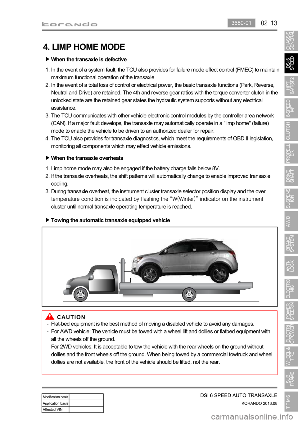
Towing the automatic transaxle equipped vehicle
Flat-bed equipment is the best method of moving a disabled vehicle to avoid any damages.
For AWD vehicle: The vehicle must be towed with a wheel lift and dollies or flatbed equipment with
all the wheels off the ground.
For 2WD vehicles: It is acceptable to tow the vehicle with the rear wheels on the ground without
dollies and the front wheels off the ground. When being towed by a commercial towtruck and wheel
dollies are not available, the front of the vehicle should be lifted, not the rear. -
-
Page 1016 of 1336
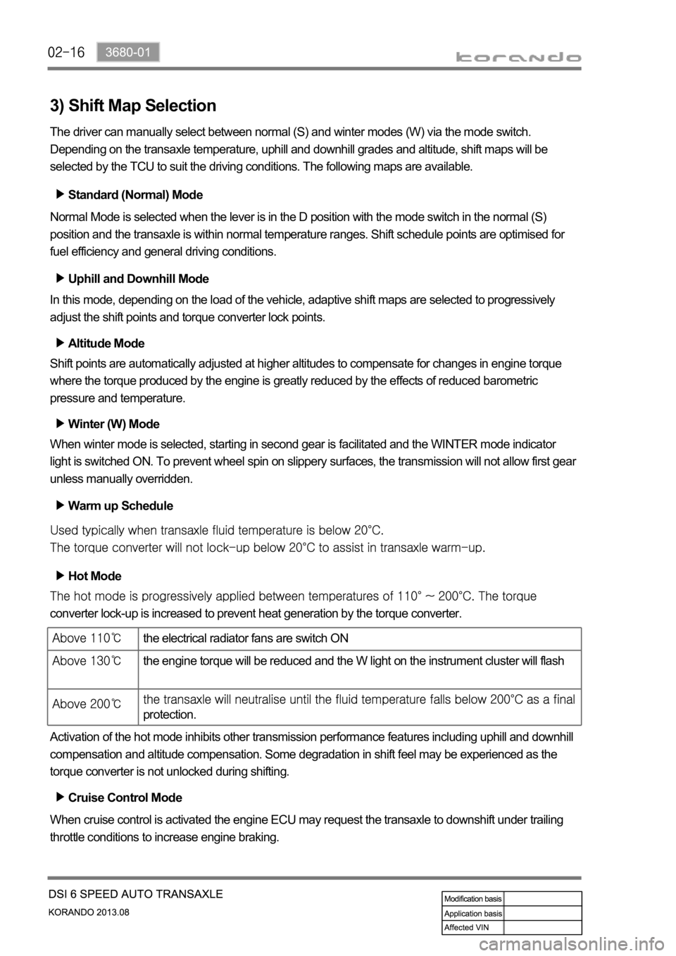
3) Shift Map Selection
The driver can manually select between normal (S) and winter modes (W) via the mode switch.
Depending on the transaxle temperature, uphill and downhill grades and altitude, shift maps will be
selected by the TCU to suit the driving conditions. The following maps are available.
Standard (Normal) Mode
Normal Mode is selected when the lever is in the D position with the mode switch in the normal (S)
position and the transaxle is within normal temperature ranges. Shift schedule points are optimised for
fuel efficiency and general driving conditions.
Uphill and Downhill Mode
In this mode, depending on the load of the vehicle, adaptive shift maps are selected to progressively
adjust the shift points and torque converter lock points.
Altitude Mode
Shift points are automatically adjusted at higher altitudes to compensate for changes in engine torque
where the torque produced by the engine is greatly reduced by the effects of reduced barometric
pressure and temperature.
Winter (W) Mode
When winter mode is selected, starting in second gear is facilitated and the WINTER mode indicator
light is switched ON. To prevent wheel spin on slippery surfaces, the transmission will not allow first gear
unless manually overridden.
Warm up Schedule
Hot Mode
converter lock-up is increased to prevent heat generation by the torque converter.
Activation of the hot mode inhibits other transmission performance features including uphill and downhill
compensation and altitude compensation. Some degradation in shift feel may be experienced as the
torque converter is not unlocked during shifting.
Cruise Control Mode
When cruise control is activated the engine ECU may request the transaxle to downshift under trailing
throttle conditions to increase engine braking.
the electrical radiator fans are switch ON
the engine torque will be reduced and the W light on the instrument cluster will flash
protection.
Page 1030 of 1336
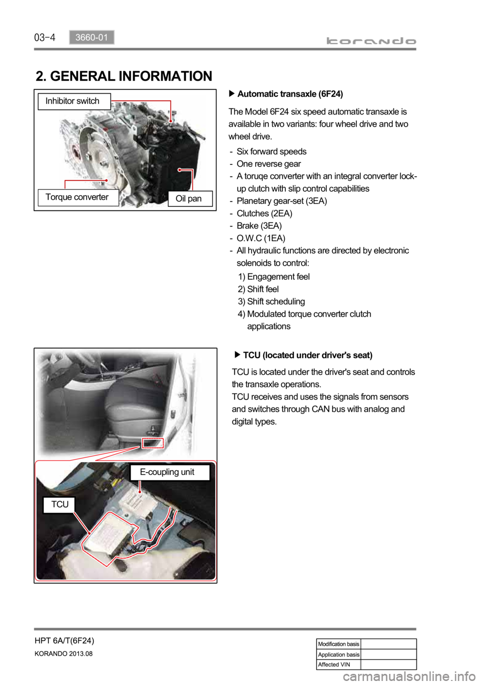
2. GENERAL INFORMATION
Automatic transaxle (6F24)
The Model 6F24 six speed automatic transaxle is
available in two variants: four wheel drive and two
wheel drive.
Six forward speeds
One reverse gear
A toruqe converter with an integral converter lock-
up clutch with slip control capabilities
Planetary gear-set (3EA)
Clutches (2EA)
Brake (3EA)
O.W.C (1EA)
All hydraulic functions are directed by electronic
solenoids to control: -
-
-
-
-
-
-
-
Engagement feel
Shift feel
Shift scheduling
Modulated torque converter clutch
applications 1)
2)
3)
4) Inhibitor switch
Oil pan
Torque converter
TCU (located under driver's seat)
TCU is located under the driver's seat and controls
the transaxle operations.
TCU receives and uses the signals from sensors
and switches through CAN bus with analog and
digital types.
E-coupling unit
TCU
Page 1031 of 1336
3660-01
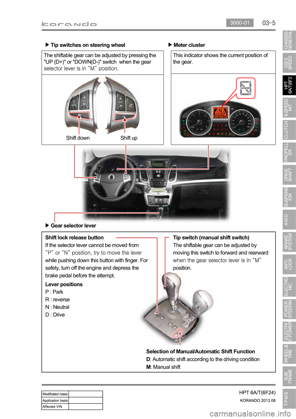
The shiftable gear can be adjusted by pressing the
"UP (D+)" or "DOWN(D-)" switch when the gear
Shift lock release button
If the selector lever cannot be moved from
while pushing down this button with finger. For
safety, turn off the engine and depress the
brake pedal before the attempt.Shift up Shift down Tip switches on steering wheel
Meter cluster
This indicator shows the current position of
the gear.
Gear selector lever
Lever positions
P : Park
R : reverse
N : Neutral
D : DriveTip switch (manual shift switch)
The shiftable gear can be adjusted by
moving this switch to forward and rearward
position.
Selection of Manual/Automatic Shift Function
D: Automatic shift according to the driving condition
M: Manual shift
Page 1042 of 1336
4. LIMP HOME MODE
When the transaxle is defective
In the event of a system fault, the TCU also provides for failure mode effect control (FMEC) to maintain
maximum functional operation of the transaxle. (There are 3 FMEC modes, mechanical limp-home
mode, electrical limp-home mode, limp-home mode C.)
In the event of a total loss of control or electrical power, the basic transaxle functions (Park, Reverse,
Neutral and Drive) are retained. The 4th and reverse gear ratios with the torque converter clutch in the
unlocked state are the retained gear states the hydraulic system supports without any electrical
assistance. (Mechanical limp-home)
If the speed sensor circuit is failed, the gear is fixed to 4th gear, but manual shifting
If the inhibitor switch signals are invalid, shifting to1st and 2nd gear is forbidden. (Limp-home C)
The TCU communicates with other vehicle electronic control modules by the controller area network
(CAN). If a major fault is developed, the transaxle may not accomplish the intelligent shift control. The
TCU controls the transaxle with preset values.
The TCU also provides for transaxle diagnostics, which meet the requirements of OBD II regulation,
monitoring all components which may effect vehicle emissions. 1.
2.
3.
4.
5.
6.
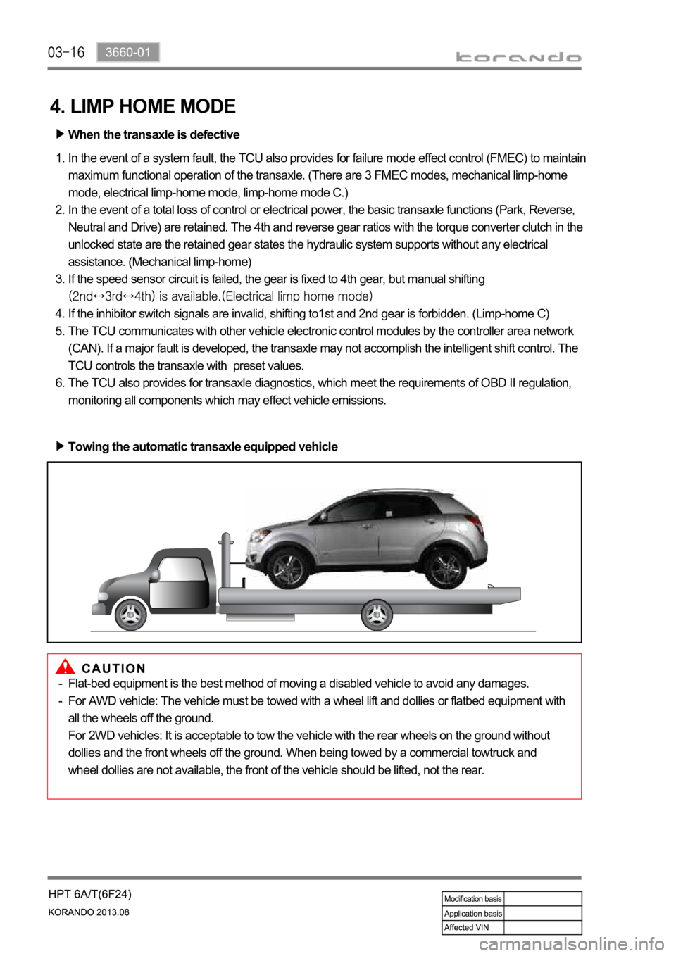
Towing the automatic transaxle equipped vehicle
Flat-bed equipment is the best method of moving a disabled vehicle to avoid any damages.
For AWD vehicle: The vehicle must be towed with a wheel lift and dollies or flatbed equipment with
all the wheels off the ground.
For 2WD vehicles: It is acceptable to tow the vehicle with the rear wheels on the ground without
dollies and the front wheels off the ground. When being towed by a commercial towtruck and
wheel dollies are not available, the front of the vehicle should be lifted, not the rear. -
-
Page 1064 of 1336
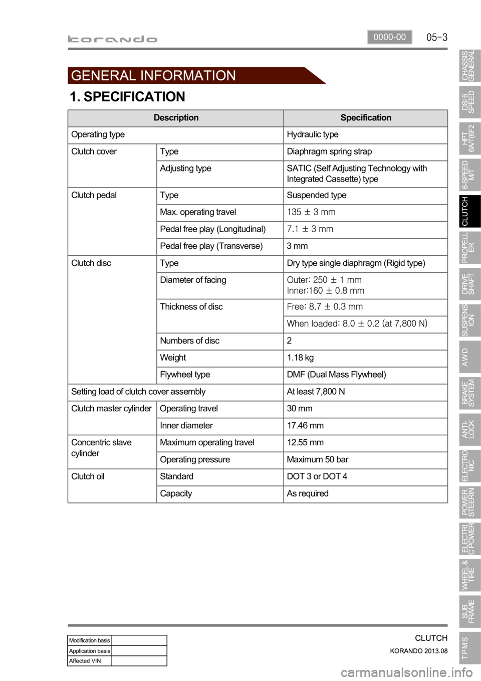
0000-00
1. SPECIFICATION
Description Specification
Operating type Hydraulic type
Clutch cover Type Diaphragm spring strap
Adjusting type SATIC (Self Adjusting Technology with
Integrated Cassette) type
Clutch pedal Type Suspended type
Max. operating travel
Pedal free play (Longitudinal)
Pedal free play (Transverse) 3 mm
Clutch disc Type Dry type single diaphragm (Rigid type)
Diameter of facing
Thickness of disc
Numbers of disc 2
Weight 1.18 kg
Flywheel type DMF (Dual Mass Flywheel)
Setting load of clutch cover assembly At least 7,800 N
Clutch master cylinder Operating travel 30 mm
Inner diameter 17.46 mm
Concentric slave
cylinderMaximum operating travel 12.55 mm
Operating pressure Maximum 50 bar
Standard DOT 3 or DOT 4
Capacity As required
Clutch oil
Page 1066 of 1336
0000-00
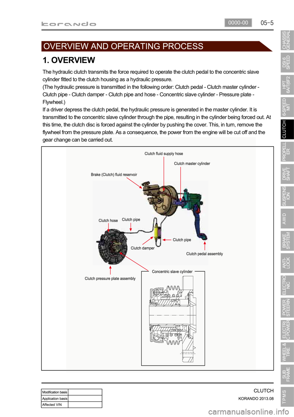
1. OVERVIEW
The hydraulic clutch transmits the force required to operate the clutch pedal to the concentric slave
cylinder fitted to the clutch housing as a hydraulic pressure.
(The hydraulic pressure is transmitted in the following order: Clutch pedal - Clutch master cylinder -
Clutch pipe - Clutch damper - Clutch pipe and hose - Concentric slave cylinder - Pressure plate -
Flywheel.)
If a driver depress the clutch pedal, the hydraulic pressure is generated in the master cylinder. It is
transmitted to the concentric slave cylinder through the pipe, resulting in the cylinder being forced out. At
this time, the clutch disc is forced against the cylinder by pushing the cover. This, in turn, remove the
flywheel from the pressure plate. As a consequence, the power from the engine will be cut off and the
gear change can be carried out.