drain bolt SSANGYONG KORANDO 2013 Service Manual
[x] Cancel search | Manufacturer: SSANGYONG, Model Year: 2013, Model line: KORANDO, Model: SSANGYONG KORANDO 2013Pages: 1336, PDF Size: 92.18 MB
Page 190 of 1336
0000-00
5) Guidelines on Engine Service
(1) Cautions before service works
Make sure to disconnect the negative (-) cable from the battery to prevent any damage to electric
systems.
Make sure to clean the working area and to prepare the necessary tools before service works.
Always place the ignition switch to OFF position if not required. Otherwise, there could be
unexpected damage to electric devices or personal injuries due to short-circuit.
To prevent the foreign material from entering into the fuel injection system, completely seal the inlets
of HP pump, fuel hoses and high pressure pipes.
To remoev the engine, use the dedicated equipments such as engine jack, transmission jack, engine
stand and engine crane. -
-
-
-
-
(2) Engine and accessories
When disassembling the engine, related parts (bolts, gaskets, etc.) should be stored as a set.
Clean the components completely with engine oil before assembling if needed.
Fully drain the engine oil, coolant and fuel from the vehicle and seal the inlets with the plugs before
removing the engine.
All the interference should be eliminated before removing the engine. -
-
-
-
(3) Electric devices
To prevent any damage to electric systems, make sure to disconnect the negative (-) cable from the
battery and place the ignition switch to OFF position before servicing.
Use only the specified parts with same ratings when replacing the electric devices. Check the
grounds and connections for looseness. -
- To prevent the personal injuries and vehicle damages that can be caused by mistakes during service
and to provide the optimized performance and safety after service works, the service technicials must
keep the basic cautions and service guidelines below. These could be easily forgotten during service
works.
Engine has a lot of precise components. The specified tightening torque and correct procedures should
be kept during service works. And, the working area is always clean and well prepared.
Extraordinary care should be taken when servicing the electric systems. Currently, the engine uses a lot
of electric devices. Short circuit and poor contact may cause the low engine performance, incomplete
combustion and other abnormalities.
Page 273 of 1336
0000-00
2) Inspection of Turbocharger
On-board Inspection 1.
Check the bolts and nuts foe looseness or missing
Check the intake and exhaust manifold for looseness or damage
Check the oil supply pipe and drain pipe for damages
Check the housing for crack and deterioration -
-
-
-
Inspection of turbine 2.
Remove the exhaust pipe at the opening of the turbine and check, with a lamp, the existence of
interference of housing and wheel, oil leakage and contamination (at blade edge) of foreign
materials.
Interference: In case where the oil leak sign exists, even the small traces of interferences on the
turbine wheel mean, most of times, that abrasion has occurred on the journal bearing. Must
inspect after overhauling the turbocharger.
Oil Leakage: Followings are the reasons for oil leakage condition -
-
Problems in engine: In case where the oil is smeared on inner wall section of the exhaust gas
opening.
Problems in turbocharger: In case where the oil is smeared on only at the exhaust gas
outlet section. *
* When problem occurs with the turbocharger, it could cause engine power decline,
excessive discharge of exhaust gas, outbreak of abnormal noise and excessive
consumption of oil.
Idling for long period of time can cause oil leakage to the turbine side due to low pressure of
exhaust gas and the rotation speed of turbine wheel. Please note this is not a turbocharger
problem.
Oil Drain Pipe Defect
In case where oil flow from the turbocharger sensor housing to the crank case is not smooth would
become the reason for leakage as oil builds up within the center housing. Also, oil thickens (sludge)
at high temperature and becomes the indirect reason of wheel hub section. In such case, clogging
and damage of the oil drain pipe and the pressure of blow-by gas within the crank case must be
inspected.
Damages due to Foreign Materials
When the foreign materials get into the system, it could induce inner damage as rotating balance of
the turbocharger gets out of alignment. -
-
Page 279 of 1336
0000-00
3. TROUBLESHOOTING
The followings are cautions to take in handling defects of turbocharger, which must be fully aware of.
1) Cautions
After stopping the engine, check whether the bolts on pipe connecting section are
loose as well as the connecting condition of vacuum port and modulator, which is
connected to the actuator.
During idling of the engine, check for leakage in the connecting section of pipe (hoses
and pipes, duct connections, after the turbocharger) by applying soap water. The
leakage condition in the engine block and turbine housing opening can be determined
by the occurrence of abnormal noise of exhaust.
By running the engine at idle speed, abnormal vibration and noise can be checked.
Immediately stop the engine when abnormal vibration and noise is detected and make
thorough inspection whether the turbocharger shaft wheel has any damages as well as
checking the condition of connections between pipes.
In case where the noise of engine is louder than usual, there is possibility of dampness
in the areas related with air cleaner and engine or engine block and turbocharger. And
it could affect the smooth supply of engine oil and discharge.
Check for damp condition in exhaust gas when there is sign of thermal discoloration or
discharge of carbon in connecting area of the duct.
When the engine rotates or in case where there is change in noise level, check for
clogging of air cleaner or air cleaner duct or if there is any significant amount of dust in
the compressor housing.
During the inspection of center housing, inspect inside of the housing by removing the
oil drain pipe to check for sludge generation and its attachment condition at shaft area
or turbine side.
Inspect or replace the air cleaner when the compressor wheel is damaged by inflow of
foreign materials.
Inspect both side of the turbocharger wheel after removing inlet and outlet pipe of the
turbocharger.
- Is the rotation smooth when the rotor is rotated by hand?
- Is the movement of bearing normal?
- Inspect whether there has been any signs of interference between two wheels. 1.
2.
3.
4.
5.
6.
7.
8.
9.
It's important not to drive the engine when the intake manifold hose has been removed.
Page 428 of 1336
0000-00
5) Guidelines on Engine Service
(1) Cautions before service works
Make sure to disconnect the negative (-) cable from the battery to prevent any damage to electric
systems.
Make sure to clean the working area and to prepare the necessary tools before service works.
Always place the ignition switch to OFF position if not required. Otherwise, there could be unexpected
damage to electric devices or personal injuries due to short-circuit.
To prevent the foreign material from entering into the fuel injection system, completely seal the inlets o
f
HP pump, fuel hoses and high pressure pipes.
To remoev the engine, use the dedicated equipments such as engine jack, transmission jack, engine
stand and engine crane. -
-
-
-
-
(2) Engine and accessories
When disassembling the engine, related parts (bolts, gaskets, etc.) should be stored as a set.
Clean the components completely with engine oil before assembling if needed.
Fully drain the engine oil, coolant and fuel from the vehicle and seal the inlets with the plugs before
removing the engine.
All the interference should be eliminated before removing the engine. -
-
-
- To prevent the personal injuries and vehicle damages that can be caused by mistakes during service
and to provide the optimized performance and safety after service works, the service technicials must
keep the basic cautions and service guidelines below. These could be easily forgotten during service
works.
Engine has a lot of precise components. The specified tightening torque and correct procedures should
be kept during service works. And, the working area is always clean and well prepared.
To prevent any damage to electric systems, make sure to disconnect the negative (-) cable from the
battery and place the ignition switch to OFF position before servicing.
Use only the specified parts with same ratings when replacing the electric devices. Check the
grounds and connections for looseness. -
-
(3) Electric devices
Extraordinary care should be taken when servicing the electric systems. Currently, the engine uses a lot
of electric devices. Short circuit and poor contact may cause the low engine performance, incomplete
combustion and other abnormalities.
When working with the fuel or oil systems in enclosed area, always keep the working area well-
ventilated and never allow anybody to smoke.
Gaskets and seals on the fuel and oil systems should be replaced with new ones. All bolts and nuts
should be tightened as specified.
Make sure to check the connections for leak after installation. -
-
-
(4) Fuel and lubrication system
Page 437 of 1336
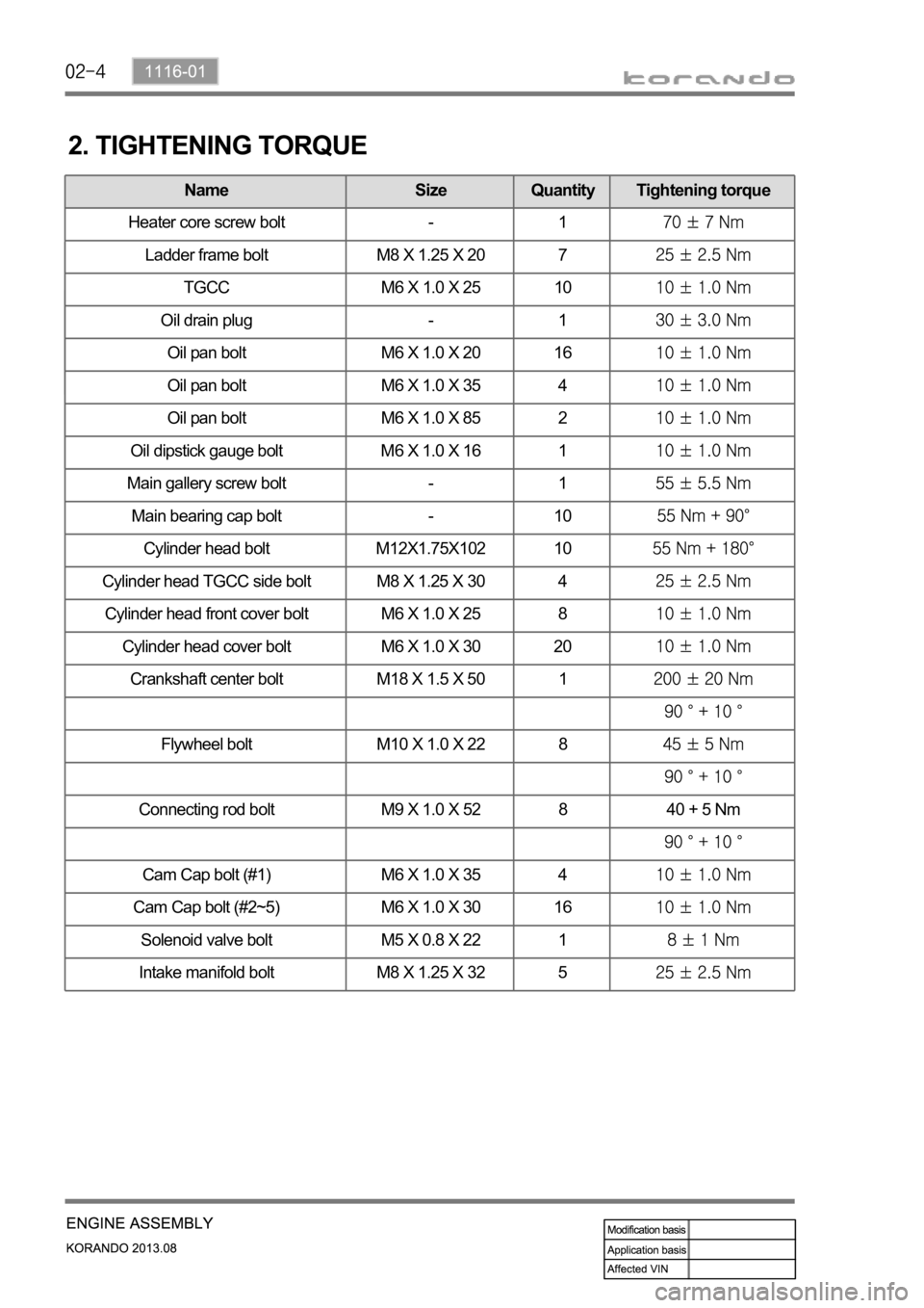
Name Size Quantity Tightening torque
Oil pan bolt M6 X 1.0 X 20 16
Oil pan bolt M6 X 1.0 X 35 4
Oil pan bolt M6 X 1.0 X 85 2
Oil dipstick gauge bolt M6 X 1.0 X 16 1
Camshaft cap M6 X 1.0 X 30 20
Main gallery screw bolt - 1
Main bearing cap bolt - 10
Cylinder head bolt M12X1.75X102 10
Cylinder head TGCC side bolt M8 X 1.25 X 30 4
Cylinder head front cover bolt M6 X 1.0 X 25 8
Cylinder head cover bolt M6 X 1.0 X 30 20
Crankshaft center bolt M18 X 1.5 X 50 1
Flywheel bolt M10 X 1.0 X 22 8
Connecting rod bolt M9 X 1.0 X 52 8 40 + 5 Nm
Cam Cap bolt (#1) M6 X 1.0 X 35 4
Cam Cap bolt (#2~5) M6 X 1.0 X 30 16
Solenoid valve bolt M5 X 0.8 X 22 1
Intake manifold bolt M8 X 1.25 X 32 5
2. TIGHTENING TORQUE
Name Size Quantity Tightening torque
Heater core screw bolt - 1
Ladder frame bolt M8 X 1.25 X 20 7
TGCC M6 X 1.0 X 25 10
Oil drain plug - 1
Oil pan bolt M6 X 1.0 X 20 16
Oil pan bolt M6 X 1.0 X 35 4
Oil pan bolt M6 X 1.0 X 85 2
Oil dipstick gauge bolt M6 X 1.0 X 16 1
Page 440 of 1336
1116-01
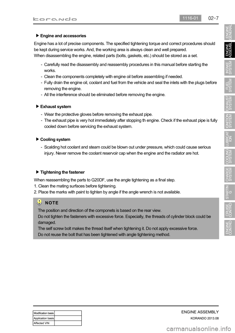
Engine and accessories
Engine has a lot of precise components. The specified tightening torque and correct procedures should
be kept during service works. And, the working area is always clean and well prepared.
When disassembling the engine, related parts (bolts, gaskets, etc.) should be stored as a set.
Carefully read the disassembly and reassembly procedures in this manual before starting the
works.
Clean the components completely with engine oil before assembling if needed.
Fully drain the engine oil, coolant and fuel from the vehicle and seal the inlets with the plugs before
removing the engine.
All the interference should be eliminated before removing the engine. -
-
-
-
Tightening the fastener
When reassembling the parts to G20DF, use the angle tightening as a final step.
1. Clean the mating surfaces before tightening.
2. Place the marks with paint to tighten by angle if the angle wrench is not available. Exhaust system
Wear the protective gloves before removing the exhaust pipe.
The exhaust pipe is very hot immediately after stopping th engine. Check if the exhaust pipe is fully
cooled down before servicing the exhaust system. -
-
Cooling system
Scalding hot coolant and steam could be blown out under pressure, which could cause serious
injury. Never remove the coolant reservoir cap when the engine and the radiator are hot. -
The position and direction of the componets is based on the rear view.
Do not tighten the fasteners with excessive force. Especially, the threads of cylinder block could be
damaged.
The self screw bolt makes the thread itself when tightening it. Do not apply excessive force.
Do not reuse the bolt that has been tightened with angle tightening method.
Page 509 of 1336
1535-01
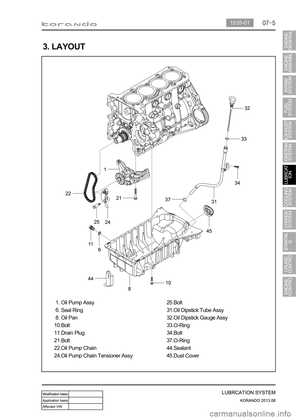
3. LAYOUT
Oil Pump Assy
Seal Ring
Oil Pan
Bolt
Drain Plug
Bolt
Oil Pump Chain
Oil Pump Chain Tensioner Assy 1.
6.
8.
10.
11.
21.
22.
24.Bolt
Oil Dipstick Tube Assy
Oil Dipstick Gauge Assy
O-Ring
Bolt
O-Ring
Sealant
Dust Cover 25.
31.
32.
33.
34.
37.
44.
45.
Page 510 of 1336
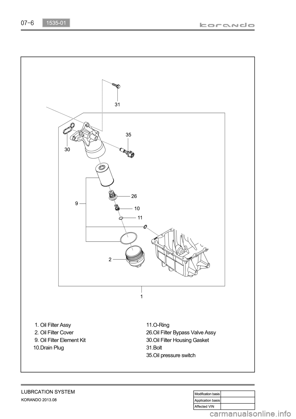
Oil Filter Assy
Oil Filter Cover
Oil Filter Element Kit
Drain Plug 1.
2.
9.
10.O-Ring
Oil Filter Bypass Valve Assy
Oil Filter Housing Gasket
Bolt
Oil pressure switch 11.
26.
30.
31.
35.
Page 1007 of 1336
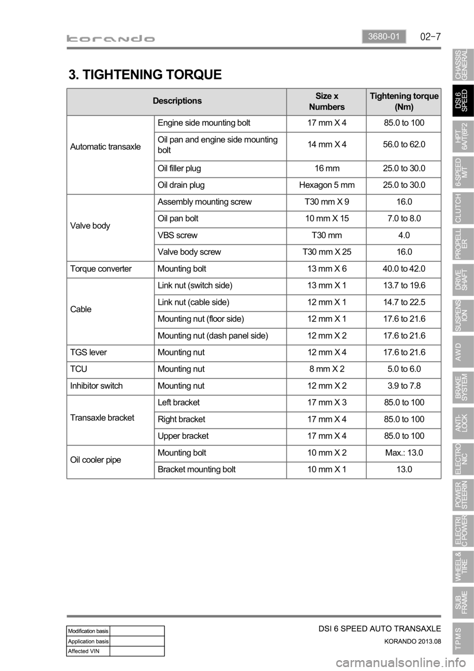
3680-01
3. TIGHTENING TORQUE
DescriptionsSize x
NumbersTightening torque
(Nm)
Automatic transaxleEngine side mounting bolt 17 mm X 4 85.0 to 100
Oil pan and engine side mounting
bolt14 mm X 4 56.0 to 62.0
Oil filler plug 16 mm 25.0 to 30.0
Oil drain plug Hexagon 5 mm 25.0 to 30.0
Valve bodyAssembly mounting screw T30 mm X 9 16.0
Oil pan bolt 10 mm X 15 7.0 to 8.0
VBS screw T30 mm 4.0
Valve body screw T30 mm X 25 16.0
Torque converter Mounting bolt 13 mm X 6 40.0 to 42.0
CableLink nut (switch side) 13 mm X 1 13.7 to 19.6
Link nut (cable side) 12 mm X 1 14.7 to 22.5
Mounting nut (floor side) 12 mm X 1 17.6 to 21.6
Mounting nut (dash panel side) 12 mm X 2 17.6 to 21.6
TGS lever Mounting nut 12 mm X 4 17.6 to 21.6
TCU Mounting nut 8 mm X 2 5.0 to 6.0
Inhibitor switch Mounting nut 12 mm X 2 3.9 to 7.8
Transaxle bracketLeft bracket 17 mm X 3 85.0 to 100
Right bracket 17 mm X 4 85.0 to 100
Upper bracket 17 mm X 4 85.0 to 100
Oil cooler pipeMounting bolt 10 mm X 2 Max.: 13.0
Bracket mounting bolt 10 mm X 1 13.0
Page 1034 of 1336
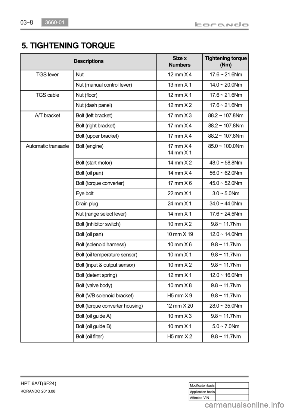
Automatic transaxle Bolt (engine) 17 mm X 4
14 mm X 1 85.0 ~ 100.0Nm
Bolt (start motor) 14 mm X 2 48.0 ~ 58.8Nm
Bolt (oil pan) 14 mm X 4 56.0 ~ 62.0Nm
Bolt (torque converter) 17 mm X 6 45.0 ~ 52.0Nm
Eye bolt 22 mm X 1 3.0 ~ 5.0Nm
Drain plug 24 mm X 1 34.0 ~ 44.0Nm
Nut (range select lever) 14 mm X 1 17.6 ~ 24.5Nm
Bolt (inhibitor switch) 10 mm X 2 9.8 ~ 11.7Nm
Bolt (oil pan) 10 mm X 19 12.0 ~ 14.0Nm
Bolt (solenoid harness) 10 mm X 6 9.8 ~ 11.7Nm
Bolt (oil temperature sensor) 10 mm X 1 9.8 ~ 11.7Nm
Bolt (input & output sensor) 10 mm X 2 9.8 ~ 11.7Nm
Bolt (detent spring) 12 mm X 1 12.0 ~ 16.0Nm
Bolt (valve body) 10 mm X 8 9.8 ~ 11.7Nm
Bolt (V/B solenoid bracket) H5 mm X 9 9.8 ~ 11.7Nm
Bolt (torque converter housing) 12 mm X 20 28.0 ~ 35.0Nm
Bolt (oil guide A) 10 mm X 3 9.8 ~ 11.7Nm
Bolt (oil guide B) 10 mm X 1 5.0 ~ 7.0Nm
Bolt (oil filter) H5 mm X 2 9.8 ~ 11.7Nm
5. TIGHTENING TORQUE
DescriptionsSize x
NumbersTightening torque
(Nm)
TGS lever Nut 12 mm X 4 17.6 ~ 21.6Nm
Nut (manual control lever) 13 mm X 1 14.0 ~ 20.0Nm
Nut (floor) 12 mm X 1 17.6 ~ 21.6Nm
Nut (dash panel) 12 mm X 2 17.6 ~ 21.6Nm
A/T bracket Bolt (left bracket) 17 mm X 3 88.2 ~ 107.8Nm
Bolt (right bracket) 17 mm X 4 88.2 ~ 107.8Nm
Bolt (upper bracket) 17 mm X 4 88.2 ~ 107.8Nm
TGS lever
TGS cable