differential SSANGYONG KORANDO 2013 Service Manual
[x] Cancel search | Manufacturer: SSANGYONG, Model Year: 2013, Model line: KORANDO, Model: SSANGYONG KORANDO 2013Pages: 1336, PDF Size: 92.18 MB
Page 207 of 1336

0000-00
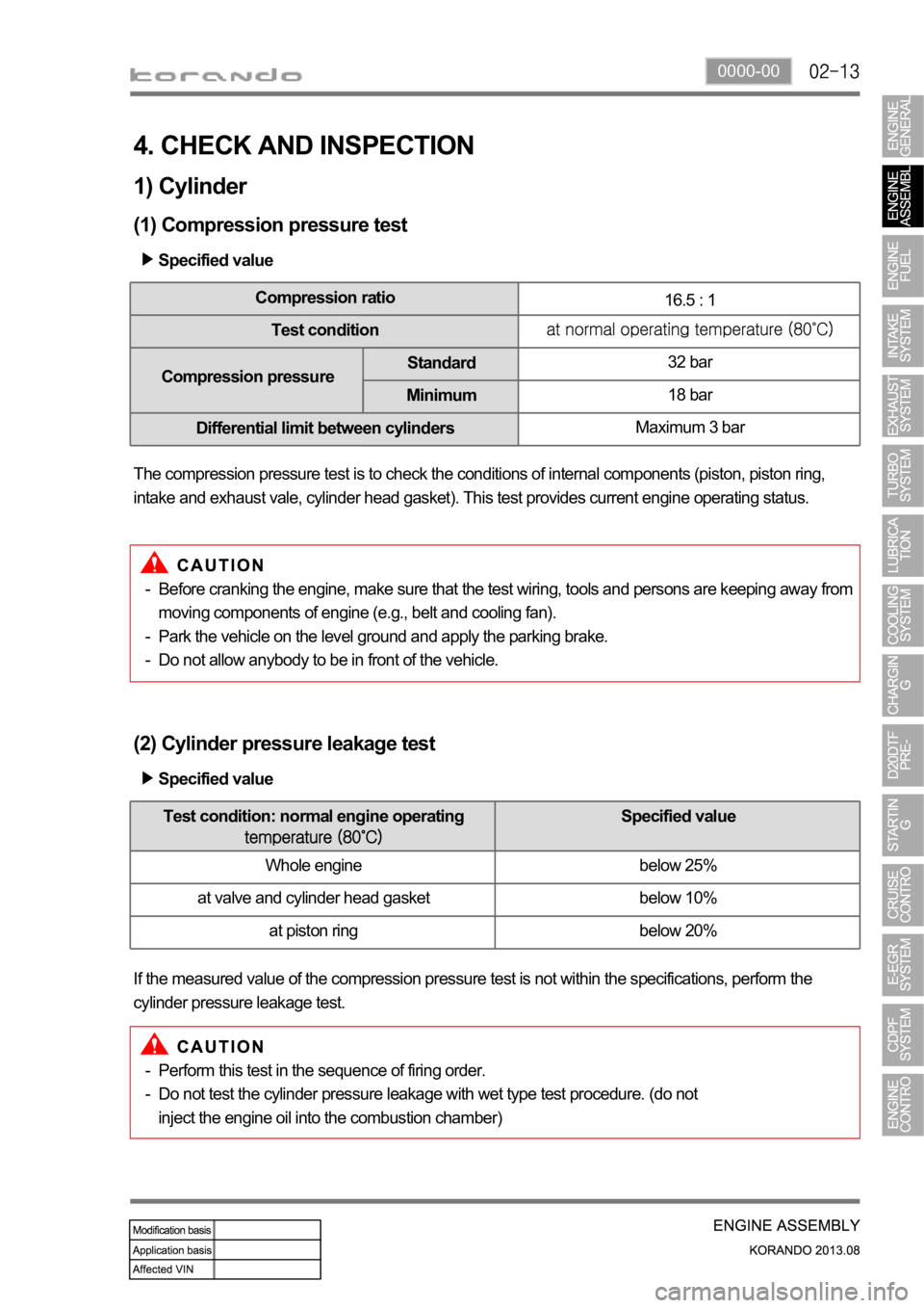
4. CHECK AND INSPECTION
1) Cylinder
(1) Compression pressure test
Specified value
Compression ratio
16.5 : 1
Test condition
Compression pressureStandard32 bar
Minimum18 bar
Differential limit between cylindersMaximum 3 bar
The compression pressure test is to check the conditions of internal components (piston, piston ring,
intake and exhaust vale, cylinder head gasket). This test provides current engine operating status.
Before cranking the engine, make sure that the test wiring, tools and persons are keeping away from
moving components of engine (e.g., belt and cooling fan).
Park the vehicle on the level ground and apply the parking brake.
Do not allow anybody to be in front of the vehicle. -
-
-
(2) Cylinder pressure leakage test
If the measured value of the compression pressure test is not within the specifications, perform the
cylinder pressure leakage test.Specified value
Perform this test in the sequence of firing order.
Do not test the cylinder pressure leakage with wet type test procedure. (do not
inject the engine oil into the combustion chamber) -
-
Test condition: normal engine operating Specified value
Whole engine below 25%
at valve and cylinder head gasket below 10%
at piston ring below 20%
Page 362 of 1336

Excessive overload of CDPF (warning lamp illuminated)
If the vehicle is driven at a speed of 5 to 10
km/h for an extended period of time, the soot
accumulated in the CDPF cannot be burned
as the CDPF cannot reach the regeneration
temperature. Then, an excessive amount of
soot can be accumulated in the CDPF.
This case is much worse than the simple over-
load of the CDPF. To inform this to the driver,
the engine warning lamp comes on and the
engine power is decreased to protect the
system.
To solve this problem, blow soot between the
engine and exhaust system several times and
erase the related DTC. Then, check if the
same DTC is regenerated again. If so, check
the DTC related to the differential pressure
sensor. 1.
2.
3.
Page 364 of 1336

Engine ECU (D20DTF)
Post-injectionDifferential pressure sensor
Calculates the amount of PM
collected by reading the pressure
difference between before and
after the CDPF.Electric throttle body
Regulates the rate of air
intake.
CDPF
(DOC + DPF)Front temperature
sensor
Protects the
turbocharger.Rear temperature
sensor
Measures the
temperature of fuel
combustion.
2. COMPONENT
Oxygen
sensor
Page 365 of 1336

1114-00
3. INPUT/OUTPUT DEVICES
Front temperature sensor: This sensor is installed at the inlet of DOC and detects whether the DOC
can burn (oxidize) the post-injected fuel or not.
Rear temperature sensor: This sensor is installed at the inlet of DPF and monitors that the 1.
2.
post-injection is decreased.
amount of fuel post-injection is increased. -
-
Differential pressure sensor: This sensor checks the amount of PM collected by calculating the
pressure difference between before and after the CDPF.
Electric throttle valve: This valve reduces the intake air flow to raise the temperature of the exhaust
gas when the CDPF is operating during idling. 3.
4.
Page 366 of 1336

A DPS (Differential Pressure Sensor) measures the pressure difference between before and after the
CDPF and detects whether the soot is collected in the CDPF or not. If PM is collected in the CDPF (In
this case the pressure difference between before and after the CDPF exceeds the specified value.
Normally, the system sends the signal when the driving distance becomes approx. 600 to 1,200 km), the
temperature of exhaust gas is increased and the post-injection is started for regeneration. The amount of
fuel post-injection is controlled by the exhaust gas temperature measured by the rear temperature
increase the regeneration temperature. Otherwise, the fuel injection amount is decreased or the fuel is
not injected.
When the engine is running with low load, the intake air amount is also controlled as well as fuel injection
amount. This function is used to increaser the combustion temperature by increasing the amount of fuel
post-injection with the lowest air amount within the specified control logic.
4. POST-INJECTION AND AIR MASS CONTROL
Page 367 of 1336

1114-00
ECU (DCM 3.7)
T-MAP sensorIntake air
volume
Detecting
excess of PM
amount limit
Boos
t
pressure
/
temperature
Front EGT sensor
Measures the temperature of
DOC.
The DOC performs the redox
reaction at between 300 and
sensor monitors the
temperature of DOC.
Differential pressure sensor
Measures the pressure values
of before and after the CDPF.
The pressure difference
between before and after the
CDPF is measured by the
differential pressure sensor (If
PM is collected in the CDPF,
the pressure difference
between before and after the
CDPF exceeds the specified
value).
Rear EGT sensor
Measures the temperature of
DPF.
The DPF burns the soot with
hot exhaust gases
(regeneration) at around
sensor monitors the
temperature of DPF.
Injector (C3I)
Controls the post-injection.
Electric throttle body
Controls the intake air
volume.
HFM sensor
Page 368 of 1336

Collecting PM
The engine ECU detects the
amount of PM collected by the
information from the
temperature sensors and
differential pressure sensor.
When the soot is accumulated,
the engine ECU performs post-
injection to increase the
exhaust gas temperature and
burns the collected PM at
Oxidation (DOC)
When the exhaust gas enters
into the CDPF assembly, its
CO, HC and PM are reduced
by the redox reaction of the
DOC. The remaining PM is
filtered and collected in CDPF,
and the temperature of the
exhaust gas is increased to
5. OPERATING PROCESS
[Configuration and principle of operation]
The exhaust gas
passed through the
exhaust manifold
enters into the CDPF
assembly (at approx
Page 372 of 1336
![SSANGYONG KORANDO 2013 Service Manual No. Sensor item Data Unit Description
1 Driven distance from last
CDPF regeneration0 km
2 CDPF regeneration history
(distance/time) Index0 -
3 Driven distance between
CDPF regenerations[0]0 SSANGYONG KORANDO 2013 Service Manual No. Sensor item Data Unit Description
1 Driven distance from last
CDPF regeneration0 km
2 CDPF regeneration history
(distance/time) Index0 -
3 Driven distance between
CDPF regenerations[0]0](/img/67/57503/w960_57503-371.png)
No. Sensor item Data Unit Description
1 Driven distance from last
CDPF regeneration0 km
2 CDPF regeneration history
(distance/time) Index0 -
3 Driven distance between
CDPF regenerations[0]0 km
4 Driven distance between
CDPF regenerations[1]0 km
5 Driven distance between
CDPF regenerations[2]0 km
6 Driven distance between
CDPF regenerations[3]0 km
7 Driven distance between
CDPF regenerations[4]0 km
8 CDPF regeneration time[0] 0.0 S
9 CDPF regeneration time[2] 0.0 S
10 CDPF regeneration time[2] 0.0 S
11 CDPF regeneration time[3] 0.0 S
12 CDPF regeneration time[4] 0.0 S
13 CDPF regeneration history
(OK/Fail) Index0 -
14 CDPF regeneration history[0] OK OK/Fail
15 CDPF regeneration history[1] OK OK/Fail
16 CDPF regeneration history[2] OK OK/Fail
17 CDPF regeneration history[3] OK OK/Fail
18 CDPF regeneration history[4] OK OK/Fail
19 Times of CDPF regeneration
start (differential pressure)0 -
Driven distance from last generation up to
now
Display regeneration history (distance/time)
stored until now in figure, Index ([0] ~ [4])
The regeneration distance/time is stored up
to the last 5 events in sequence and the
oldest one will be deleted if the number of
events is exceeded 5 times.
The currently displayed index value indicates
where the regeneration information will be
stored in the future and the just previous
value shows the last regeneration
information.
Ex) Index value: 3 (last regeneration
information stored at 2)
Display regeneration history (OK/Fail) stored
until now in figure, Index ([0]~[4])
The regeneration distance/time is stored up
to the last 5 events in sequence and the
oldest one will be deleted if the number of
events is exceeded 5 times.
The currently displayed index value indicates
where the regeneration information will be
stored in the future and the just previous
value shows the last regeneration
information.
Ex) Index value: 3 (last regeneration
information stored at 2)
Times which regeneration is requested using
differential pressure sensor signal
9. DESCRIPTION ON CDPF REGENERATION
Page 376 of 1336

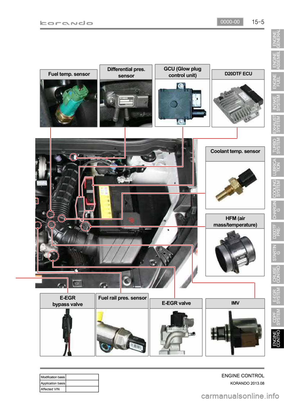
0000-00
Coolant temp. sensor
HFM (air
mass/temperature)
Fuel temp. sensorDifferential pres.
sensorD20DTF ECU
IMV
E-EGR
bypass valve
E-EGR valve
Fuel rail pres. sensor
GCU (Glow plug
control unit)
Page 378 of 1336

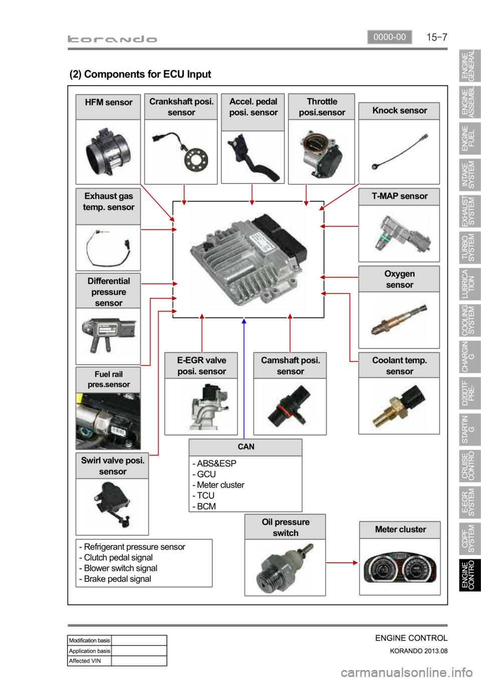
0000-00
Oil pressure
switch
Fuel rail
pres.sensor
Differential
pressure
sensor
Swirl valve posi.
sensor
Meter cluster
Coolant temp.
sensorE-EGR valve
posi. sensor
Oxygen
sensor
Exhaust gas
temp. sensor
HFM sensor
(2) Components for ECU Input
Crankshaft posi.
sensorAccel. pedal
posi. sensorThrottle
posi.sensor
Knock sensor
T-MAP sensor
Camshaft posi.
sensor
CAN
- ABS&ESP
- GCU
- Meter cluster
- TCU
- BCM
- Refrigerant pressure sensor
- Clutch pedal signal
- Blower switch signal
- Brake pedal signal