headlamp SSANGYONG KORANDO 2013 Service Manual
[x] Cancel search | Manufacturer: SSANGYONG, Model Year: 2013, Model line: KORANDO, Model: SSANGYONG KORANDO 2013Pages: 1336, PDF Size: 92.18 MB
Page 308 of 1336
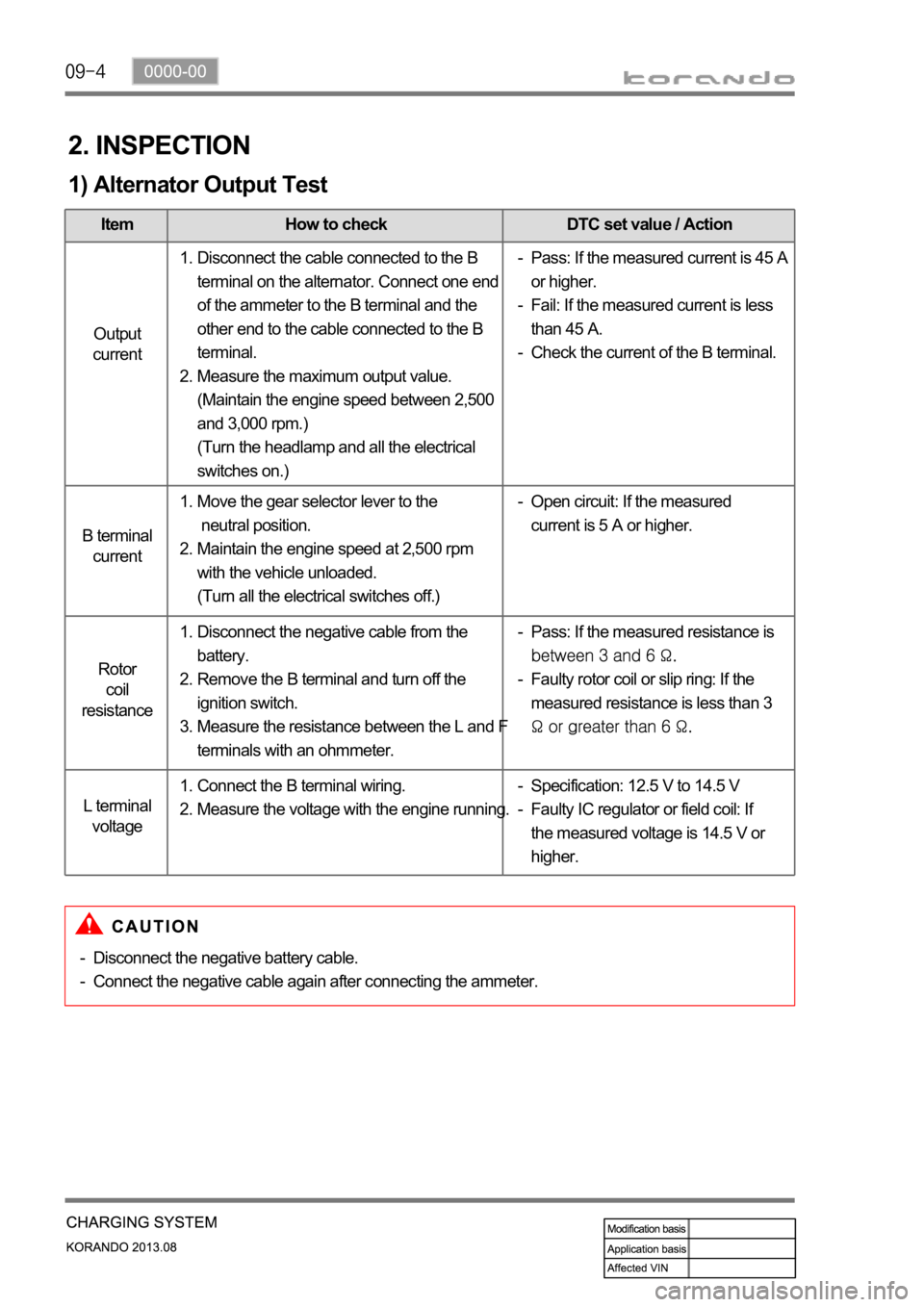
2. INSPECTION
1) Alternator Output Test
Item How to check DTC set value / Action
Output
current
B terminal
current
Rotor
coil
resistance
L terminal
voltage
Disconnect the cable connected to the B
terminal on the alternator. Connect one end
of the ammeter to the B terminal and the
other end to the cable connected to the B
terminal.
Measure the maximum output value.
(Maintain the engine speed between 2,500
and 3,000 rpm.)
(Turn the headlamp and all the electrical
switches on.) 1.
2.Pass: If the measured current is 45 A
or higher.
Fail: If the measured current is less
than 45 A.
Check the current of the B terminal. -
-
-
Move the gear selector lever to the
neutral position.
Maintain the engine speed at 2,500 rpm
with the vehicle unloaded.
(Turn all the electrical switches off.) 1.
2.Open circuit: If the measured
current is 5 A or higher. -
Disconnect the negative cable from the
battery.
Remove the B terminal and turn off the
ignition switch.
Measure the resistance between the L and F
terminals with an ohmmeter. 1.
2.
3.Pass: If the measured resistance is
Faulty rotor coil or slip ring: If the
measured resistance is less than 3
-
-
Connect the B terminal wiring.
Measure the voltage with the engine running. 1.
2.Specification: 12.5 V to 14.5 V
Faulty IC regulator or field coil: If
the measured voltage is 14.5 V or
higher. -
-
Disconnect the negative battery cable.
Connect the negative cable again after connecting the ammeter. -
-
Page 529 of 1336
Item How to check DTC set value / Action
Output current
B terminal current
Rotor coil
resistance
L terminal voltage
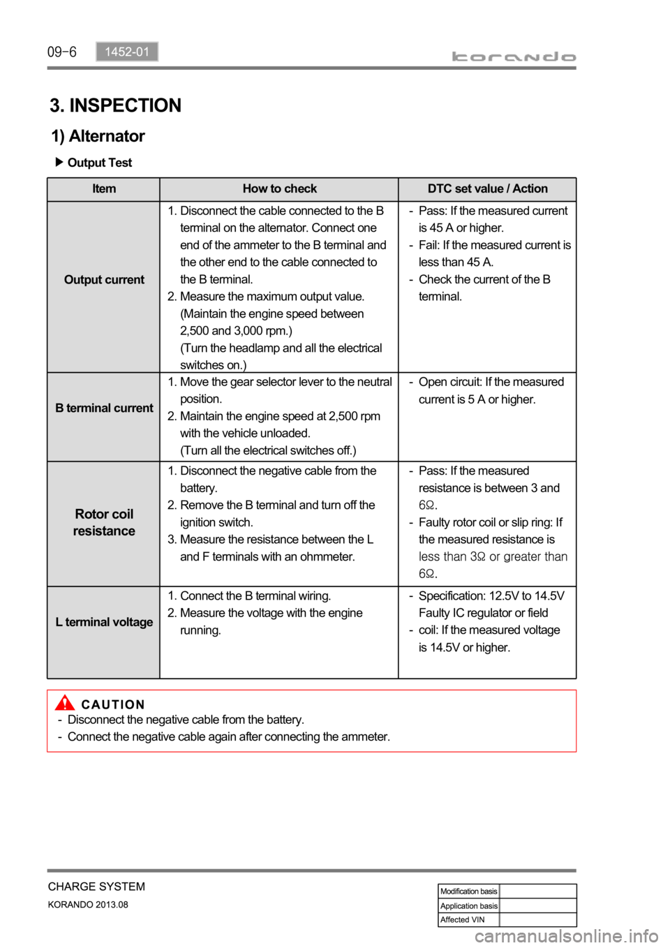
3. INSPECTION
1) Alternator
Output Test
Disconnect the cable connected to the B
terminal on the alternator. Connect one
end of the ammeter to the B terminal and
the other end to the cable connected to
the B terminal.
Measure the maximum output value.
(Maintain the engine speed between
2,500 and 3,000 rpm.)
(Turn the headlamp and all the electrical
switches on.) 1.
2.Pass: If the measured current
is 45 A or higher.
Fail: If the measured current is
less than 45 A.
Check the current of the B
terminal. -
-
-
Move the gear selector lever to the neutral
position.
Maintain the engine speed at 2,500 rpm
with the vehicle unloaded.
(Turn all the electrical switches off.) 1.
2.Open circuit: If the measured
current is 5 A or higher. -
Disconnect the negative cable from the
battery.
Remove the B terminal and turn off the
ignition switch.
Measure the resistance between the L
and F terminals with an ohmmeter. 1.
2.
3.Pass: If the measured
resistance is between 3 and
Faulty rotor coil or slip ring: If
the measured resistance is
-
-
Connect the B terminal wiring.
Measure the voltage with the engine
running. 1.
2.
Specification: 12.5V to 14.5V
Faulty IC regulator or field
coil: If the measured voltage
is 14.5V or higher. -
-
Disconnect the negative cable from the battery.
Connect the negative cable again after connecting the ammeter. -
-
Page 603 of 1336
0000-00
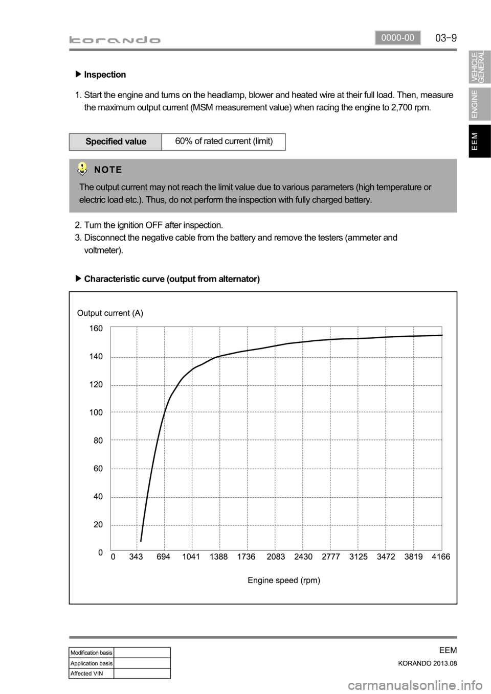
Inspection
Start the engine and turns on the headlamp, blower and heated wire at their full load. Then, measure
the maximum output current (MSM measurement value) when racing the engine to 2,700 rpm. 1.
Specified value60% of rated current (limit)
Turn the ignition OFF after inspection.
Disconnect the negative cable from the battery and remove the testers (ammeter and
voltmeter). 2.
3.
Characteristic curve (output from alternator)
The output current may not reach the limit value due to various parameters (high temperature or
electric load etc.). Thus, do not perform the inspection with fully charged battery.
Page 615 of 1336
0000-00
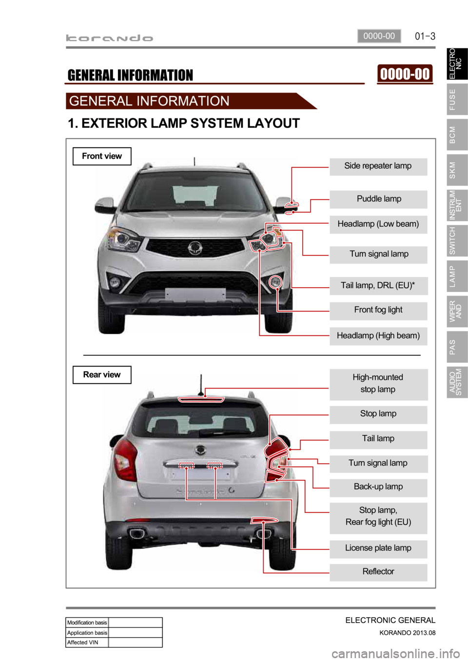
Turn signal lamp
Side repeater lamp
Puddle lamp
1. EXTERIOR LAMP SYSTEM LAYOUT
Headlamp (High beam)
Tail lamp, DRL (EU)*
Front fog light
Tail lamp
High-mounted
stop lamp
Stop lamp
License plate lamp
Turn signal lamp
Stop lamp,
Rear fog light (EU)
Reflector
Front view
Rear view
Headlamp (Low beam)
Back-up lamp
Page 616 of 1336
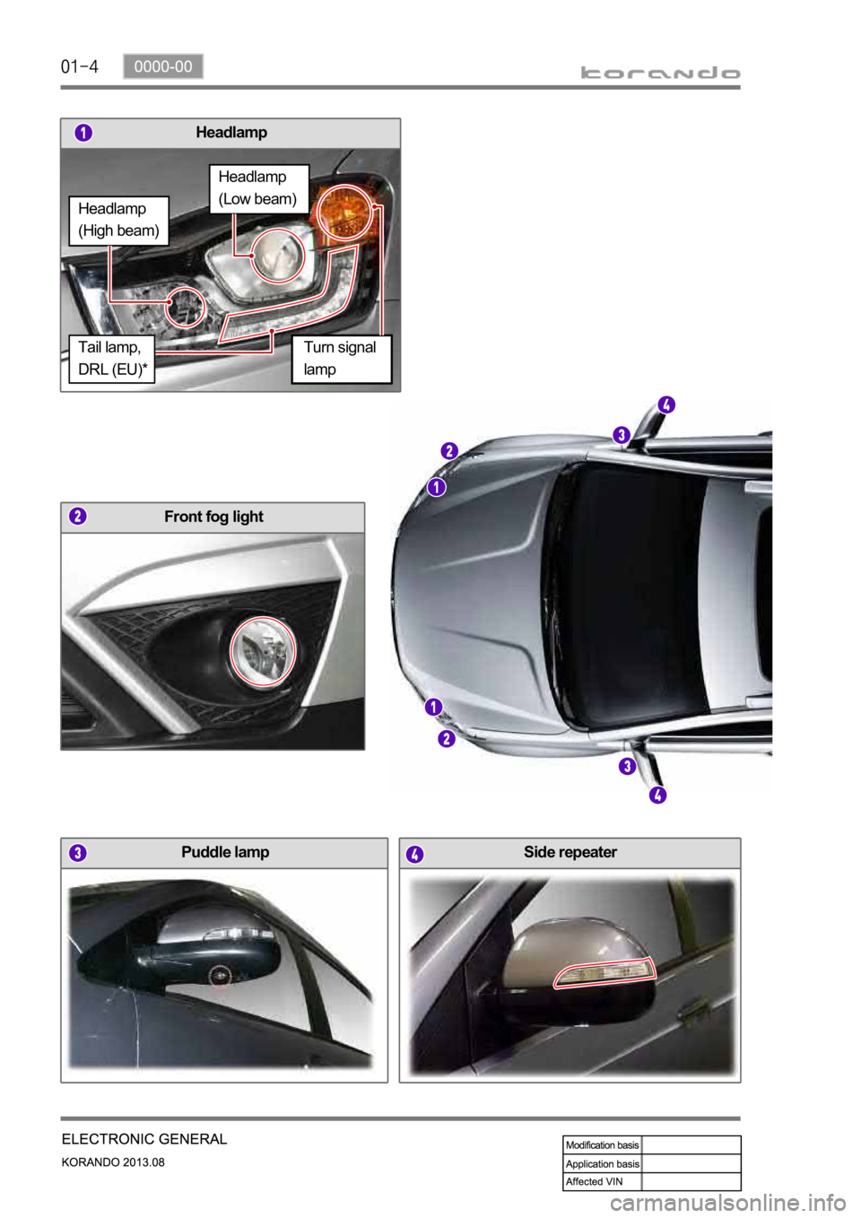
Headlamp
Puddle lamp
Front fog light
Side repeater
Turn signal
lamp
Headlamp
(High beam)
Headlamp
(Low beam)
Tail lamp,
DRL (EU)*
Page 632 of 1336
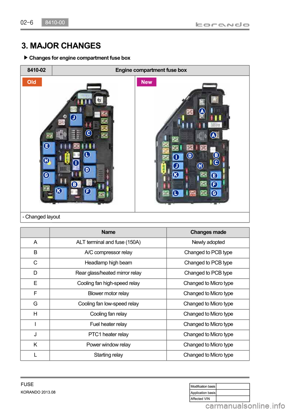
3. MAJOR CHANGES
Changes for engine compartment fuse box
8410-02 Engine compartment fuse box
- Changed layout
Name Changes made
A ALT terminal and fuse (150A) Newly adopted
B A/C compressor relay Changed to PCB type
C Headlamp high beam Changed to PCB type
D Rear glass/heated mirror relay Changed to PCB type
E Cooling fan high-speed relay Changed to Micro type
F Blower motor relay Changed to Micro type
G Cooling fan low-speed relay Changed to Micro type
H Cooling fan relay Changed to Micro type
I Fuel heater relay Changed to Micro type
J PTC1 heater relay Changed to Micro type
K Power window relay Changed to Micro type
L Starting relay Changed to Micro type
Page 636 of 1336
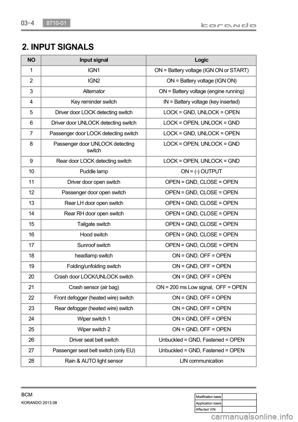
2. INPUT SIGNALS
NO Input signal Logic
1 IGN1 ON = Battery voltage (IGN ON or START)
2 IGN2 ON = Battery voltage (IGN ON)
3 Alternator ON = Battery voltage (engine running)
4 Key reminder switch IN = Battery voltage (key inserted)
5 Driver door LOCK detecting switch LOCK = GND, UNLOCK = OPEN
6 Driver door UNLOCK detecting switch LOCK = OPEN, UNLOCK = GND
7 Passenger door LOCK detecting switch LOCK = GND, UNLOCK = OPEN
8 Passenger door UNLOCK detecting
switchLOCK = OPEN, UNLOCK = GND
9 Rear door LOCK detecting switch LOCK = OPEN, UNLOCK = GND
10 Puddle lamp ON = (-) OUTPUT
11 Driver door open switch OPEN = GND, CLOSE = OPEN
12 Passenger door open switch OPEN = GND, CLOSE = OPEN
13 Rear LH door open switch OPEN = GND, CLOSE = OPEN
14 Rear RH door open switch OPEN = GND, CLOSE = OPEN
15 Tailgate switch OPEN = GND, CLOSE = OPEN
16 Hood switch OPEN = GND, CLOSE = OPEN
17 Sunroof switch OPEN = GND, CLOSE = OPEN
18 headlamp switch ON = GND, OFF = OPEN
19 Folding/unfolding switch ON = GND, OFF = OPEN
20 Crash door LOCK/UNLOCK switch ON = GND, OFF = OPEN
21 Crash sensor (air bag) ON = 200 ms Low signal, OFF = OPEN
22 Front defogger (heated wire) switch ON = GND, OFF = OPEN
23 Rear defogger (heated wire) switch ON = GND, OFF = OPEN
24 Wiper switch 1 ON = GND, OFF = OPEN
25 Wiper switch 2 ON = GND, OFF = OPEN
26 Driver seat belt switch Unbuckled = GND, Fastened = OPEN
27 Passenger seat belt switch (only EU) Unbuckled = GND, Fastened = OPEN
28 Rain & AUTO light sensor LIN communication
Page 703 of 1336
8710-01
REKES key switch description
Door LOCK (locks the doors and tailgate when pressed briefly) 1.
All doors and the tailgate are locked and the theft deterrent mode is activated.
When the theft deterrent mode is activated, the hazard warning lamp flashes twice. When this
button is pressed once more within 4 seconds, the hazard warning lamp flashes twice and the
buzzer sounds once. -
-
Panic (Press and hold for 2 seconds or more) 3.
If this button is pressed for 2 seconds or more, the hazard warning lamp flashes while the buzzer
sounds for approx. 30 seconds.
If the door LOCK button or panic button is pressed, this function is deactivated. -
- Door UNLOCK (unlocks the doors and tailgate when pressed briefly) 2.
If this button is pressed briefly, all doors and the tailgate are unlocked and the theft deterrent
mode is deactivated.
When the theft deterrent mode is deactivated, the hazard warning lamp flashes once.
In theft deterrent mode, if a door, tailgate or engine hood is not opened within 30 seconds after
the door is unlocked by a remote controller, the doors are locked with the hazard warning lamp
and buzzer activated (lamp flashes twice and buzzer sounds once, the theft deterrent mode is
activated again). -
-
-
13. REMOTE KEYLESS ENTRY SYSTEM (REKES)
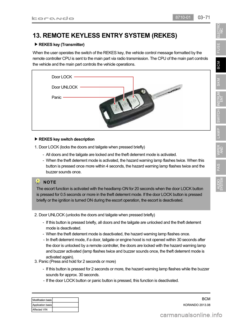
REKES key (Transmitter)
When the user operates the switch of the REKES key, the vehicle control message formatted by the
remote controller CPU is sent to the main part via radio transmission. The CPU of the main part controls
the vehicle and the main part controls the vehicle operations.
Door LOCK
Door UNLOCK
Panic
The escort function is activated with the headlamp ON for 20 seconds when the door LOCK button
is pressed for 0.5 seconds or more in the theft deterrent mode. If the door LOCK button is pressed
briefly or the ignition is turned ON during the escort operation, the escort is deactivated.
Page 747 of 1336
8710-01
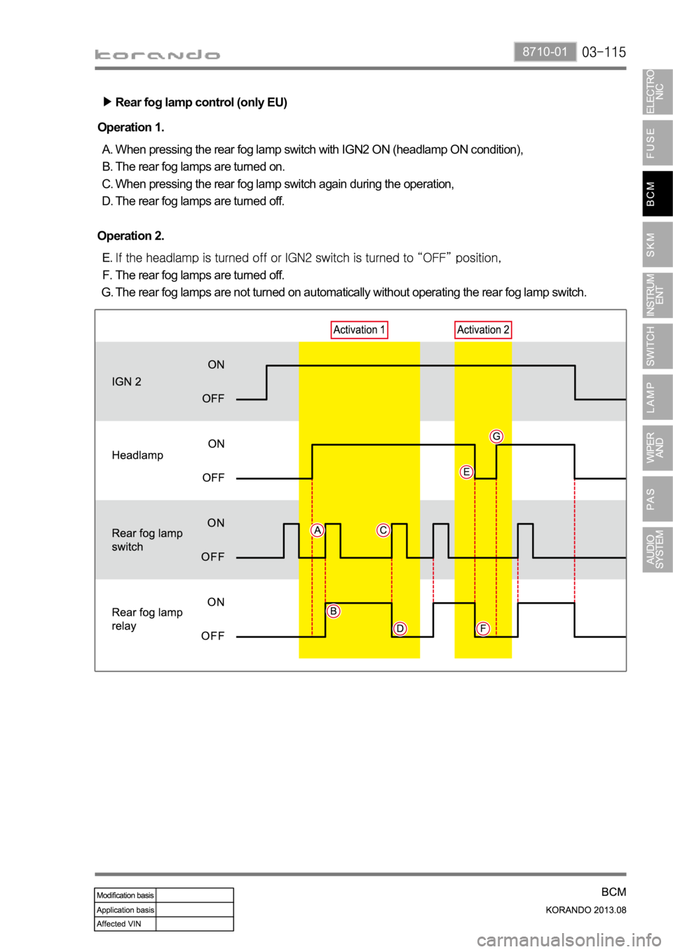
Rear fog lamp control (only EU)
When pressing the rear fog lamp switch with IGN2 ON (headlamp ON condition),
The rear fog lamps are turned on.
When pressing the rear fog lamp switch again during the operation,
The rear fog lamps are turned off. A.
B.
C.
D. Operation 1.
The rear fog lamps are turned off.
The rear fog lamps are not turned on automatically without operating the rear fog lamp switch. E.
F.
G. Operation 2.
Page 797 of 1336
8010-01
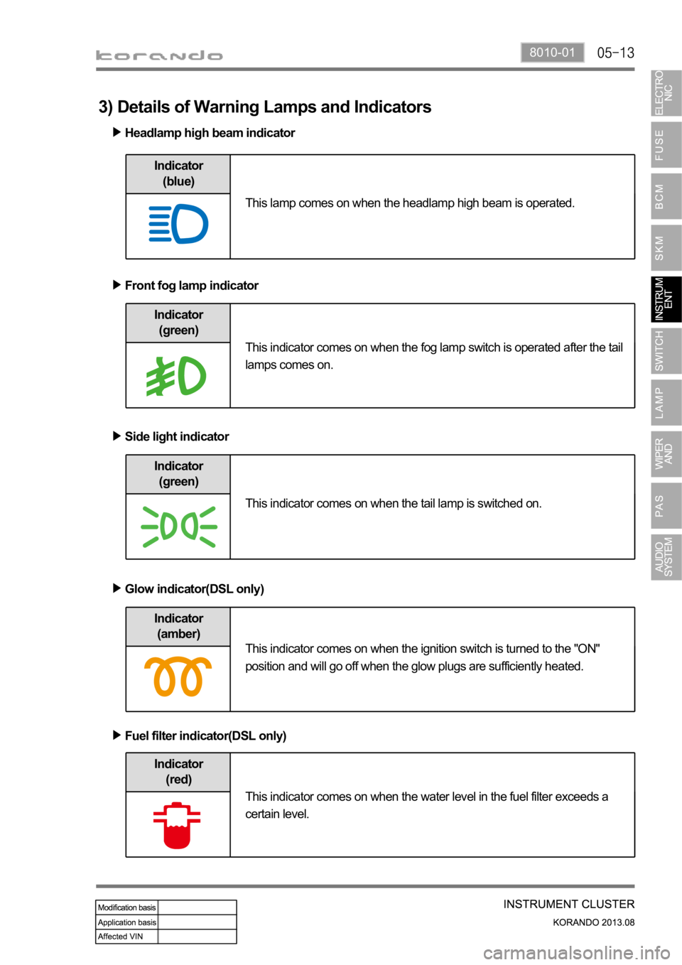
Indicator
(green)
Headlamp high beam indicator
Front fog lamp indicator
Side light indicator
Indicator
(blue)
Indicator
(green)
Indicator
(amber)
Glow indicator(DSL only)
Indicator
(red)
Fuel filter indicator(DSL only)
This indicator comes on when the tail lamp is switched on.
This indicator comes on when the ignition switch is turned to the "ON"
position and will go off when the glow plugs are sufficiently heated.
This indicator comes on when the water level in the fuel filter exceeds a
certain level. This lamp comes on when the headlamp high beam is operated.
This indicator comes on when the fog lamp switch is operated after the tail
lamps comes on.
3) Details of Warning Lamps and Indicators