SSANGYONG KYRON 2010 Service Manual
KYRON 2010
SSANGYONG
SSANGYONG
https://www.carmanualsonline.info/img/67/57505/w960_57505-0.png
SSANGYONG KYRON 2010 Service Manual
Trending: stop start, cooling, fuel, oil change, ESP, fuse, oil filter
Page 201 of 650
ENGINE FUEL SYSTEM
undefined
1881-01
5. COMPONENTS OF HIGH PRESSURE TRANSFER LINE
In the high pressure section, sufficient fuel pressure that injectors requires will be generated
and stored. The components are as below:
High pressure pump
Rail pressure sensor
Pressure limit valve
Common rail
High pressure pipe
Injector
Fuel pressure regulating valve (IMV) -
-
-
-
-
-
-
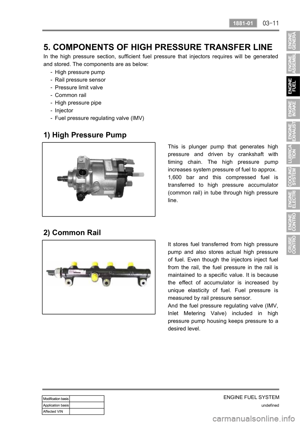
This is plunger pump that generates high
pressure and driven by crankshaft with
timing chain. The high pressure pump
increases system pressure of fuel to approx.
1,600 bar and this compressed fuel is
transferred to high pressure accumulato
r
(common rail) in tube through high pressure
line.
1) High Pressure Pump
It stores fuel transferred from high pressure
pump and also stores actual high pressure
of fuel. Even though the injectors inject fuel
from the rail, the fuel pressure in the rail is
maintained to a specific value. It is because
the effect of accumulator is increased by
unique elasticity of fuel. Fuel pressure is
measured by rail pressure sensor.
And the fuel pressure regulating valve (IMV,
Inlet Metering Valve) included in high
pressure pump housing keeps pressure to a
desired level.
2) Common Rail
Page 202 of 650
undefined
1881-01
ENGINE FUEL SYSTEM
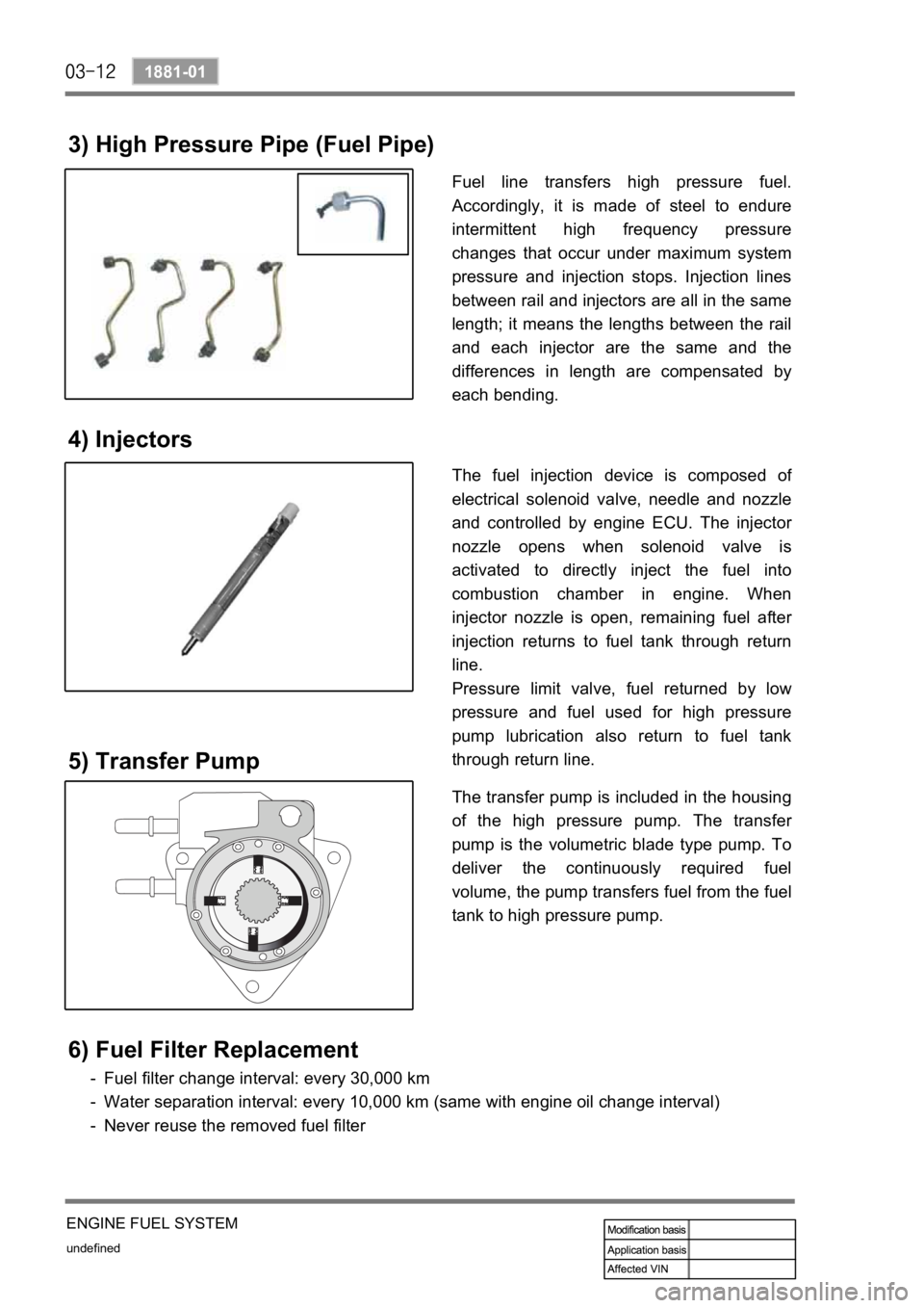
3) High Pressure Pipe (Fuel Pipe)
Fuel line transfers high pressure fuel.
Accordingly, it is made of steel to endure
intermittent high frequency pressure
changes that occur under maximum system
pressure and injection stops. Injection lines
between rail and injectors are all in the same
length; it means the lengths between the rail
and each injector are the same and the
differences in length are compensated by
each bending.
4) Injectors
The fuel injection device is composed of
electrical solenoid valve, needle and nozzle
and controlled by engine ECU. The injecto
r
nozzle opens when solenoid valve is
activated to directly inject the fuel into
combustion chamber in engine. When
injector nozzle is open, remaining fuel afte
r
injection returns to fuel tank through return
line.
Pressure limit valve, fuel returned by low
pressure and fuel used for high pressure
pump lubrication also return to fuel tank
through return line.
6) Fuel Filter Replacement
Fuel filter change interval: every 30,000 km
Water separation interval: every 10,000 km (same with engine oil change interval)
Never reuse the removed fuel filter -
-
-
The transfer pump is included in the housing
of the high pressure pump. The transfe
r
pump is the volumetric blade type pump. To
deliver the continuously required fuel
volume, the pump transfers fuel from the fuel
tank to high pressure pump.
5) Transfer Pump
Page 203 of 650
ENGINE FUEL SYSTEM
undefined
1881-01
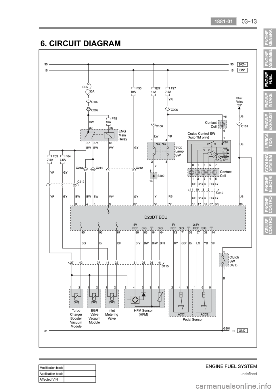
6. CIRCUIT DIAGRAM
Page 204 of 650
undefined
1881-01
ENGINE FUEL SYSTEM
Page 205 of 650
ENGINE FUEL SYSTEM
undefined
1881-01
Page 206 of 650
Page 207 of 650
ENGINE INTAKE SYSTEM
undefined
2321-01
GENERAL
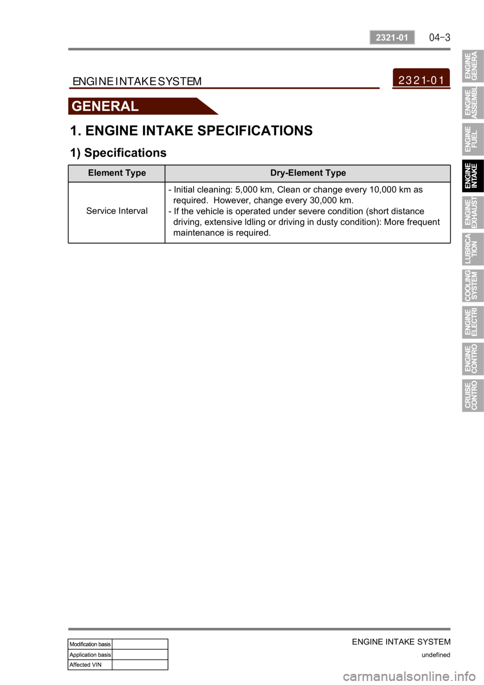
1. ENGINE INTAKE SPECIFICATIONS
1) Specifications
Element Type Dry-Element Type
Service Interval- Initial cleaning: 5,000 km, Clean or change every 10,000 km as
required. However, change every 30,000 km.
- If the vehicle is operated under severe condition (short distance
driving, extensive ldling or driving in dusty condition): More frequent
maintenance is required.
2321-01ENGINE INTAKE SYSTEM
Page 208 of 650
undefined
2321-01
ENGINE INTAKE SYSTEM
VGT Turbocharger
OVERVIEW AND OPERATION PROCESS
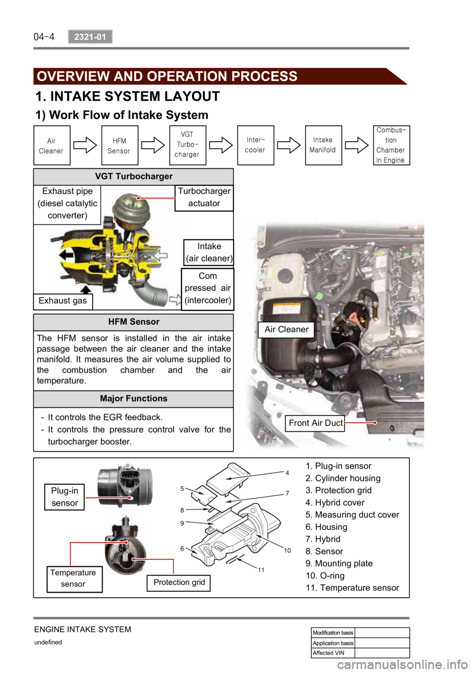
1. INTAKE SYSTEM LAYOUT
1) Work Flow of Intake System
HFM Sensor
The HFM sensor is installed in the air intake
passage between the air cleaner and the intake
manifold. It measures the air volume supplied to
the combustion chamber and the ai
r
temperature.
Major Functions
It controls the EGR feedback.
It controls the pressure control valve for the
turbocharger booster. -
-
1. Plug-in sensor
2. Cylinder housing
3. Protection grid
4. Hybrid cover
5. Measuring duct cover
6. Housing
7. Hybrid
8. Sensor
9. Mounting plate
10. O-ring
11. Temperature sensor
Turbocharger
actuator
Intake
(air cleaner)
Com
pressed air
(intercooler)
Exhaust gasExhaust pipe
(diesel catalytic
converter)
Plug-in
sensor
Temperature
sensorProtection grid
Front Air Duct Air Cleaner
Page 209 of 650
ENGINE INTAKE SYSTEM
undefined
2321-01
EGR Valve and Its Location
(* For details, refer to "EGR" section.)
Vacuum Modulator
Turbocharger Intercooler
The charging efficiency may be lowered or the
knocking may happen as the intake air is
heated and the density of air is lowered. The
intercooler is the device which cools the
supercharged air.
Intake
manifoldIntake
air
Exhaust
gasExhaust gasIntake manifold
Vacuum modulator
for turbocharger
actuator
EGR vacuum
modulator
Vacuum
pump EGR
valve
IP interior fuse (RH)
No.63-7.5AEngine ECU
No. 96
Intake Manifold
Intake air
Page 210 of 650
undefined
2321-01
ENGINE INTAKE SYSTEM
2) Layout
Trending: light, ECU, charging, engine, warning lights, fuel cap, stop start


