bearing SSANGYONG MUSSO 1998 Workshop Owner's Manual
[x] Cancel search | Manufacturer: SSANGYONG, Model Year: 1998, Model line: MUSSO, Model: SSANGYONG MUSSO 1998Pages: 1463, PDF Size: 19.88 MB
Page 188 of 1463

M162 ENGINE MECHANICAL 1B1-115
CYLINDER HEAD MATING SURFACE
Preceding Work : Removal of valves
Service Data Standard
Notice
Do not exceed 0.4mm for the milling of the mating surface of crankcase and cylinder head.Overall Height of Cylinder Head
Minimum Height After Machining
Flatness
Distance ‘T’
(Between Camshaft Bearing
and Valve Stem)Axial Direction
Transverse Direction
Standard Size
Repair Size135.9 - 136.0 mm
135.5 mm
0.08 mm
0.0 mm
24.21 - 24.75 mm
22.21 - 22.75 mm
23.96 - 24.51 mm
21.96 - 22.51 mm
Intake
Exhaust
Intake
Exhaust
Page 189 of 1463

1B1-116 M162 ENGINE MECHANICAL
Measurement of Mating Surface
1. Measure the height (H) of the cylinder head (refer to Service
data standard
).
2. Check the mating surface of the cylinder head.
3. Mill the sharp edge of the combustion chamber.
4. Re-measure the height (H) of the cylinder head.
5. Seal the intake and exhaust valves.
6. Measure the dimension (T) between the camshaft bearing
and the valve system (refer to
Service data standard).
7. Mill the cylinder head valve seat (refer to
Service data
standard
).
Universal Tool
Surface Grinding Machine
Sceledum, Type RTY
Roaro
Schio/Italy
Page 191 of 1463

1B2-2 M161 ENGINE MECHANICAL
SPECIFICATIONS
FASTENER TIGHTENING SPECIFICATIONS
N
· ·· ·
·m
35 - 40
10 - 15
5 - 10
21 - 25
30
56 - 66
50 - 60
22.5 - 27.5
41.5 - 49.5
22.5 - 27.5
22.5 - 27.5
9 - 11
9 - 11
9 - 11
9 - 11
22.5 - 27.5
10
+90°
55
+90°
+90°
22.5 - 27.5
22.5 - 27.5
9 - 10
9 - 10
200
+90°
40
+90°
45
+90°
35
9 - 11
20
+90°
20
+90°
20 / + 90°
20 / + 90°
22.5 - 27.5Application
Power Steering Hydraulic Lines
A/C High Pressure and Liquid Hose
Radiator Support Menber Bolt
Fuel Supply and Return Hose to Fuel Distributor
Exhaust Manifold and Pipe
Propeller Shaft to Transmission
Engine Mounting Nut
Alternator Carrier Bolt
Belt Pulley Bolt
Steering Pump Bolt
A/C Bracket Bolt
Intake Air Duct Bolt
Ignition Cable Cover Bolt
Cylinder Head Cover Bolt
Camshaft Adjuster Bolt
Cylinder Head Front Cover Bolt
Flange Bolt in Exhaust Camshaft Sprocket
Cylinder Head Bolt
Cooling Fan Bracket Bolt
Timing Gear Case Cover Bolt M8
M6
Crankshaft Rear Cover Bolt
Vibration Damper Center Bolt
Connecting Rod Bearing Cap Bolt
Flywheel Stretch Bolt
Amarture Bolt in Flywheel
Ring and Seal Cover Nut in Flywheel
Sprocket Bolt to Exhaust Camshaft
Camshaft Adjuster Flange Bolt
Intake Flange Shaft Bolt
Exhaust Camshaft Sprocket Bolt
Camshaft Bearing Cap Bolt
Page 217 of 1463

1B2-28 M161 ENGINE MECHANICAL
POLY V-BELT
Preceding Work : Removal of cooling fan
1 Poly V-belt (2,155 mm)
2 Belt Tensioning Pulley
Removal & Installation Procedure
1. Release the belt tension by turning the stud on the cap with
12 sided wrench or spanner counterclockwise.
2. Remove the poly v-belt.
Notice
Check the belt for damage and tensioning pulley bearing
point for wear and replace them if necessary.
3. Install the belt after prying the tensioning pulley.
3 Belt Tensioner
Page 228 of 1463

M161 ENGINE MECHANICAL 1B2-39
CYLINDER HEAD
Preceding Work : Removal of cylinder head cover
Removal of cylinder head front cover
Removal of intake manifold
Removal of cylinder head lower line (intake manifold side)
1 Cylinder Head Bolt (M12 X 100, 10 pieces)
....................................................1st step 55 Nm
2nd step 90° rotation added
3rd step 90° rotation added
3 Bolt (M8 X 35, 4 pieces).................22.5-27.5 Nm4 Camshaft Bearing cap...................22.5-27.5 Nm
5 Cylinder Head
6 Gasket ................................................... Replace
7 Dowel Sleeve...............................................Note
Page 229 of 1463

1B2-40 M161 ENGINE MECHANICAL
Tools Required
617 589 00 10 00 Wrench Socket
116 589 2 0 33 00 Sliding Hammer
116 589 01 34 00 Threaded Bolt
001 589 66 21 00 Torque Wrence
104 589 00 40 00 Holder
Removal & Installation Procedure
1. Rotate the crankshaft so that the piston of number 1 cylinder
is at ATDC 20.
2. Put the pin into the camshaft bearing cap (number 1, 6).
Pin 111 589 03 15 00
3. Put the alignment marks (arrows) on the timing chain and
camshaft sprocket.
4. Remove the chain tensioner.
Installation Notice
Tightening Torque 72 - 88 Nm
Tightening Torque1st step 18 - 22 Nm
2nd step 85° - 95°
5. Remove the exhaust camshaft sprocket.
Installation Notice
Notice
The flange bolt is designed to be used only once, so always
replace with new one.
Page 231 of 1463

1B2-42 M161 ENGINE MECHANICAL
10. Remove the cylinder head bolts in the reverse order of
the numerics (No.10 ® No.1).
Installation Notice
Tighten the bolts as numerical order with specified torque
(No.1 ® No.10).
Holder 104 589 00 40 00
1 Cylinder Head Bolt
2 M8 X 35 Bolt & Washer
3 Bearing Cap
4 Engine Hoist
5 Gasket
6 Hanger Bracket
Tightening Torque1st step 55 ± 5 Nm
2nd step + 90°
3rd step + 90°
11. Remove the No. 1 bearing cap of the exhaust camshaft.
Installation Notice
Tightening Torque 22.5 - 27.5 Nm
12. Install the special tool (05) on the bearing cap removed
place and hook the engine hoist into them and remove
the cylinder head carefully.
13. Check the cylinder head mating surface and clean the
crankcase head bolt mounting hole.
14. Replace the cylind head gasket with new one.Notice
Operate during engine cooling.
Page 243 of 1463

1B2-54 M161 ENGINE MECHANICAL
CRANKSHAFT
Preceding Work : Removal of engine
Removal of cylinder head
Removal of timing gear case cover
Removal of crankcase sealing rear cover
Removal of oil pan
Removal of baffle plate
Removal of oil pump
1 Bearing Cap Bolt
(M8 X 55-10 pieces) ............ 1st step 50-60 Nm
2nd step 90°+5° rotation added
2 Bearing Cap
3 Upper Main Bearing
4 Lower Main Bearing
5 Upper Thrust Bearing
6 Lower Thrust Bearing
8 Crank Shaft
Page 244 of 1463

M161 ENGINE MECHANICAL 1B2-55
Arrangement of the Thrust Bearing and the Main Bearing
1 - 8 Weight Balance/Color Marking Point
j1 - j5 Journal Main Bearing #1 - #5
lColor Dot Marking
The color dot marking are put on the 1 , 2 , 4 , 6
, 8 , and it indicates the diameter of crankshaft journal
by color as below.A Crankcase Side
B Bearing Cap Side (Oil Pan Side)
1 Upper Main Bearing
2 Upper Thrust Bearing
3 Crankshaft
4 Lower Main Bearing
5 Lower Thrust Bearing
Page 245 of 1463
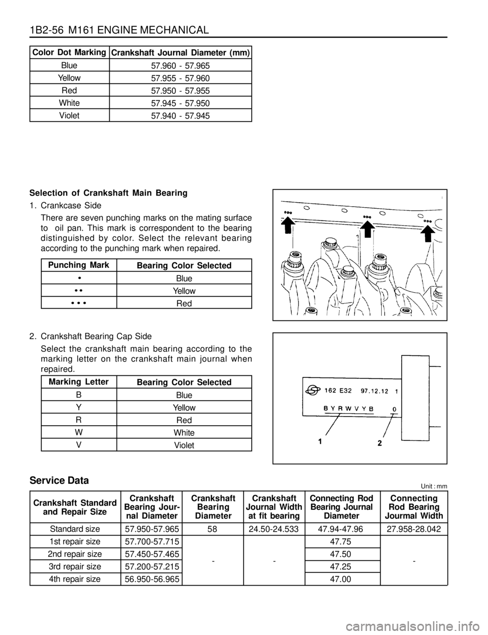
1B2-56 M161 ENGINE MECHANICAL
Selection of Crankshaft Main Bearing
1. Crankcase Side
There are seven punching marks on the mating surface
to oil pan. This mark is correspondent to the bearing
distinguished by color. Select the relevant bearing
according to the punching mark when repaired.
2. Crankshaft Bearing Cap Side
Select the crankshaft main bearing according to the
marking letter on the crankshaft main journal when
repaired.
Color Dot Marking
Blue
Yellow
Red
White
VioletCrankshaft Journal Diameter (mm)
57.960 - 57.965
57.955 - 57.960
57.950 - 57.955
57.945 - 57.950
57.940 - 57.945
Punching Mark
·
··
···
Bearing Color Selected
Blue
Yellow
Red
Marking Letter
B
Y
R
W
VBearing Color Selected
Blue
Yellow
Red
White
Violet
Service DataUnit : mm
Crankshaft
Bearing Jour-
nal DiameterCrankshaft
Bearing
DiameterCrankshaft
Journal Width
at fit bearingConnecting Rod
Bearing Journal
DiameterConnecting
Rod Bearing
Jourmal Width
Standard size
1st repair size
2nd repair size
3rd repair size
4th repair size57.950-57.965
57.700-57.715
57.450-57.465
57.200-57.215
56.950-56.96558 24.50-24.533 47.94-47.96
47.75
47.50
47.25
47.0027.958-28.042 Crankshaft Standard
and Repair Size
- --