ECS SSANGYONG MUSSO 2003 Service Manual
[x] Cancel search | Manufacturer: SSANGYONG, Model Year: 2003, Model line: MUSSO, Model: SSANGYONG MUSSO 2003Pages: 1574, PDF Size: 26.41 MB
Page 538 of 1574
1F1-6 M162 ENGINE CONTROLSDIAGNOSIS
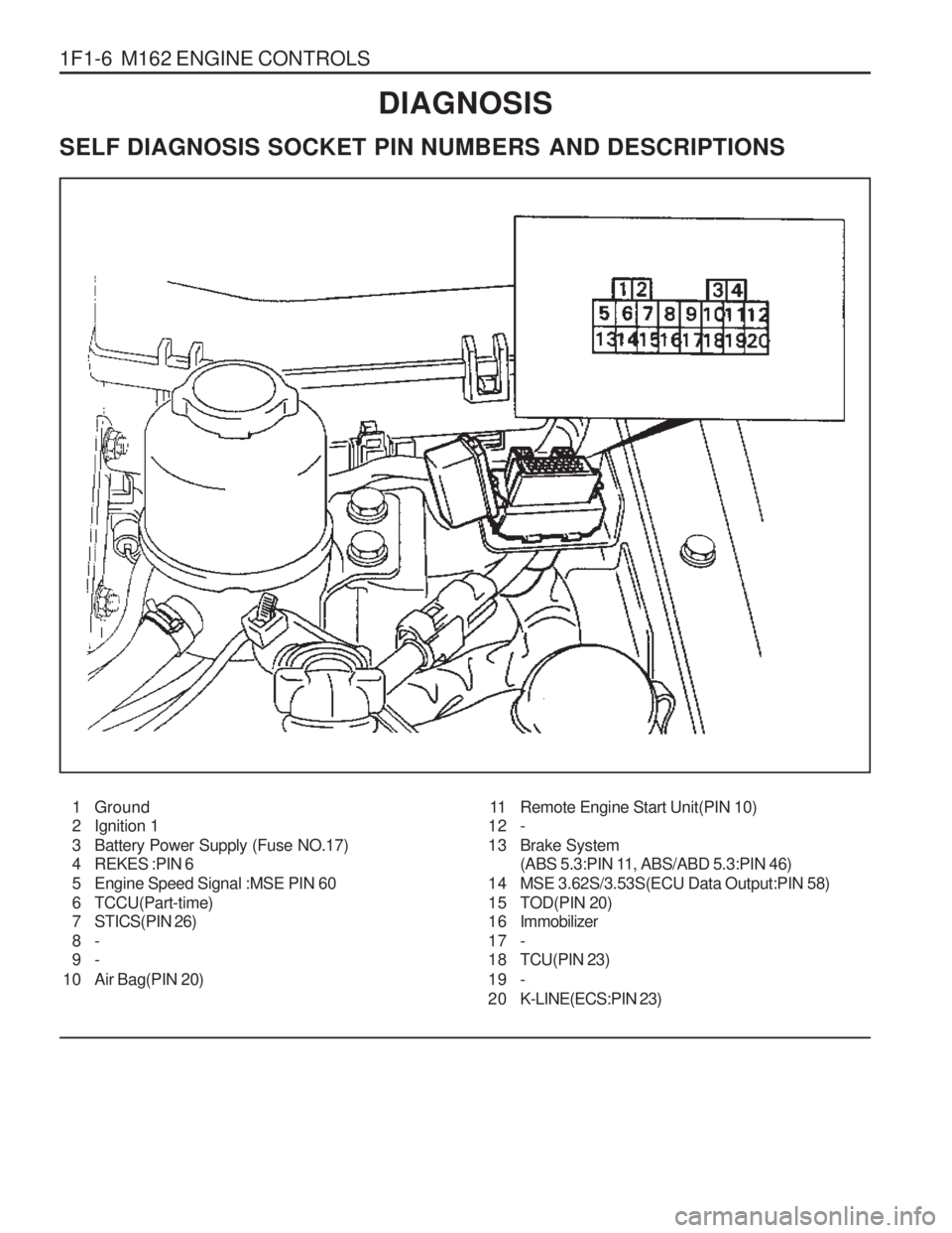
SELF DIAGNOSIS SOCKET PIN NUMBERS AND DESCRIPTIONS
1 Ground
2 Ignition 1
3 Battery Power Supply (Fuse NO.17)
4 REKES :PIN 6
5 Engine Speed Signal :MSE PIN 60
6 TCCU(Part-time)
7 STICS(PIN 26) 8- 9-
10 Air Bag(PIN 20) 11 Remote Engine Start Unit(PIN 10)
12 -
13 Brake System (ABS 5.3:PIN 11, ABS/ABD 5.3:PIN 46)
14 MSE 3.62S/3.53S(ECU Data Output:PIN 58)
15 TOD(PIN 20)
1 6 Immobilizer
17 -
18 TCU(PIN 23)
19 -
2 0 K-LINE(ECS:PIN 23)
Page 698 of 1574

SECTION 2A
SUSPENSION DIAGNOSIS
TABLE OF CONTENTS
Specifications . . . . . . . . . . . . . . . . . . . . . . . . 2A-1
General Specifications . . . . . . . . . . . . . . . . . . 2A-1
Diagnosis . . . . . . . . . . . . . . . . . . . . . . . . . . . 2A-3
General Diagnosis . . . . . . . . . . . . . . . . . . . . . 2A-3
Input & Output Devices and Damping Force Control Logic . . . . . . . . . . . . . . . . . 2A-5
Input & Output Devices . . . . . . . . . . . . . . . . . . 2A-5
System Layout . . . . . . . . . . . . . . . . . . . . . . . . 2A-5Damping Force Control Logic . . . . . . . . . . . . . 2A-6
Normal Control . . . . . . . . . . . . . . . . . . . . . . . . 2A-6
Self-Diagnosis . . . . . . . . . . . . . . . . . . . . . . . . 2A-7
Actuator Inspection . . . . . . . . . . . . . . . . . . . . . 2A-8
Schematic and Routing Diagrams . . . . . . . . 2A-9
ECS Circuit . . . . . . . . . . . . . . . . . . . . . . . . . . . 2A-9
Self Diagnosis Test . . . . . . . . . . . . . . . . . . 2A-12
Diagnosis Test . . . . . . . . . . . . . . . . . . . . . . . 2A-12
SPECIFICATIONS
GENERAL SPECIFICATIONS
188
Application
Front
3-stage Variable Damping Force Control Type Rear
ECS Control Type
344 - 350
Shock Absorber517 - 523
Max. Length (mm)
245 ± 3
Compressed Length (mm) 102
Stroke (mm)331 ± 3
Page 702 of 1574
SUSPENSION DIAGNOSIS 2A-5
INPUT & OUTPUT DEVICES AND DAMPING FORCECONTROL LOGIC
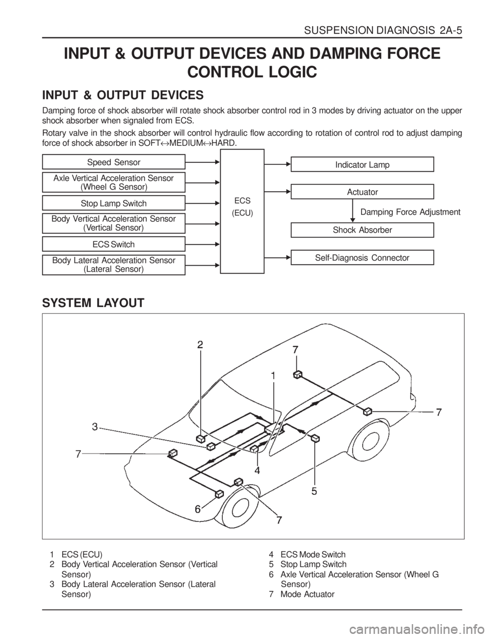
INPUT & OUTPUT DEVICES Damping force of shock absorber will rotate shock absorber control rod in 3 modes by driving actuator on the upper shock absorber when signaled from ECS. Rotary valve in the shock absorber will control hydraulic flow according to rotation of control rod to adjust damping force of shock absorber in SOFT MEDIUM HARD.
SYSTEM LAYOUT
1 ECS (ECU)
2 Body Vertical Acceleration Sensor (Vertical Sensor)
3 Body Lateral Acceleration Sensor (Lateral
Sensor)
Speed Sensor
Axle Vertical Acceleration Sensor (Wheel G Sensor)
Stop Lamp Switch
Body Vertical Acceleration Sensor (Vertical Sensor)
ECS Switch
Indicator Lamp
Actuator
Shock Absorber
Self-Diagnosis Connector
Damping Force Adjustment
ECS
(ECU)
Body Lateral Acceleration Sensor (Lateral Sensor)
4 ECS Mode Switch
5 Stop Lamp Switch
6 Axle Vertical Acceleration Sensor (Wheel G
Sensor)
7 Mode Actuator
Page 704 of 1574
SUSPENSION DIAGNOSIS 2A-7
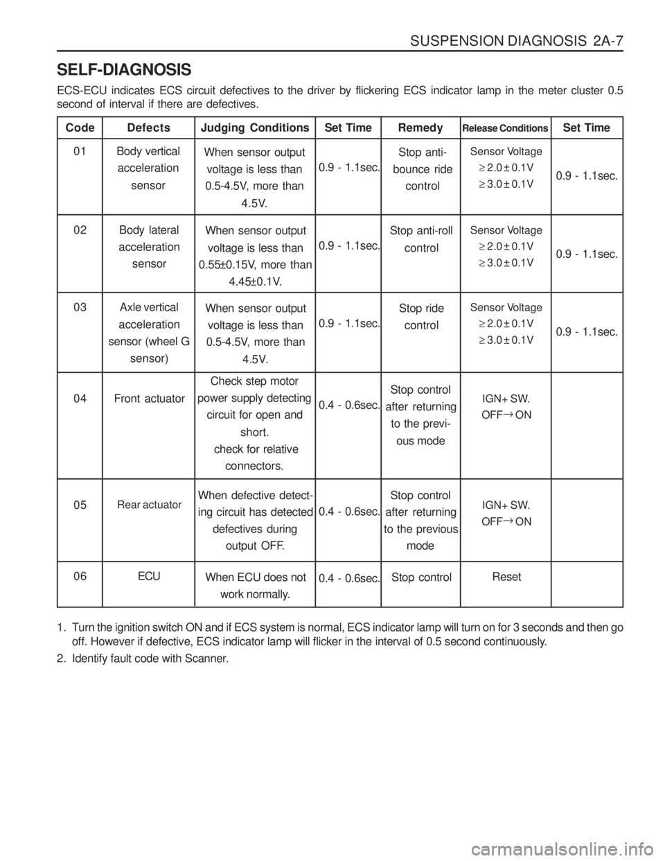
SELF-DIAGNOSIS ECS-ECU indicates ECS circuit defectives to the driver by flickering ECS indicator lamp in the meter cluster 0.5 second of interval if there are defectives.
Code
Body verticalacceleration
sensor
Defects
When sensor outputvoltage is less than
0.5-4.5V, more than
4.5V.
Judging Conditions01
0.9 - 1.1sec.Set TimeSensor Voltage
2.0 ± 0.1V
3.0 ± 0.1V
Release Conditions
0.9 - 1.1sec.
Set Time
Body lateral
acceleration sensor When sensor output
voltage is less than
0.55±0.15V, more than
4.45±0.1V.
02
0.9 - 1.1sec.Sensor Voltage
2.0 ± 0.1V
3.0 ± 0.1V 0.9 - 1.1sec.
Stop anti-
bounce ride
control
Remedy
Stop anti-roll control
Axle vertical
acceleration
sensor (wheel G sensor) When sensor output
voltage is less than
0.5-4.5V, more than
4.5V.
03
0.9 - 1.1sec.Sensor Voltage
2.0 ± 0.1V
3.0 ± 0.1V 0.9 - 1.1sec.
Stop ride
control
Front actuator Check step motor
power supply detecting
circuit for open and
short.
check for relative connectors.
04
0.4 - 0.6sec.IGN+ SW.
OFF
ON
Stop control
after returning to the previ-
ous mode
Rear actuator When defective detect- ing circuit has detected
defectives during
output OFF.
05
0.4 - 0.6sec.IGN+ SW.
OFF
ON
Stop control
after returning
to the previous
mode
ECU When ECU does not
work normally.
06
0.4 - 0.6sec.Reset
Stop control
1. Turn the ignition switch ON and if ECS system is normal, ECS indicator lamp will turn on for 3 seconds and then go off. However if defective, ECS indicator lamp will flicker in the interval of 0.5 second continuously.
2. Identify fault code with Scanner.
Page 706 of 1574
SUSPENSION DIAGNOSIS 2A-9
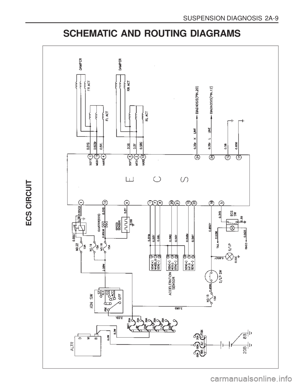
ECS CIRCUIT
SCHEMATIC AND ROUTING DIAGRAMS
Page 709 of 1574
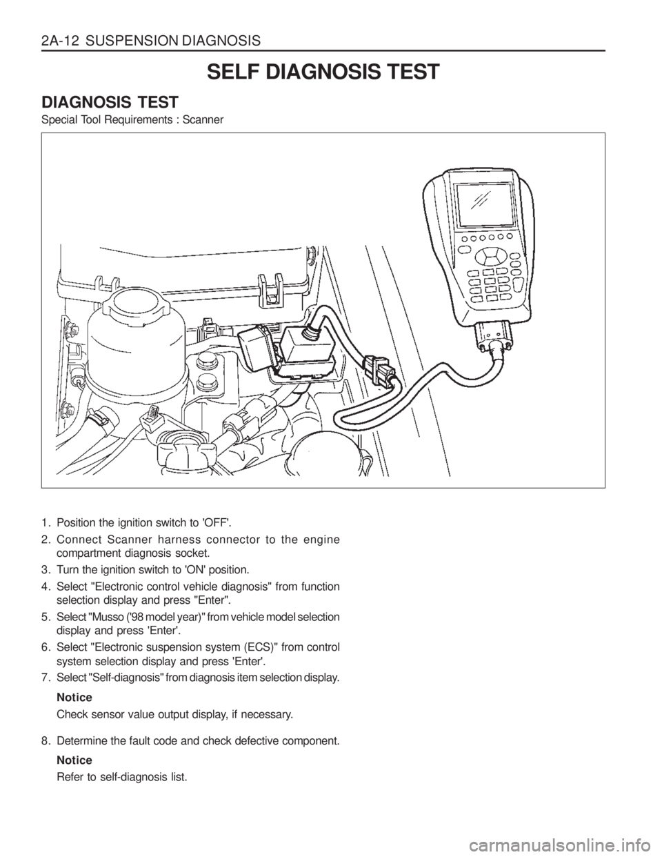
2A-12 SUSPENSION DIAGNOSISSELF DIAGNOSIS TEST
DIAGNOSIS TEST
Special Tool Requirements : Scanner
1. Position the ignition switch to 'OFF'.
2. Connect Scanner harness connector to the engine compartment diagnosis socket.
3. Turn the ignition switch to 'ON' position.
4. Select "Electronic control vehicle diagnosis" from function selection display and press "Enter".
5. Select "Musso ('98 model year)" from vehicle model selection display and press 'Enter'.
6. Select "Electronic suspension system (ECS)" from control system selection display and press 'Enter'.
7. Select "Self-diagnosis" from diagnosis item selection display.
Notice
Check sensor value output display, if necessary.
8. Determine the fault code and check defective component. NoticeRefer to self-diagnosis list.
Page 720 of 1574

SECTION 2C
FRONT SUSPENSION
TABLE OF CONTENTSSPECIFICATIONS
GENERAL SPECIFICATIONS
Type
Spring Type
Torsion Bar Shock Absorber
Stabilizer Type
Double Wishbone
Torsion Bar Spring 1,040 mm
24.5 mm
Cylindrical Reciprocation Type
Torsion Bar Spring
Specifications . . . . . . . . . . . . . . . . . . . . . . . . 2C-1General Specifications . . . . . . . . . . . . . . . . . . 2C-1
Fastener Tightening Specifications . . . . . . . . . 2C-2
Component Locator . . . . . . . . . . . . . . . . . . . 2C-3
Front Suspension . . . . . . . . . . . . . . . . . . . . . . 2C-3
Maintenance and Repair . . . . . . . . . . . . . . . 2C-4
On-Vehicle Service . . . . . . . . . . . . . . . . . . . . . 2C-4
Front Stabilizer Bar . . . . . . . . . . . . . . . . . . . . . 2C-4
Application Description
Torsion Bar . . . . . . . . . . . . . . . . . . . . . . . . . . . 2C-6
Front Lower and Upper Arm . . . . . . . . . . . . . . 2C-8
Front Shock Absorber . . . . . . . . . . . . . . . . .
2C-10
Axle Vertical Acceleration Sensor (Wheel G Sensor) . . . . . . . . . . . . . . . . . . . 2C-12
Vertical and Lateral Sensor . . . . . . . . . . . . . . 2C-13
ECS (ECU) . . . . . . . . . . . . . . . . . . . . . . . . . . 2C-14
Length Outer Diameter(
)
Page 733 of 1574

2C-14 FRONT SUSPENSION ECS (ECU)1 Electronically Controlled Suspension (ECU)
2 Connector
3 Bolts (2 pieces)
Removal & Installation Procedure
1. Disconnect each connectors from the console box and remove the console box.
2. Disconnect ECU connector.
3. Unscrew 10mm x 2 bolts and remove ECS (ECU).
4. Installation should follow the removal procedure in the reverse order.
4 Parking Brake Lever
5 Over Voltage Protection Relay
Page 1208 of 1574

9A-6 BODY WIRING SYSTEM Engine Room Fuse (EF) and Relay Box1 Fuse (15A) : ABS, ABD
2 Fuse (20A) : Sun Roof
3 Fuse (10A) : Air Bag
4 Fuse (15A) : Audio, Clock, Out Side Mirror
5 Fuse (30A) : Cigarette lighter, Power Socket
6 Fuse (30A) : Heater
7 Fuse (15A) : Door Lock
8 Fuse (30A) : Rear Heated
9 Fuse (10A) : Audio, Buzzer, Chime, Clock
10 Fuse (30A) : Power Window
11 Fuse (10A) : Immobilizer
12 Fuse (20A) : T/C
13 Fuse (15A) : Interior Lamp
14 Fuse (15A) : Hazard Lamp
15 Fuse (15A) : Stop Lamp
16 Fuse (15A) : Turn signal Lamp, Head Lamp
17 Fuse (10A) : Back up Lamp
18 Fuse (15A) : Cluster, STICS
19 Fuse (15A) : A/T, Diagnosis
20 Fuse (15A) : Over Voltage Protection Relay (Gasolin Only)
21 Fuse (15A) : Seat Heater
22 Fuse (15A) : ECS
23 Fuse (15A) : Front Wiper & Washer
24 Fuse (10A) : Rear Wiper & Washer, A/C
25 Relay : Front Wiper 26 Relay : ABS Warning Lamp
27 Relay : Flasher Unit
28 Relay : Fuel Pump (Gasoline Only)
29 Relay : Shift Lock (A/T)
30 Relay : Clutch Interlock & Neutral
31 Relay : Sun Roof
32 Relay : A/T ‘B’ Interlock (MB A/T)
33 Relay : Power Window
34 Relay : Rear Fog Lamp
35 Relay : ECS
36 Relay : Compressor (Diesel E/G)
Condenser Fan (Gasoline E/G)
37 Relay : Condenser Fan
38 Relay : Air Conditioner
39 Fuse (10A) : Tail Lamp
40 Fuse (15A) : Head Lamp(LH)
41 Fuse (15A) : Head Lamp(RH)
42 Fuse (15A) : Front Fog Lamp
43 Fuse (10A) : Horn
44 Fuse (10A) : Compressor
45 Relay : Resistor with Diode (Gasoline E/G)
46 Relay : Front fog Lamp
47 Relay : Condenser Fan
48 Relay : Tail Lamp
49 Relay : Horn
Page 1210 of 1574

9A-8 BODY WIRING SYSTEM1 Fuse Box
2 Door Lock Relay
3 Relay Box
3.1 Front Wiper Relay
3.2 ABS Warning Lamp Relay ....................................ABD 5.0
3.3 Flasher Unit
3.4 Fuel Pump Relay ................................................. Gasoline E/G
3.5 Shift Lock Relay ................................................... Automatic Transmission
3.6 Clutch Interlock & Neutral Relay ...........................Manual Transmission or Automatic Transmission
3.7 Sun Roof Relay
3.8 Automatic T ransmission ‘B’ Switch Interlock ....... Automatic Transmission
3.9 Power Window Relay
3.10 Rear Fog Lamp Relay .......................................... Rear Fog Lamp
3.11 ECS Relay 4 Defogger Relay
5 Ground 1
6 Roof Wiring Connector
7 Diode 1
8 Front Door Wiring Connector
9 Front Door Wiring Connector
10 Front Door Wiring Connector 11 Front Door Wiring Connector
12 Kick Down Relay .................................................. Automatic Transmission
13 Floor Wiring Connector
14 Floor Wiring Connector
15 Floor Wiring Connector
16 ABD Floor Wiring Connector ................................ABD 5.0
17 ECS Floor Wiring Connector
18 Rear Iper & Washer Switch
19 Clutch Switch ........................................................ Manual Transmission
19-1 Clutch Switch ........................................................ E32 Gasoline E/G with Manual Transmission
20 Stop Lamp Switch
21 Outside Mirror Switch
22 Ignition Switch
23 Multi Function Switch
24 Multi Function Switch
25 Black Out Switch .................................................. Black Out Lamp
26 Black out switch ................................................... Black Out Lamp
27 Joint Connector (Tail)
28 Joint Connector (Ignition)
29 Cluster
30 Cluster ................................................................. Automatic Transmission
31 Cluster
32 Cluster
33 4WD Switch .......................................................... Except TOD
33-1 4WD Switch .......................................................... TOD
3 4 Hazard Switch
35 Ground 2
36 Pedal Module ....................................................... Gasoline E/G with MSE ECU
37 Audio Switch
3 8 Immobilizer ........................................................... Crypto Type, Gasoline E/G with MSE ECU or Diesel E/G
39 Ignition Switch
40 Multi Function Switch
4 1 STICS
4 2 STICS
4 3 REKES ................................................................. Remote Keyless