wiring diagram SSANGYONG MUSSO 2003 Service Manual
[x] Cancel search | Manufacturer: SSANGYONG, Model Year: 2003, Model line: MUSSO, Model: SSANGYONG MUSSO 2003Pages: 1574, PDF Size: 26.41 MB
Page 511 of 1574

M162 ENGINE ELECTRICAL 1E1-11
Circuit Diagram
Inspection & Maintenance Procedure (for MSE)
1. While the ignition switch is in 'OFF' position, remove thewiring connectors (1 and 15) from ignition coil and measure the primary resistance between terminal No.1 and No.15.
2. During engine cranking, measure primary voltage (T1/1) between ECU terminal No. 71 and No. 69.
Notice If out of specified value, replace the ignition coil.
Specified Value
0.9 - 1.6 � (20 °C)
Specified Value 200 - 350 V
Notice
� Measure remaining cables.
- T1/2 : No. 72 and 69.
- T1/3 : No. 70 and 69.
� If out of specified value, check ignition cable and ECU.
3. Using a multi-tester, measure the secondary coil resistance between 5a and 5b.
Specified Value 6 - 8.5 k�
Page 1095 of 1574

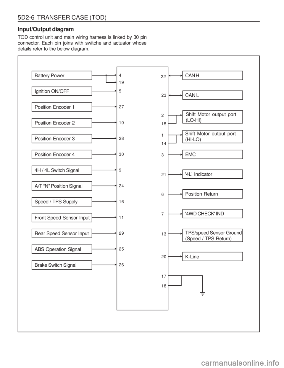
5D2-6 TRANSFER CASE (TOD) Input/Output diagram TOD control unit and main wiring harness is linked by 30 pin
connector. Each pin joins with switche and actuator whosedetails refer to the below diagram.
Battery Power
Ignition ON/OFF
Position Encoder 1
Position Encoder 2
Position Encoder 3
Position Encoder 4
4H / 4L Switch Signal
A/T “N” Position Signal
Speed / TPS Supply
Front Speed Sensor Input
Rear Speed Sensor Input
ABS Operation Signal
Brake Switch Signal
4 5271028309241611292526
19 CAN H
CAN L
Shift Motor output port (LO-HI)
Shift Motor output port (HI-LO)
EMC
'4L' Indicator
Position Return
'4WD CHECK' IND
TPS/speed Sensor Ground (Speed / TPS Return)
2 13216713
1514
K-Line
20
22
23
17 18
Page 1203 of 1574

SECTION 9A
BODY WIRING SYSTEM
Schematic and Routing Diagrams . . . . . . . . 9A-2
Power Distribution . . . . . . . . . . . . . . . . . . . . . . 9A-2
Starting & Charging (Gasoline HFM) . . . . . . . 9A-3
Starting & Charging (Diesel) . . . . . . . . . . . . . . 9A-4
Fuse Box and Relay . . . . . . . . . . . . . . . . . . . 9A-5
Location of Connectors by
Wiring Harness . . . . . . . . . . . . . . . . . . . . . 9A-7
Main . . . . . . . . . . . . . . . . . . . . . . . . . . . . . . . . 9A-7
Engine Room . . . . . . . . . . . . . . . . . . . . . . . . 9A-11
Floor . . . . . . . . . . . . . . . . . . . . . . . . . . . . . . . 9A-13
Roof . . . . . . . . . . . . . . . . . . . . . . . . . . . . . . . 9A-14
Driver's Door . . . . . . . . . . . . . . . . . . . . . . . . . 9A-15
Passenger's Door . . . . . . . . . . . . . . . . . . . . . 9A-15
TABLE OF CONTENTS
Caution: Disconnect the negative battery cable before removing or installing any electrical unit or when a tool or equipment could easily come in contact with exposed electrical terminals. Disconnecting this cable will help prevent personal injury and damage to the vehicle. The ignition must also be in LOCK unless otherwisenoted.
Rear Left Door . . . . . . . . . . . . . . . . . . . . . . . 9A-16
Rear Right Door . . . . . . . . . . . . . . . . . . . . . . 9A-16
Tail Gate . . . . . . . . . . . . . . . . . . . . . . . . . . . . 9A-17
Semi Automatic Air Conditioner . . . . . . . . . . 9A-18
Full automatic Air Conditioner . . . . . . . . . . . . 9A-19
Gasoline Engine (MSE) . . . . . . . . . . . . . . . . 9A-20
Gasoline Engine (HFM) . . . . . . . . . . . . . . . . 9A-21
Diesel Engine . . . . . . . . . . . . . . . . . . . . . . . . 9A-22
Manual Transmission . . . . . . . . . . . . . . . . . . 9A-23
Automatic Transmission (BENZ) . . . . . . . . . . 9A-24
Automatic Transmission (BTRA) . . . . . . . . . . 9A-25
Driver's Seat . . . . . . . . . . . . . . . . . . . . . . . . . 9A-26
Page 1204 of 1574

9A-2 BODY WIRING SYSTEMSCHEMATIC AND ROUTING DIAGRAMS
POWER DISTRIBUTION
Page 1340 of 1574

1A-28 MUSSO-SPORTS
SUPPLEMENT
30 BAT+
15 IGN 1
58 ILL
31 GND
2 3
107
B E
ClusterL
20 388
6 B4
B2 Multi-Function Switch
(Turn Signal Switch)
GY GY B1
RH
LH
5 9
ILL OFF ON
4
Hazard
Switch
G204 G301
G201
E
f10
10A
F2110A E
f9
60A
F7 15A
1 GW
YB BG RG
GW LY
GL YW
B
BB
B Blinker Unit Y
W
GR
GR
4
S202 E
f2 80A
2 4G
G W
G
G
1 2
G
G102 G204
3 1
G303
24
G101
G101 31
FRT LH
Turn Signal Lamp
(Head Lamp)
RR LH
Turn SignalLamp
(Tail Lamp) FRT RH
Turn Signal Lamp
(Head Lamp)
RR RH
Turn SignalLamp
(Tail Lamp)
"28"
Cluster
YYY
B
B
B "25"
Cluster
C905 2
C203
5
C904 2 C108
C206
C905 8
3 C904
3
C101
4
C1031
11C905
6
C101
17
Fender Fender
C904
7
ELECTRICAL WIRING DIAGRAM
1. TURN SIGNAL LAMP, HAZARD LAMP CIRCUIT
Page 1348 of 1574

1. HOW TO READ ELECTRICAL WIRING DIAGRAM ........................ 1-2
2. CIRCUIT IDENTIFICATION SYMBOL ............................................... 1-3
3. FUNCTION OF POWER SUPPLY LINE ............................................ 1-3
4. WIRING HARNESS COLOR IDENTIFICATION................................ 1-3
5. HOW TO CHECK TERMINAL NUMBER OF CONNECTOR .......... 1-3 CONTENTS
SECTION 1
HOW TO USE ELECTRICAL WIRING DIAGRAM
Page 1349 of 1574

1-2 HOW TO USE ELECTRICAL WIRING DIAGRAM
1. HOW TO READ ELECTRICAL WIRING DIAGRAM1) CONTENTS OF ELECTRICAL WIRING DIAGRAM (CIRCUIT)
POSITION EXPLANATION
- Upper horizontal lines : Power supply lines
- Power supply lines : 30, 15, 15A, 15C, 58
- Ef20 or F2 : Fuse Number
• Ef20 : Fuse No #20 in engine room compartment
F2 : Fuse No #2 in passenger room compartment
- Connector (C101~C901) Connector No C203 terminal No1
* Refer to Major Connector Position (Section 2)
- S201 : Splice pack (S101~S306) * Refer to Major Splice Pack Position (Section2)
- Wiring Harness Color * Refer to Wiring Harness Color Abbreviation
- Internal circuit of component (Relay) (Component Name and Terminal Number)
- Internal circuit of component (Switch) (Component Name, Terminal Number and Connecting Wiring Circuit)
- J201 : Joint(J101~J401) * Refer to Major Joint Position(Section2)
- Lower horizontal line : Ground line Ground position(G101~G402)
B : Body Ground
* Refer to Major Ground Position (Section2)
A
B C D E
F
G
H
I
A
B
C
D F
G
E I
H
Page 1350 of 1574

HOW TO USE ELECTRICAL WIRING DIAGRAM 1-3
Connector DiodeFuse in engine room fuse & relay box Fuse in passenger room fuse box Ground Joint - Inline wire connected point Splice pack(Junction connector)
C D
Ef F
G J
S
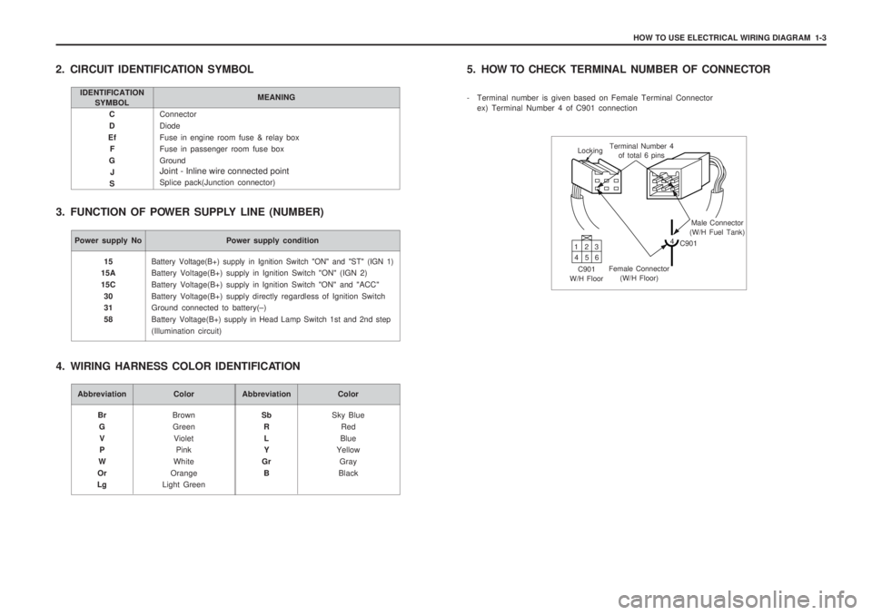
2. CIRCUIT IDENTIFICATION SYMBOL
3. FUNCTION OF POWER SUPPLY LINE (NUMBER)
IDENTIFICATION SYMBOL MEANING
Power supply No Power supply condition
Battery Voltage(B+) supply in Ignition Switch "ON" and "ST" (IGN 1)
Battery Voltage(B+) supply in Ignition Switch "ON" (IGN 2) Battery Voltage(B+) supply in Ignition Switch "ON" and "ACC"Battery Voltage(B+) supply directly regardless of Ignition Switch Ground connected to battery(
–)
Battery Voltage(B+) supply in Head Lamp Switch 1st and 2nd step
(Illumination circuit)
15
15A 15C
30 31 58
Abbreviation Color
BrownGreen Violet Pink
White
Orange
Light Green
Br
GV P
W
Or
LgAbbreviation Color
Sky BlueRed
Blue
Yellow
Gray
Black
Sb
RL Y
Gr B
4. WIRING HARNESS COLOR IDENTIFICATION 5. HOW TO CHECK
TERMINAL NUMBER OF CONNECTOR
- Terminal number is given based on Female Terminal Connector ex) Terminal Number 4 of C901 connection
Locking Terminal Number 4
of total 6 pins
Male Connector
(W/H Fuel Tank)
4 C901
Female Connector (W/H Floor)
C901
W/H Floor 13
2
46 5
Page 1359 of 1574

CONTENTS
1. FUSIBLE LINK FUSE BLOCK & ENGINE ROOM FUSE BLOCK POWER DISTRIBUTION .................................................... 3-2
2. I/P FUSE BLOCK POWER DISTRIBUTION ..................................... 3-3
SECTION 3
WIRING DIAGRAM FOR POWER SUPPLIES
Page 1360 of 1574

3-2 WIRING DIAGRAM FOR POWER SUPPLIES
1. FUSIBLE LINK FUSE BLOCK & ENGINE ROOM FUSE BLOCK POWER DISTRIBUTION