check engine light SSANGYONG MUSSO 2003 User Guide
[x] Cancel search | Manufacturer: SSANGYONG, Model Year: 2003, Model line: MUSSO, Model: SSANGYONG MUSSO 2003Pages: 1574, PDF Size: 26.41 MB
Page 1147 of 1574

POWER STEERING SYSTEM 6A-5
MAINTENANCE AND REPAIR ON-VEHICLE SERVICE INSPECTION Steering Wheel Freeplay Inspection Procedure
1. Start the engine and set the wheels in straight ahead position.
2. Slightly move the steering wheel to the left and right andmeasure steering wheel free play when the front wheel is
start to move. Notice
If exceeds specification, the steering column shaft
connections and steering linkage .clearance. Replace orrepair if necessary.
Steering Angle Inspection Procedure
1. Place the front wheel on a measuring tool.
2. Rotate steering wheel all the way right and left and measure steering angle Notice If out of standard, check or adjust toe-in.
Standard 33°37'
31°50'Inner
Outer
Steering Effort Inspection Procedure
1 Place a vehicle on the paved flat ground with front wheels in a straight ahead position.
2 Start the engine and run it at 1,000rpm.
3 Using a scale, measure the steering effort in both directions.
NoticeThe difference in steering effort of left and right should be within 0.6 kg.
Standard Max. 3.0kg
StandardMax. 30mm
Page 1238 of 1574

9B-10 LIGHTING SYSTEM Head Lamp Focusing When using the beam setting device
1. The head lamp focus should be adjusted by using a properbeam setting device.
2. Adjust the head lamp focus by using Up/Down, Left/Right adjusting screws.
When using the screen
1. Put the vehicle on the leveling surface.
2. One person is needed to seat on the driver's seat without other loads(CVW) and check the tire pressure if it is in the specification.
3. The distance between the headlamp and the screen is 25m.
4. Draw the vertical line (crossing the center of each headlamp) on the screen.
5. Start the engine.
6. Check if the cut-off line of the headlamp on the screen is in the specification.
1 ) Left/right direction
- The degree of the cross point at the cut-off line of theheadlamp and the vertical line should be 15.
2 ) Up/down direction - The distance between the cut-off line of the headlampand the horizontal line should be 25cm.
7. Adjust the focus if the cut-off line of the headlamp is out of
the specification by using up/down, left/right adjusting screws. A : Up/down direction adjusting screwB : Left/right direction adjusting secrw
Page 1350 of 1574

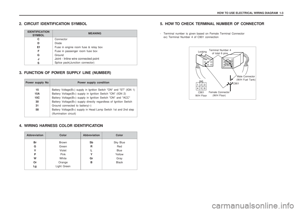
HOW TO USE ELECTRICAL WIRING DIAGRAM 1-3
Connector DiodeFuse in engine room fuse & relay box Fuse in passenger room fuse box Ground Joint - Inline wire connected point Splice pack(Junction connector)
C D
Ef F
G J
S
2. CIRCUIT IDENTIFICATION SYMBOL
3. FUNCTION OF POWER SUPPLY LINE (NUMBER)
IDENTIFICATION SYMBOL MEANING
Power supply No Power supply condition
Battery Voltage(B+) supply in Ignition Switch "ON" and "ST" (IGN 1)
Battery Voltage(B+) supply in Ignition Switch "ON" (IGN 2) Battery Voltage(B+) supply in Ignition Switch "ON" and "ACC"Battery Voltage(B+) supply directly regardless of Ignition Switch Ground connected to battery(
–)
Battery Voltage(B+) supply in Head Lamp Switch 1st and 2nd step
(Illumination circuit)
15
15A 15C
30 31 58
Abbreviation Color
BrownGreen Violet Pink
White
Orange
Light Green
Br
GV P
W
Or
LgAbbreviation Color
Sky BlueRed
Blue
Yellow
Gray
Black
Sb
RL Y
Gr B
4. WIRING HARNESS COLOR IDENTIFICATION 5. HOW TO CHECK
TERMINAL NUMBER OF CONNECTOR
- Terminal number is given based on Female Terminal Connector ex) Terminal Number 4 of C901 connection
Locking Terminal Number 4
of total 6 pins
Male Connector
(W/H Fuel Tank)
4 C901
Female Connector (W/H Floor)
C901
W/H Floor 13
2
46 5