ESP SSANGYONG MUSSO 2003 Owner's Manual
[x] Cancel search | Manufacturer: SSANGYONG, Model Year: 2003, Model line: MUSSO, Model: SSANGYONG MUSSO 2003Pages: 1574, PDF Size: 26.41 MB
Page 1099 of 1574
5D2-10 TRANSFER CASE (TOD) Electric Shift System Operation
The Electric Shift System is responsible for changing the Transfer Case gear ratio by controlling the electric shift
motor. The TCCU monitors the 4H/4L switch, neutral switch, speed sensors, position encoder, and ignition switch. A range change is initiated when
1. The 4H/4L Switch is changed from 4H to 4L or from 4L to 4H.
2. The motor position (as indicated by the position encoder) does not match the 4H/4L Switch immediately after theignition is turned on.
1. Shift Criteria When a range change is initiated a Diagnostic Test will be completed on the motor, speed sensors, and position
encoder. If the Diagnostic Test fails, the shift will not be attempted. If all components are operating properly, theTCCU will attempt a range change after the following shift criteria are met:
a. The transmission is in neutral for 2 seconds after the shift is requested.
b. Both propshaft speeds are below 87 rpm (2580 pulses/minute).
If the transmission is taken out of neutral before 2 seconds has elapsed, or either propshaft speed increases above the limit, the shift will be suspended and the 4L Indicator will continue to blink until the criteria are met again or the 4H/4L Switch is returned to the original position.
2. Range Change When the shift criteria are met, the motor is rotated in the appropriate direction (as determined by the selectorswitch) until one of the following occurs:
a. The motor reaches its destination.
b. The motor is on for 5 seconds without reaching its destination. The shift has failed and the TCCU will respond as default mode.
c. A fault occurs with either the motor or position encoder. Refer to the diagnosis requirement.
When the motor is energized, the Ignition, 4H/4L Switch, propshaft speeds, and transmission neutral inputs are ignored.
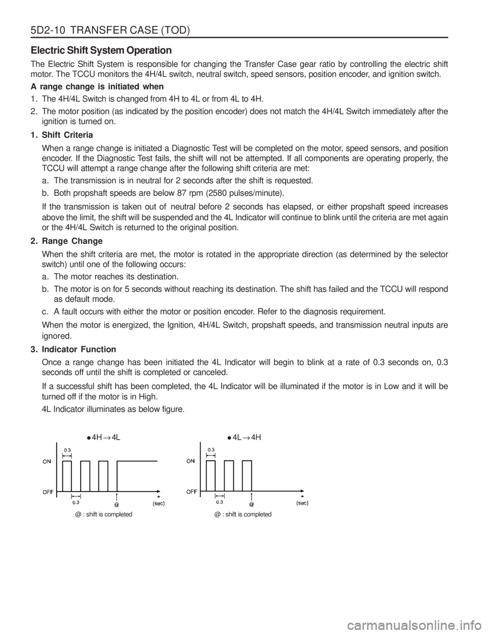
3. Indicator Function Once a range change has been initiated the 4L Indicator will begin to blink at a rate of 0.3 seconds on, 0.3 seconds off until the shift is completed or canceled.
If a successful shift has been completed, the 4L Indicator will be illuminated if the motor is in Low and it will be turned off if the motor is in High. 4L Indicator illuminates as below figure.
4H
� 4L
@ : shift is completed
4L
� 4H
@ : shift is completed
Page 1100 of 1574
TRANSFER CASE (TOD) 5D2-11
4. Electric Shift Default ModeIf the motor fails to reach its destination, the TCCU will attempt the following (in order):
a. The TCCU will wait 3 seconds then attempt the shift again.
b. If the second attempt to reach the destination fails the TCCU will wait 3 seconds then attempt to rotate the motor back to the original position. If successful, all future shifts will be inhibited until the Ignition is cycled.
c. If the attempt to return to the original position fails, the TCCU will wait 3 seconds then attempt to rotate the motor to the original position again. If the second attempt to return to the original position is successful, the “4WD CHECK ” lamp will be illuminated, and all future shifts will be inhibited until the Ignition is cycled.
d. If the second attempt to return to the original position fails the motor will be turned off, the “4WD CHECK ” lamp
will be illuminated, and all future shifts will be inhibited until the Ignition is cycled.
TOD TM
System Operation
The TOD TM
System is responsible for distributing torque between the front and rear axles. The TCCU monitors the
propshaft speeds, operating range (High/Low), and ABS activity and then applies a calculated amount of torque tothe front axle by Pulse Width Modulating the current applied to the EMC.
1. Touch-off Torque
The minimum EMC Duty Cycle is based on the vehicle speed and throttle positionThe TCCU receives the TPS signal from the following sources:On vehicles equipped with CAN, the TCCU receives the TPS signal from the CAN bus.
2. When Slip Detection
The TCCU continuously monitors the front and rear propshaft speeds to detect wheel slip.
3. Wheel Slip Control When wheel slip is detected the TCCU controls the EMC duty cycle as necessary until the wheel slip is reduced
below the allowable limit. The EMC Duty Cycle will then be reduced to the Touch-Off value.
4. Brake/ABS Strategy When the ABS System is active, the EMC Duty Cycle is set to a fixed duty cycle (30%) to aid in braking without counteracting the ABS System.
5. 4L Strategy When the system is operating in 4L, the TCCU continues TOD TM
(operation provided that the propshaft speed is
below 175 rpm (5220 pulses/minute)). When the speed increases above 175 rpm, the EMC Duty Cycle is set tothe maximum value (88%) which applies the maximum available torque to the front axle.
Page 1104 of 1574
TRANSFER CASE (TOD) 5D2-15
DIAGNOSIS
While the TCCU is active it periodically monitors its inputs and outputs. If a fault is detected the “4WD CHECK ” lamp
is illuminated and a fault code is stored in the TCCU memory.
When requested, fault codes are downloaded to a diagnostic connector (K-line) serial communications using SCAN- 100. DIAGNOSTIC TESTS 1.TCCU Internal Function
When the Ignition is turned on the TCCU tests its ROM and RAM. If there is a fault, the TCCU immediately resets itself and re-tests the ROM and RAM. If the fault persists the TCCU continues to reset and re-test until the fault is corrected or the ignition is turned off. All TCCU functions are inhibited until the fault is corrected. The “4WD
CHECK ” lamp is not illuminated if there is a ROM or RAM fault.
If the ROM/RAM passes the EEPROM memory is tested. If there is a fault the “4WD CHECK ” lamp is illuminated
and the TCCU continues to operate using the default calibration data stored in ROM. Fault codes are not storedwhen there is an EEPROM fault.
An EEPROM fault can only be cleared by cycling ignition off-on.
2.Shift Motor Assembly Test If the TCCU detects a shift motor or position encoder fault continuously for one second the ‘4WD CHECK ” lamp is
turned on and the appropriate fault code is stored in memory.
a. A shift motor fault when the motor is off is defined as follows:
Motor H-L shorted to GroundMotor L-H shorted to GroundMotor open circuit
b. A shift motor fault when the motor is energized is defined as follows: Motor H-L shorted to GroundMotor L-H shorted to GroundMotor H-L shorted to Motor L-H Motor open circuit
c. A position encoder fault is defined as follows: Any position code which does not correspond to the valid 9 codes. A short to ground on any of the encoder lines.
d. If no shifts are in progress when a failure occurs the TCCU will not respond to any shift commands.
e. If a shift command has been received, but not acted upon when a failure occurs the TCCU will cancel the command and not respond to any subsequent shift commands.
f. If a shift command is in progress when an invalid position code is confirmed it will be halted and the TCCU will turn the motor toward the high position. Afterwards the TCCU will not respond to any shift commands.
Page 1105 of 1574
5D2-16 TRANSFER CASE (TOD)g. If the shift motor/position encoder assembly failure (other than a motor failure which occurs when the motor isenergized) recovers continuously for one second the TCCU will function normally. The “4WD CHECK ” lamp is
turned off but the fault code will remain in memory.
h. A motor failure (i.e. open or short circuit) which occurs when the motor is energized can only be cleared by cycling the ignition off-on.
3. Front Speed Sensor Test If a Front Speed Sensor fault is detected continuously for 0.5 second the “4WD CHECK ” lamp is illuminated. The
TCCU then responds as follows:
a. If the system is in High Range the TCCU uses the Rear Speed Sensor to determine the EMC Touch Off level and wheel slip control is suspended.
b. If the system is in Low Range, the EMC Duty Cycle is set to maximum (independent of vehicle speed) until the system is shifted out of 4L.
c. All Electric Shift activity is halted until the Ignition is cycled. If a shift is in progress it will be completed.
If the Front Speed Sensor recovers continuously for O.5 second the TCCU will function normally. The “4WD
CHECK ” lamp is turned off but the fault code will remain in memory.
4. Rear Speed Sensor Test If a Rear Speed Sensor fault is detected continuously for 0.5 second the “4WD CHECK ” lamp is illuminated. The
TCCU then responds as follows:
a. If the system is in High Range the TCCU uses the Front Speed Sensor to determine the EMC Touch Off level and wheel slip control is suspended.
b. If the system is in Low Range, the EMC Duty Cycle is set to maximum (independent of vehicle speed) until the system is shifted out of 4L.
c. All Electric Shift activity is halted until the Ignition is cycled. If a shift is in progress it will be completed.
If the Rear Speed Sensor recovers continuously for 0.5 second the TCCU will function normally. The “4WD
CHECK ” lamp is turned off but the fault code will remain in memory.
5. Both Speed Sensor Faulty If both the Front and Rear Speed Sensors are faulty continuously for 0.5 seconds the “4WD CHECK ” lamp is
illuminated. The TCCU then responds as follows:
a. If the system is in High Range the TCCU sets the EMC Touch Off level based on a vehicle speed of 0 and wheel slip control is suspended.
b. If the system is in Low Range, the EMC Duty Cycle is set to maximum until the system is shifted out of 4L.
c. All Electric Shift activity is halted until the Ignition is cycled. If a shift is in progress it will be completed.
If both Speed Sensors recover continuously for 0.5 second the TCCU will function normally. The “4WD CHECK ”
lamp is turned off but the fault code will remain in memory.
6. EMC Test The EMC is tested for open circuit or short circuit to ground. If a fault is detected continuously for 0.8 second the “4WD CHECK ” lamp is turned on and all TOD TM
activity is halted.
If the EMC recovers continuously for 0.8 second the TCCU will function normally. The “4WD CHECK ” lamp is
turned off but the fault code will remain in memory.
Page 1113 of 1574

5D2-24 TRANSFER CASE (TOD)
Ye sNo
B4
B5
Ye s
No
B6 4.75-5.25Vdc
Ye s
No
B7 0.3-0.9Vdc 4.6-4.9Vdc
Ye s
No
4.6-4.9Vdc0.3-0.9Vdc Ye s
No
Test Stage / Contents
Result
Stage T est Contents and Procedure Specified Value
/Yes/No Countermeasure
Check CAN communication line by diagnosis of E/G ECU.
1. Diagnose E/G ECU with SCANNER.
2. Does it display on fault code
“27 ” ?
Check power supply and signal output on throttle valve position sensor (potentiometer) 1,2.
1. Diagnose E/G ECU with SCANNER. - Fault codes : 104, 105, 108, 109, 119, 185 Does it display on above code ?
Check power supply (5V) of throttle valve position sensor.
1. Ignition “ON ”
2. Measure voltage between pin 112(+) and 84(-) keeping coupling connection status using multi - tester.
- Specified value
- Measured value is within specified range ?
Check output signal from throttle position sensor 1 and 2.
1. Keep E/G idle status.
2. Measure output voltage between pin 87 (+) and 84 (-) keeping E/G ECU coupling connection status using multi-
tester. (potentiometer 1)
- Specified value min. acc. Pedal max. acc. Pedal
- Measured value is within specified range ?
3. Measure output voltage between pin 85 (+) and 84 (-) keeping E/G ECU coupling connection status using multi-
tester. (potentiometer 2)
- Specified value min. acc. Pedal
max. acc. Pedal
- Measured value is within specified range ? Replace TOD control unit Replace throttle bodyactuator or check cable
Perform B1, B2, B3 stagesPerform B5 stage Perform B6 stage Replace TOD control unit or perform A1- A5 stages Perform B7 stage Replace E/G ECU or perform B1-2 stage after checking cable. Perform B7-3 stage Replace throttle body actuator or check cable.
Page 1122 of 1574
TRANSFER CASE (TOD) 5D2-33
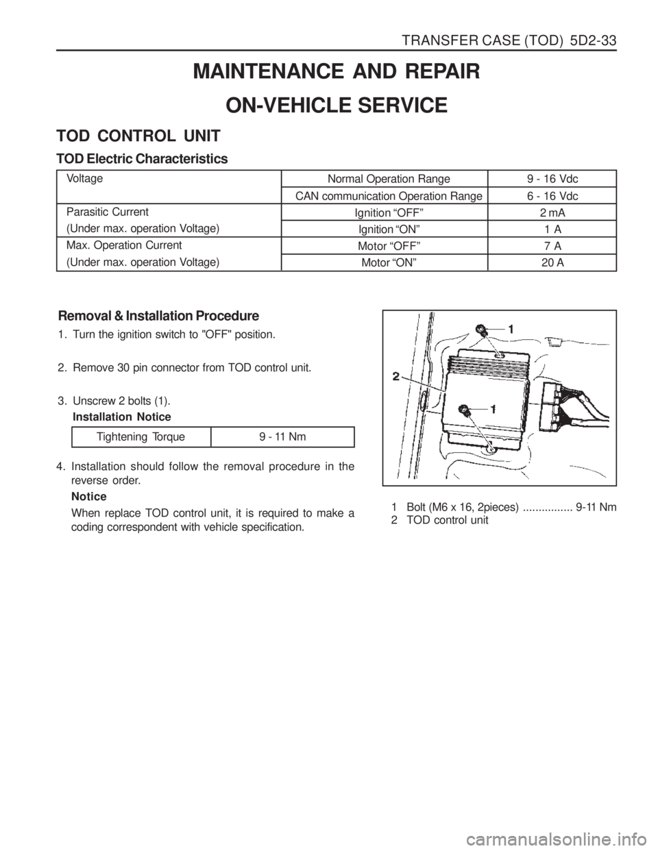
9 - 16 Vdc 6 - 16 Vdc2 mA1 A 7 A
20 A
Removal & Installation Procedure
1. Turn the ignition switch to "OFF" position.
2. Remove 30 pin connector from TOD control unit.
3. Unscrew 2 bolts (1). Installation Notice
1 Bolt (M6 x 16, 2pieces)................ 9-11 Nm
2 TOD control unit
MAINTENANCE AND REPAIR
ON-VEHICLE SERVICE
TOD CONTROL UNIT TOD Electric CharacteristicsVoltage Parasitic Current
(Under max. operation Voltage)Max. Operation Current
(Under max. operation Voltage) Normal Operation Range
CAN communication Operation Range Ignition “OFF ”
Ignition “ON ”
Motor “OFF ”
Motor “ON ”
4. Installation should follow the removal procedure in the
reverse order. Notice When replace TOD control unit, it is required to make a coding correspondent with vehicle specification.
Tightening Torque 9 - 11 Nm