air condition SSANGYONG MUSSO 2003 Workshop Manual
[x] Cancel search | Manufacturer: SSANGYONG, Model Year: 2003, Model line: MUSSO, Model: SSANGYONG MUSSO 2003Pages: 1574, PDF Size: 26.41 MB
Page 1187 of 1574

SUPPLEMENTAL RESTRAINT SYSTEM(SRS) 8B-7
DIAGNOSIS
DESCRIPTION Air bag control unit continuously controls system function as follows during ignition ON or driving.
- Recognition of collision
- Internal diagnosis
- External diagnosisIf recognize or detect defects, warning lamp will turn on. If there is danger of improper deployment, the system will enter overall shutdown status and the air bag will not inflate. Air bag control unit will store detected internal and external defects in the EEPROM. System Control
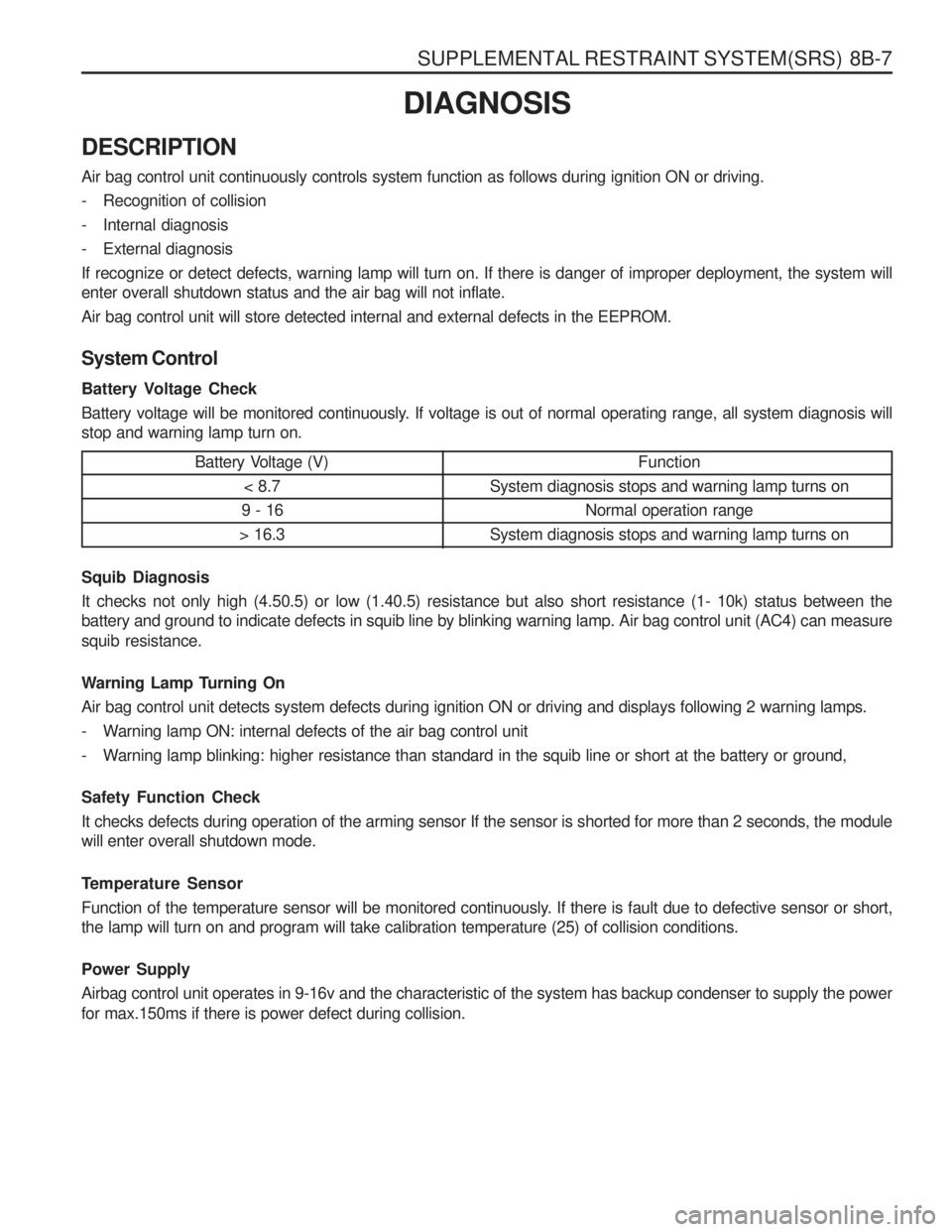
Battery Voltage Check
Battery voltage will be monitored continuously. If voltage is out of normal operating range, all system diagnosis will stop and warning lamp turn on. Battery Voltage (V)< 8.7
9 - 16
> 16.3
Function
System diagnosis stops and warning lamp turns on Normal operation range
System diagnosis stops and warning lamp turns on
Squib Diagnosis It checks not only high (4.50.5) or low (1.40.5) resistance but also short resistance (1- 10k) status between the battery and ground to indicate defects in squib line by blinking warning lamp. Air bag control unit (AC4) can measure squib resistance.
Warning Lamp Turning On Air bag control unit detects system defects during ignition ON or driving and displays following 2 warning lamps.
- Warning lamp ON: internal defects of the air bag control unit
- Warning lamp blinking: higher resistance than standard in the squib line or short at the battery or ground, Safety Function Check It checks defects during operation of the arming sensor If the sensor is shorted for more than 2 seconds, the module will enter overall shutdown mode.
Temperature Sensor
Function of the temperature sensor will be monitored continuously. If there is fault due to defective sensor or short, the lamp will turn on and program will take calibration temperature (25) of collision conditions. Power Supply Airbag control unit operates in 9-16v and the characteristic of the system has backup condenser to supply the power for max.150ms if there is power defect during collision.
Page 1189 of 1574

SUPPLEMENTAL RESTRAINT SYSTEM(SRS) 8B-9
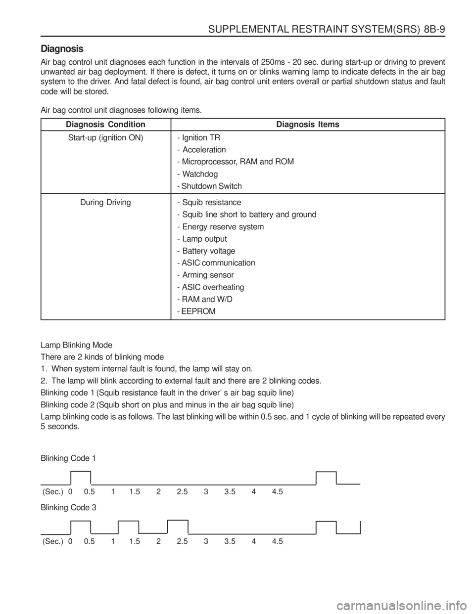
Diagnosis Air bag control unit diagnoses each function in the intervals of 250ms - 20 sec. during start-up or driving to prevent unwanted air bag deployment. If there is defect, it turns on or blinks warning lamp to indicate defects in the air bag
system to the driver. And fatal defect is found, air bag control unit enters overall or partial shutdown status and fault code will be stored. Air bag control unit diagnoses following items.- Ignition TR - Acceleration
- Microprocessor, RAM and ROM
- Watchdog - Shutdown Switch
Diagnosis Condition Diagnosis ItemsStart-up (ignition ON)
During Driving
Lamp Blinking Mode There are 2 kinds of blinking mode
1. When system internal fault is found, the lamp will stay on.
2. The lamp will blink according to external fault and there are 2 blinking codes.
Blinking code 1 (Squib resistance fault in the driver’ s air bag squib line)
Blinking code 2 (Squib short on plus and minus in the air bag squib line)Lamp blinking code is as follows. The last blinking will be within 0.5 sec. and 1 cycle of blinking will be repeated every 5 seconds.
Blinking Code 1
(Sec.) 0 0.5 1 1.5 2 2.5 3 3.5 4 4.5
Blinking Code 3
(Sec.) 0 0.5 1 1.5 2 2.5 3 3.5 4 4.5 - Squib resistance - Squib line short to battery and ground - Energy reserve system - Lamp output- Battery voltage- ASIC communication- Arming sensor - ASIC overheating - RAM and W/D- EEPROM
Page 1203 of 1574

SECTION 9A
BODY WIRING SYSTEM
Schematic and Routing Diagrams . . . . . . . . 9A-2
Power Distribution . . . . . . . . . . . . . . . . . . . . . . 9A-2
Starting & Charging (Gasoline HFM) . . . . . . . 9A-3
Starting & Charging (Diesel) . . . . . . . . . . . . . . 9A-4
Fuse Box and Relay . . . . . . . . . . . . . . . . . . . 9A-5
Location of Connectors by
Wiring Harness . . . . . . . . . . . . . . . . . . . . . 9A-7
Main . . . . . . . . . . . . . . . . . . . . . . . . . . . . . . . . 9A-7
Engine Room . . . . . . . . . . . . . . . . . . . . . . . . 9A-11
Floor . . . . . . . . . . . . . . . . . . . . . . . . . . . . . . . 9A-13
Roof . . . . . . . . . . . . . . . . . . . . . . . . . . . . . . . 9A-14
Driver's Door . . . . . . . . . . . . . . . . . . . . . . . . . 9A-15
Passenger's Door . . . . . . . . . . . . . . . . . . . . . 9A-15
TABLE OF CONTENTS
Caution: Disconnect the negative battery cable before removing or installing any electrical unit or when a tool or equipment could easily come in contact with exposed electrical terminals. Disconnecting this cable will help prevent personal injury and damage to the vehicle. The ignition must also be in LOCK unless otherwisenoted.
Rear Left Door . . . . . . . . . . . . . . . . . . . . . . . 9A-16
Rear Right Door . . . . . . . . . . . . . . . . . . . . . . 9A-16
Tail Gate . . . . . . . . . . . . . . . . . . . . . . . . . . . . 9A-17
Semi Automatic Air Conditioner . . . . . . . . . . 9A-18
Full automatic Air Conditioner . . . . . . . . . . . . 9A-19
Gasoline Engine (MSE) . . . . . . . . . . . . . . . . 9A-20
Gasoline Engine (HFM) . . . . . . . . . . . . . . . . 9A-21
Diesel Engine . . . . . . . . . . . . . . . . . . . . . . . . 9A-22
Manual Transmission . . . . . . . . . . . . . . . . . . 9A-23
Automatic Transmission (BENZ) . . . . . . . . . . 9A-24
Automatic Transmission (BTRA) . . . . . . . . . . 9A-25
Driver's Seat . . . . . . . . . . . . . . . . . . . . . . . . . 9A-26
Page 1208 of 1574

9A-6 BODY WIRING SYSTEM Engine Room Fuse (EF) and Relay Box1 Fuse (15A) : ABS, ABD
2 Fuse (20A) : Sun Roof
3 Fuse (10A) : Air Bag
4 Fuse (15A) : Audio, Clock, Out Side Mirror
5 Fuse (30A) : Cigarette lighter, Power Socket
6 Fuse (30A) : Heater
7 Fuse (15A) : Door Lock
8 Fuse (30A) : Rear Heated
9 Fuse (10A) : Audio, Buzzer, Chime, Clock
10 Fuse (30A) : Power Window
11 Fuse (10A) : Immobilizer
12 Fuse (20A) : T/C
13 Fuse (15A) : Interior Lamp
14 Fuse (15A) : Hazard Lamp
15 Fuse (15A) : Stop Lamp
16 Fuse (15A) : Turn signal Lamp, Head Lamp
17 Fuse (10A) : Back up Lamp
18 Fuse (15A) : Cluster, STICS
19 Fuse (15A) : A/T, Diagnosis
20 Fuse (15A) : Over Voltage Protection Relay (Gasolin Only)
21 Fuse (15A) : Seat Heater
22 Fuse (15A) : ECS
23 Fuse (15A) : Front Wiper & Washer
24 Fuse (10A) : Rear Wiper & Washer, A/C
25 Relay : Front Wiper 26 Relay : ABS Warning Lamp
27 Relay : Flasher Unit
28 Relay : Fuel Pump (Gasoline Only)
29 Relay : Shift Lock (A/T)
30 Relay : Clutch Interlock & Neutral
31 Relay : Sun Roof
32 Relay : A/T ‘B’ Interlock (MB A/T)
33 Relay : Power Window
34 Relay : Rear Fog Lamp
35 Relay : ECS
36 Relay : Compressor (Diesel E/G)
Condenser Fan (Gasoline E/G)
37 Relay : Condenser Fan
38 Relay : Air Conditioner
39 Fuse (10A) : Tail Lamp
40 Fuse (15A) : Head Lamp(LH)
41 Fuse (15A) : Head Lamp(RH)
42 Fuse (15A) : Front Fog Lamp
43 Fuse (10A) : Horn
44 Fuse (10A) : Compressor
45 Relay : Resistor with Diode (Gasoline E/G)
46 Relay : Front fog Lamp
47 Relay : Condenser Fan
48 Relay : Tail Lamp
49 Relay : Horn
Page 1211 of 1574

BODY WIRING SYSTEM 9A-9
44 Joint Connector.................................................... Ground
45 Door Unlock Switch
46 Front Fog Lamp Switch
47 Rear Defogger Switch
4 8 ECS Switch
49 Rear Fog Lamp Switch ........................................Rear Fog Lamp
50 Digital Clock
51 Thermo Amplifier
52 Glove Box Lamp Switch
53 Air Conditioner Wiring Connetor
54 Glove Box Lamp
55 Ground 6
56 Ground 6 ............................................................. Gasoline E/G
57 Ground 7 ............................................................. Gasoline E/G
58 Wheel Speed Sensor (FR) ..................................ABS 5.0 or ABD 5.0
59 O 2 Sensor
............................................................ E32 Gasoline E/G
60 Engine Main Wiring Connector ............................Gasoline E/G with MSE ECU
61 HFM ..................................................................... Gasoline E/G with HFM ECU
61-1 MSE ..................................................................... Gasoline E/G with MSE ECU
62 Front Door Wiring Connector (Passenger Side)
63 Front door Wiring Connector (Passenger Side)
64 Joint Connector (B+)
65 Audio
66 Audio
67 Air Bag Wiring Connector
68 Chime Bell
6 9 Buzzer
70 Kick Down Switch ................................................. Automatic Transmission
71 Diode 2 ................................................................ Manual Transmission
72 Ground 3
73 Ground 4
74 Front Cigarette Lighter
75 Diode 3 ................................................................ Automatic Transmission, MB
76 S/E Mode Selector Switch ....................................Automatic Transmission
76-1 Mode Switch ........................................................ Automatic Transmission
77 “B” Position Switch .............................................. Automatic Transmission
78 “P” Position Switch .............................................. Automatic Transmission
79 Shift Lock Solenoid Valve .....................................Automatic Transmission
8 0 TCCU
81 Ground 5 ............................................................. Gasoline E/G
81-1 Ground 7 ............................................................. Diesel E/G
82 Seat Extension Wiring Connector
83 Transmission Extension Wiring Connector ...........E23 & E32 Gasoline E/G with Manual Transmission
83-1 T ransmission Extension Wiring Connector ...........Diesel E/G with MB A/T
84 Transmission Extension Wiring Connector ...........Gasoline E/G with Manual Transmission
84-1 T ransmission Extension Wiring Connector ...........Diesel E/G with Manual Transmission or BTRE A/T
85 Transmission Extension Wiring Connector ...........E23 & E32 Gasoline E/G with A/T
85-1 T ransmission Extension Wiring Connector ...........Diesel E/G with BTRE A/T
86 Transfer Case Motor
87 Transfer Case Motor
88 Vehicle Speed Sensor
89 Fuel Gauge
90 Acceleration Sensor ............................................. ABS 5.0
91 Seat Belt Switch (Passenger)
92 Seat Heater Switch
93 Head Lamp Leveling Device Switch .....................Leveling Device
Page 1213 of 1574

BODY WIRING SYSTEM 9A-11
ENGINE ROOM1 Engine Room Relay Box
1.1 Main Wiring Connector
1.2 Main Wiring Connector
1.3 Main Wiring Connector ........................................Gasoline E/G
1.4 Joint
1.5 Compressor, Condenser Fan Relay .....................Diesel E/G
1.6 Condenser Fan Relay 2
1.7 Air Conditioner Relay
1.8 Resistor with Diode .............................................. Gasoline E/G
1.9 Front Fog Lamp Relay
1.10 Condenser Fan Relay 1
1.11 Tail Lamp Relay
1.12 Horn Relay
2 Octane Selector ................................................... Gasoline E/G with HFM
3 Preheating Unit .................................................... Diesel E/G
4 Preheating Timer Unit .......................................... Diesel E/G
5 ECS Main Wiring Connector ................................ ECS
6 Brake Leveling Fluid Sensor
7 ABD Main Wiring Connector ................................ABD 5.0
7 - 1 ABS Main Wiring Connector ................................ABD 5.0
8 ABD main Wiring Connector ................................ABD 5.0
9 Engine Temperature Sensor ................................Diesel E/G
10 ABS 5.0 ECU ....................................................... ABS 5.0
10-1 ABD 5.0 Modulator ............................................... ABD 5.0
11 Front Washer Motor ............................................. Diesel E/G
12 Head Lamp Relay
13 Compressor ......................................................... Air Conditioner
14 Wheel Speed Sensor ........................................... ABS 5.0 or ABD 5.0
Page 1214 of 1574

9A-12 BODY WIRING SYSTEM
15 LH Damper........................................................... ECS
16 Ground 1
17 Ground 2
18 Locking Hub Solenoid
19 Condenser Fan Relay .........................................Gasoline E/G
20 LH Position Lamp
21 LH Head Lamp
22 LH Head Lamp Leveling Device ...........................Leveling Device
23 Thermo Switch 2 .................................................. Gasoline E/G with HFM
24 Thermo Switch 3 .................................................. Gasoline E/G with HFM & Air Conditioner
25 LH Front Fog Lamp
26 LH Horn ............................................................... Black Out Driving Lamp (Domestic)
27 Condenser Fan Motor .........................................Diesel E/G
28 Black Out Driving Lamp .......................................Black Out Driving Lamp (Domestic)
29 LH Horn ............................................................... Leveling Device
30 LH Condenser Fan Motor ....................................Gasoline E/G with Air Conditioner
31 Thermo Switch 1 .................................................. Diesel E/G or Gasoline E/G with HFM
32 Resistor ............................................................... Gasoline E/G with Air Conditioner
33 Thermo Switch 4 .................................................. Gasoline E/G with HFM & Air Conditioner
34 Ambient Censor ................................................... Air Conditioner
35 RH Condenser Fan Motor ....................................Gasoline E/G
36 RH Horn
37 RH Front Fog Lamp
38 RH Position Lamp
39 RH Head Lamlp
40 RH Head Lamp Leveling Device ..........................Leveling Device
41 Wheeling Sensor ................................................. ECS
42 Wheel Speed Sensor (FR) ..................................ABS 5.0, 5.3 or ABD 5.0, 5.3
43 RH Damper .......................................................... ECS
44 Alternator Extension Connector ...........................Gasoline E/G
45 Alternator ............................................................. Gasoline E/G
46 Alternator Extension Joint box ..............................Diesel E/G
47 Alternator Extension Connector ...........................Diesel E/G
48 Ground 3
49 Fusible Link Box ................................................... Gasoline E/G
49-1 Fusible Link Box ................................................... Diesel E/G
50 Receiver Dryer ..................................................... Gasoline E/G with Air Conditioner
50-1 Receiver Dryer ..................................................... Diesel E/G with Air Conditioner
51 Hood Switch ......................................................... Diesel E/G with Black Out Driving Lamp
52 Front Washer Motor ............................................. Gasoline E/G
53 Main Wiring Connector
Page 1220 of 1574

9A-18 BODY WIRING SYSTEM
SEMI AUTOMATIC AIR CONDITIONER1 Main Connector
2 Air Conditioner Relay 2
3 LO Relay
4 ML Relay
5 MH Relay
6 HI Relay
7 Intake Actuator
8 Blower Motor
9 Resistor
10 Diode 11 Amplifier
1 2 Amplifier 13 Temp Actuator
14 Blower Relay
15 Water Temperature Sensor
16 Air Conditioner Switch
17 Fan Switch (Auto)
18 PTC
19 Control
20 Mode Switch
21 In Car Sensor
22 Sun Sensor
23 Mode Actuator
Page 1221 of 1574

BODY WIRING SYSTEM 9A-19
FULL AUTOMATIC AIR CONDITIONER1 Main Connector
2 Intake Actuator
3 Blower Relay
4 HI Relay
5 Power TR
6 Water Temperature Sensor
7 Temp Actuator 8 Blower Relay
9 Control (A)
10 Control (B) 11 Sun Sensor
12 Mode Actuator
13 In Car Sensor
Page 1315 of 1574

MUSSO-SPORTS 1A-3
SUPPLEMENT
HUBER EGR
SYSTEM DESCRIPTION The following chart shows the relationship between the input and the output in Huber EGR control unit. Compared to traditional system that only operates theEGR valve with RPM sensor and Micro switch, the HuberEGR control unit bring big differences that of traditionalsystem on the functions.
Input Signal
RPM sensor (CPS)
EGR valve lift sensor
Throttle position sensor (TPS) - M/T
Shift lever position
Throttle position sensor (TPS)
Vehicle speed sensor(VSS) Basic input signal for EGR operation Engine cold or hot signal
Position signal of EGR valve that is triggered by vacuum modulator 1 Transfer the engine load signal to the control unit directly (manual transmission)
TCU (A/T)
EGR
Control
Unit
Coolant temperature sensor (CTS)
Solenoid valve (Control forvacuum modulator 2)
If the control unit determines it is in no-load sharp accel- eration mode after analyzing the input signals, this conver- sion type switch reduces the fuel consumption by cutting off the intake air pressure from
fuel injection ALDA and gen- erating the vacuum pressure. In no-load sharp acceleration
mode, Duty Control ( continu- ous precise control) is acti- vated according to the varia- tions of the input signals when the solenoid valve generates the vacuum pressure in ALDA.
Vacuum modulator 2
The opening value of the modulator is precisely con- trolled by input signals and programmed MAP, and the opening value of EGR valve is also changed by the varia- tions of vacuum pressure to EGR valve. The changed opening value is transferred to the control unit as input signal.
Vacuum modulator 1
TCU in automatic transmission equipped vehicle transfers the information such as driving conditions and speeds into the EGR control unit. EGR control unit uses the shift lever position and vehicle speed as important information for operating the solenoid valve during no-load sharp acceleration mode. In manual transmission, the signal of vehicle speed is transferred into the EGR control unit directly.
Clutch switch
In manual transmission, the clutch switch is the one of core elements to determine driving condition. Output Signal
EGR Control Unit