SSANGYONG MUSSO 2003 Service Manual
MUSSO 2003
SSANGYONG
SSANGYONG
https://www.carmanualsonline.info/img/67/57511/w960_57511-0.png
SSANGYONG MUSSO 2003 Service Manual
Page 688 of 1574
OM600 ENGINE INTAKE & EXHAUST 1G3-5
INTAKE AND EXHAUST MANIFOLD
1 Nut .................................................22.5-27.5 Nm
2 Washer
3 Support Assembly Bar
4 Nut ................................................. 22.5-27.5 Nm
5 Exhaust Manifold Assembly
6 Exhaust Gasket 7 Stud Bolt
.......................................... 9.9-12.1 Nm
8 Bolt (M8) ........................................ 22.5-27.5 Nm
9 Intake Duct
10 Intake Duct Gasket
11 Intake Manifold
12 Intake Gasket
Page 689 of 1574
1G3-6 OM600 ENGINE INTAKE & EXHAUST Exhaust Line
1 Heat Protector Assembly
2 Heat Protector Floor
3 Exhaust Front Pipe Assembly
4 Ring
5 Exhaust Rear Pipe Assembly6 Muffler
7 Mounting
8 Heat Protector Front Floor
9 Tail Exhaust Pipe Assembly
Page 690 of 1574
1F3-42 OM600 ENGINE CONTROLS
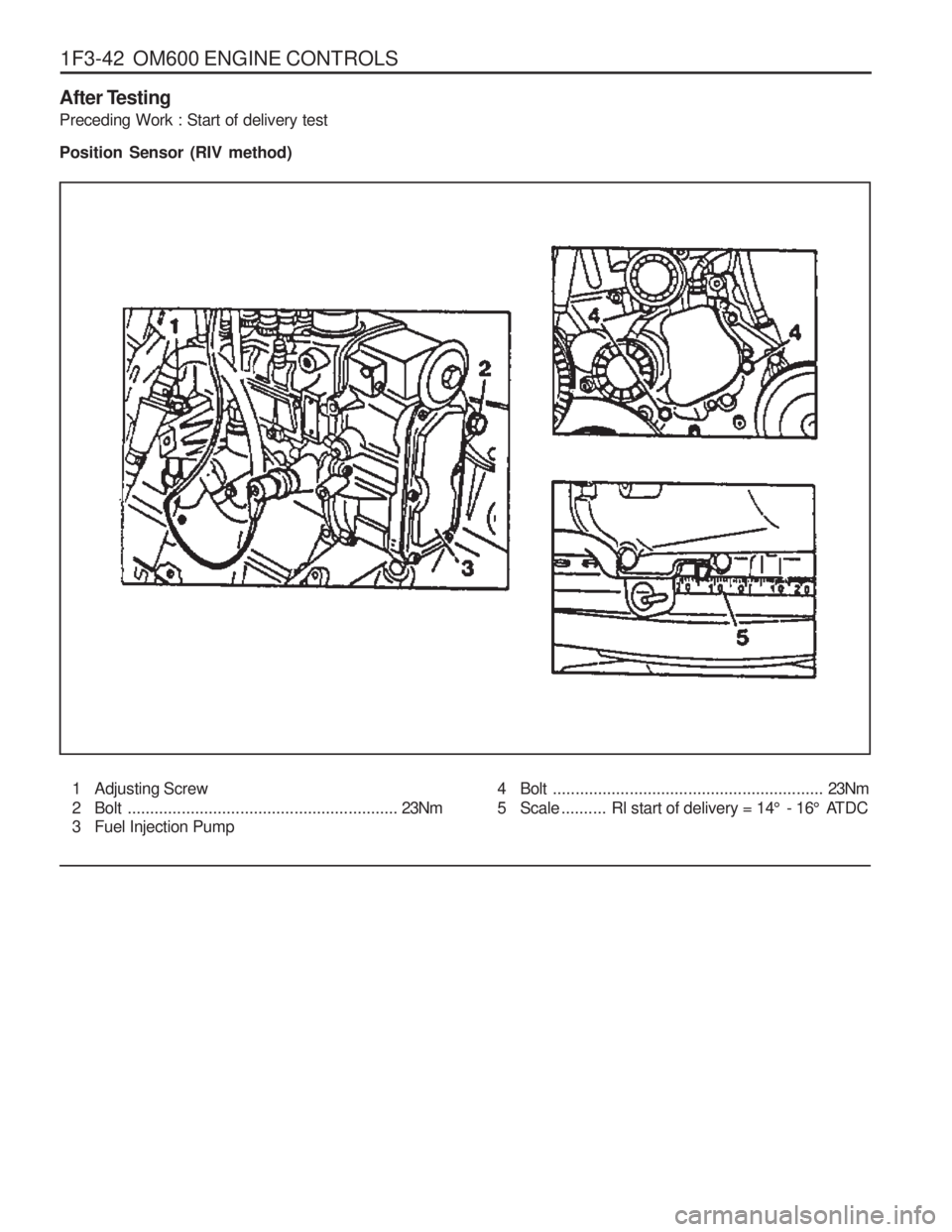
After Testing Preceding Work : Start of delivery test Position Sensor (RIV method)
1 Adjusting Screw
2 Bolt ............................................................ 23Nm
3 Fuel Injection Pump 4 Bolt
............................................................ 23Nm
5 Scale .......... Rl start of delivery = 14 ° - 16 ° ATDC
Page 691 of 1574
OM600 ENGINE INTAKE & EXHAUST 1G3-7
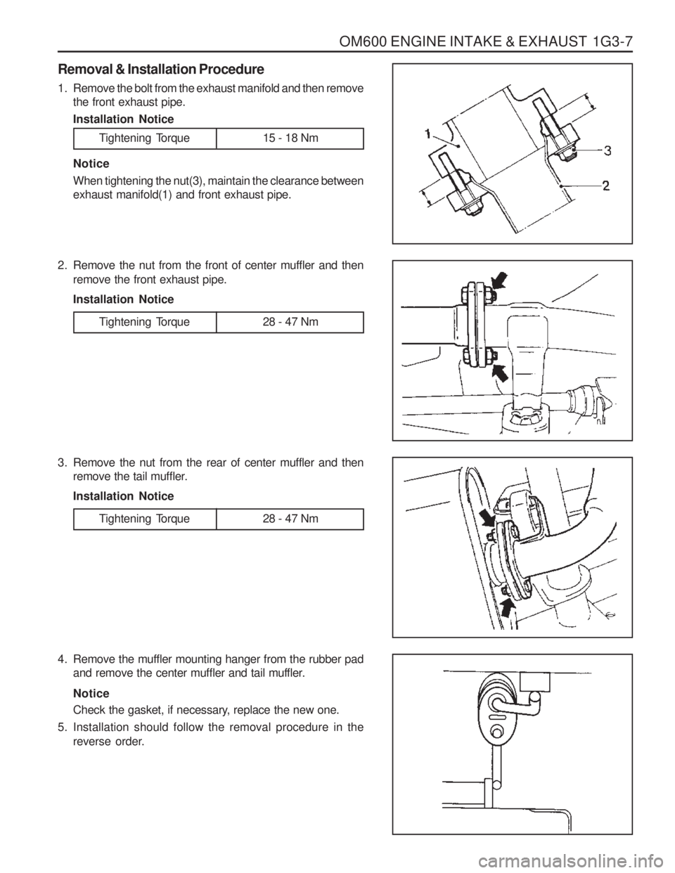
Removal & Installation Procedure
1. Remove the bolt from the exhaust manifold and then removethe front exhaust pipe. Installation Notice
Tightening Torque 15 - 18 Nm
Notice When tightening the nut(3), maintain the clearance between exhaust manifold(1) and front exhaust pipe.
2. Remove the nut from the front of center muffler and then remove the front exhaust pipe. Installation Notice
3. Remove the nut from the rear of center muffler and then remove the tail muffler.Installation Notice
4. Remove the muffler mounting hanger from the rubber pad and remove the center muffler and tail muffler. Notice
Check the gasket, if necessary, replace the new one.
5. Installation should follow the removal procedure in the reverse order.
Tightening Torque 28 - 47 Nm
Tightening Torque 28 - 47 Nm
Page 692 of 1574
1G3-8 OM600 ENGINE INTAKE & EXHAUST
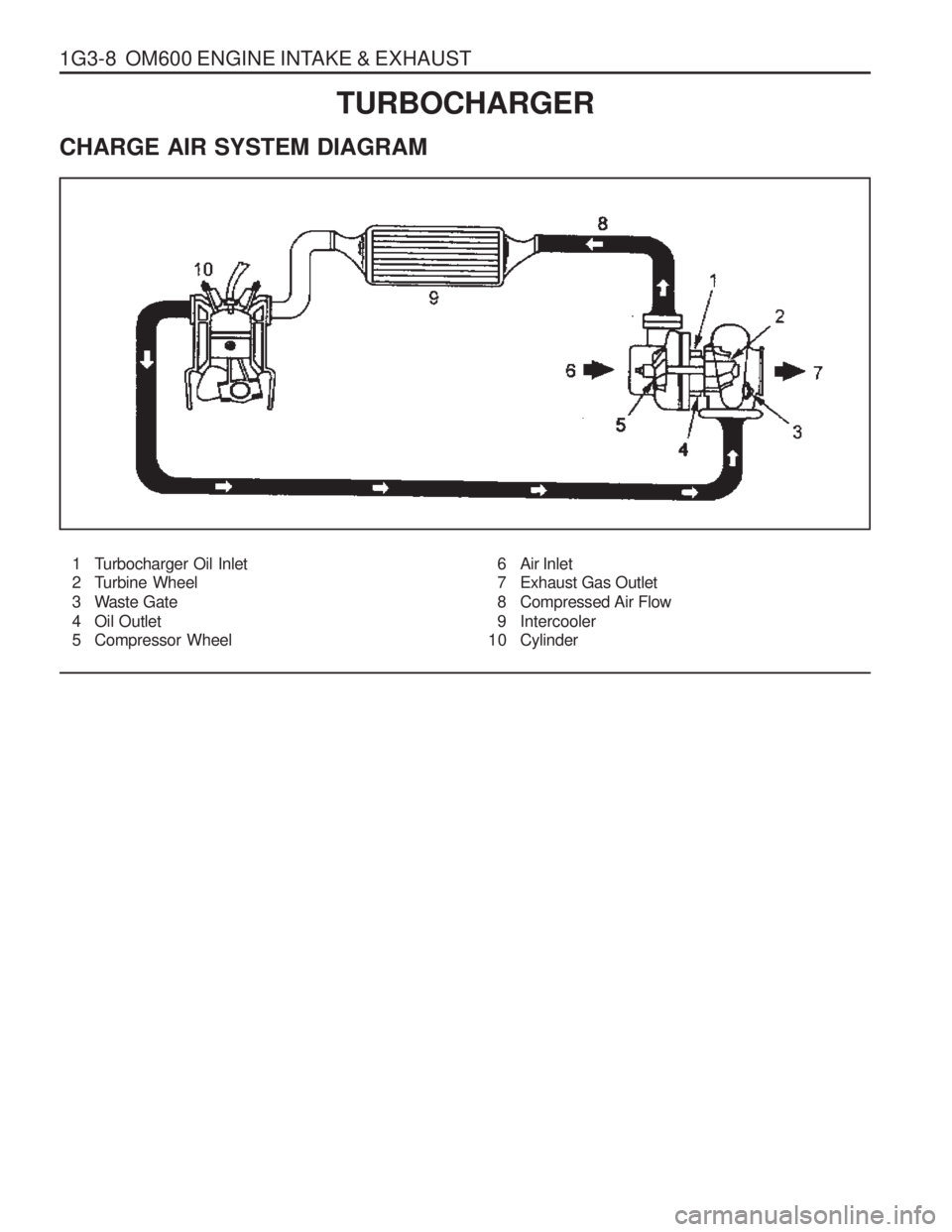
1 Turbocharger Oil Inlet
2 Turbine Wheel
3 Waste Gate
4 Oil Outlet
5 Compressor Wheel6 Air Inlet
7 Exhaust Gas Outlet
8 Compressed Air Flow
9 Intercooler
10 Cylinder
TURBOCHARGER
CHARGE AIR SYSTEM DIAGRAM
Page 693 of 1574
OM600 ENGINE INTAKE & EXHAUST 1G3-9
INTERCOOLER
1 Hoses
2 Pipes
3 Hoses
4 Intercooler5 Cover
6 Bolts
7 Screws
8 Bolts
Page 694 of 1574
1G3-10 OM600 ENGINE INTAKE & EXHAUST
Removal & Installation Procedure
1. Remove the hose connected to turbocharger and intakeduct.
2. Remove the protective cover.
3. Loosen the clamps and remove the pipe and hose connected to intercooler.
4. Unscrew the mounting bolts and remove the intercooler.
5. Installation should follow the removal procedure in the reverse order.
Page 695 of 1574
OM600 ENGINE INTAKE & EXHAUST 1G3-11
TURBOCHARGER ASSEMBLY
1 Oil Supply Line
2 Oil Return Line3 Nuts
4 Turbocharger
Page 696 of 1574
1G3-12 OM600 ENGINE INTAKE & EXHAUST
Removal & Installation Procedure
1. Remove the 2 hoses connected to intercooler.
2. Remove the hose(air cleaner to turbocharger) with blow byhose.
3. Disconnect the oil supply pipe.
4. Remove the oil return pipe.
5. Remove the support assembly.
6. Remove the 3 nuts(arrows).
Page 697 of 1574
OM600 ENGINE INTAKE & EXHAUST 1G3-13
7. Remove the turbocharger disconnecting the exhaust pipefrom the turbocharger.
8. Installation should follow the removal procedure in the reverse order.


