automatic transmission fluid SSANGYONG MUSSO 2003 Service Manual
[x] Cancel search | Manufacturer: SSANGYONG, Model Year: 2003, Model line: MUSSO, Model: SSANGYONG MUSSO 2003Pages: 1574, PDF Size: 26.41 MB
Page 9 of 1574
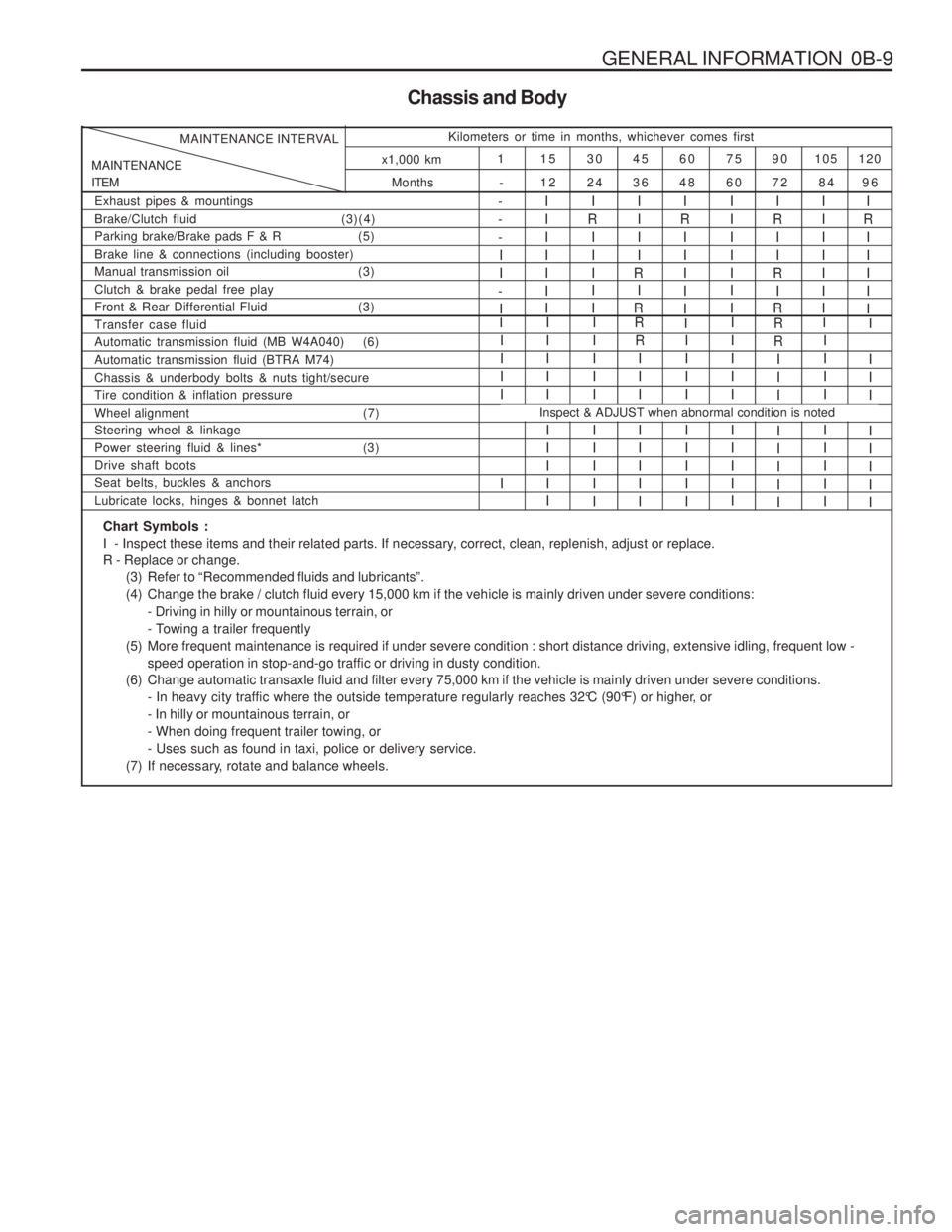
GENERAL INFORMATION 0B-9
Chassis and Body
Months
MAINTENANCE ITEM MAINTENANCE INTERVAL
Kilometers or time in months, whichever comes first
120
105
90
75
60
45
30
15
1
96
84
72
60
48
36
24
12
-
x1,000 km
Exhaust pipes & mountings Brake/Clutch fluid
(3)(4)
Parking brake/Brake pads F & R (5)Brake line & connections (including booster)
Manual transmission oil (3) Clutch & brake pedal free play
Front & Rear Differential Fluid (3)I
R
IIIII- --II
-
I IIIIII I
I
R I II I I IIII
R I
R IIIII I II
R
II
R I
R IIIIII II
R I IIII
Automatic transmission fluid (MB W4A040) (6) Automatic transmission fluid (BTRA M74)Chassis & underbody bolts & nuts tight/secure Tire condition & inflation pressure
Wheel alignment (7) Steering wheel & linkage
Power steering fluid & lines* (3)Drive shaft boots Seat belts, buckles & anchors Lubricate locks, hinges & bonnet latchIIII I I IIII I III I I IIII I IIII
R
III I IIII IIII I IIIIIIIII I III I
R R
III I IIII IIII I IIII
Transfer case fluidRII
I
Inspect & ADJUST when abnormal condition is noted
I
I II I IIII
Chart Symbols :
I - Inspect these items and their related parts. If necessary, correct, clean, replenish, adjust or replace.R - Replace or change.
(3) Refer to “Recommended fluids and lubricants”.
(4) Change the brake / clutch fluid every 15,000 km if the vehicle is mainly driven under severe conditions:- Driving in hilly or mountainous terrain, or
- Towing a trailer frequently
(5) More frequent maintenance is required if under severe condition : short distance driving, extensive idling, frequent low - speed operation in stop-and-go traffic or driving in dusty condition.
(6) Change automatic transaxle fluid and filter every 75,000 km if the vehicle is mainly driven under severe conditions. - In heavy city traffic where the outside temperature regularly reaches 32°C (90°F) or higher, or- In hilly or mountainous terrain, or- When doing frequent trailer towing, or- Uses such as found in taxi, police or delivery service.
(7) If necessary, rotate and balance wheels.
Page 11 of 1574
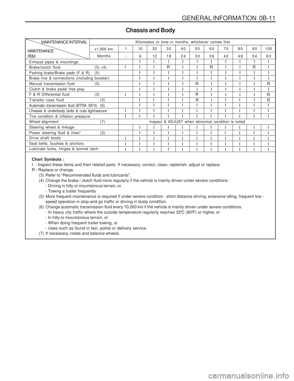
GENERAL INFORMATION 0B-11
Chassis and Body
Months -
MAINTENANCE ITEMMAINTENANCE INTERVAL
Kilometers or time in months, whichever comes first
100
90
80
70
60
50
40
30
20
10
1
60
54
48
42
36
30
24
18
12
6
x1,000 km
Exhaust pipes & mountings
Brake/clutch fluid (3) (4)
Parking brake/Brake pads (F & R) (5) Brake line & connections (including booster)
Manual transmission fluid (3)Clutch & brake pedal free play
F & R Differential fluid (3)
I I I IIIIIIIIIIIII I
R
IIIII IIIIIII IIII
R I
R I
R
IIIII IIIIIIIIIIIIII I
R
IIIII IIII
R I
R
Automatic transmission fluid (BTRA M74) (6) Chassis & underbody bolts & nuts tight/secure Tire condition & inflation pressure
Wheel alignment (7) Steering wheel & linkage
Power steering fluid & lines* (3) Drive shaft boots Seat belts, buckles & anchors Lubricate locks, hinges & bonnet latchI II I IIII III I IIII IIII I III I
I II I IIII III I IIIIIII I IIII III II II III I IIIIIII I IIII
Transfer case fluid (3)
RI R
I
I
I
I I I II IIII I IIII
Inspect & ADJUST when abnormal condition is noted
II I
Chart Symbols :
I - Inspect these items and their related parts. If necessary, correct, clean, replenish, adjust or replace.R - Replace or change.
(3) Refer to “Recommended fluids and lubricants”.
(4) Change the brake / clutch fluid more regularly if the vehicle is mainly driven under severe conditions :- Driving in hilly or mountainous terrain, or
- Towing a trailer frequently
(5) More frequent maintenance is required if under severe condition : short distance driving, extensive idling, frequent low - speed operation in stop-and-go traffic or driving in dusty condition.
(6) Change automatic transmission fluid every 70,000 km if the vehicle is mainly driven under severe conditions. - In heavy city traffic where the outside temperature regularly reaches 32°C (90°F) or higher, or- In hilly or mountainous terrain, or- When doing frequent trailer towing, or- Uses such as found in taxi, police or delivery service.
(7) If necessary, rotate and balance wheels.
Page 26 of 1574
GENERAL ENGINE INFORMATION 1A1-7
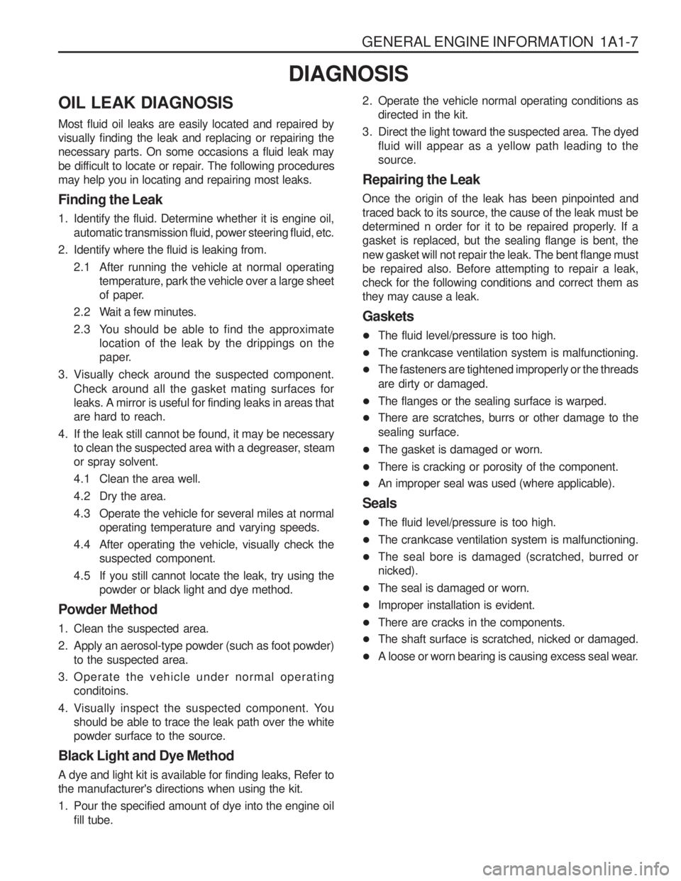
OIL LEAK DIAGNOSIS Most fluid oil leaks are easily located and repaired by visually finding the leak and replacing or repairing thenecessary parts. On some occasions a fluid leak may
be difficult to locate or repair. The following proceduresmay help you in locating and repairing most leaks. Finding the Leak
1. Identify the fluid. Determine whether it is engine oil,automatic transmission fluid, power steering fluid, etc.
2. Identify where the fluid is leaking from. 2.1 After running the vehicle at normal operating temperature, park the vehicle over a large sheet
of paper.
2.2 Wait a few minutes.
2.3 You should be able to find the approximate location of the leak by the drippings on the
paper.
3. Visually check around the suspected component. Check around all the gasket mating surfaces forleaks. A mirror is useful for finding leaks in areas thatare hard to reach.
4. If the leak still cannot be found, it may be necessary to clean the suspected area with a degreaser, steamor spray solvent.
4.1 Clean the area well.
4.2 Dry the area.
4.3 Operate the vehicle for several miles at normal operating temperature and varying speeds.
4.4 After operating the vehicle, visually check the suspected component.
4.5 If you still cannot locate the leak, try using the powder or black light and dye method.
Powder Method
1. Clean the suspected area.
2. Apply an aerosol-type powder (such as foot powder) to the suspected area.
3. Operate the vehicle under normal operating conditoins.
4. Visually inspect the suspected component. You should be able to trace the leak path over the white powder surface to the source.
Black Light and Dye Method A dye and light kit is available for finding leaks, Refer to the manufacturer's directions when using the kit.
1. Pour the specified amount of dye into the engine oil fill tube. 2. Operate the vehicle normal operating conditions as
directed in the kit.
3. Direct the light toward the suspected area. The dyed fluid will appear as a yellow path leading to the source.
Repairing the Leak Once the origin of the leak has been pinpointed and traced back to its source, the cause of the leak must be
determined n order for it to be repaired properly. If agasket is replaced, but the sealing flange is bent, the new gasket will not repair the leak. The bent flange must be repaired also. Before attempting to repair a leak,check for the following conditions and correct them asthey may cause a leak. Gaskets
� The fluid level/pressure is too high.
� The crankcase ventilation system is malfunctioning.
� The fasteners are tightened improperly or the threads are dirty or damaged.
� The flanges or the sealing surface is warped.
� There are scratches, burrs or other damage to thesealing surface.
� The gasket is damaged or worn.
� There is cracking or porosity of the component.
� An improper seal was used (where applicable).
Seals
� The fluid level/pressure is too high.
� The crankcase ventilation system is malfunctioning.
� The seal bore is damaged (scratched, burred or nicked).
� The seal is damaged or worn.
� Improper installation is evident.
� There are cracks in the components.
� The shaft surface is scratched, nicked or damaged.
� A loose or worn bearing is causing excess seal wear.
DIAGNOSIS
Page 281 of 1574
1B3-16 OM600 ENGINE MECHANICAL
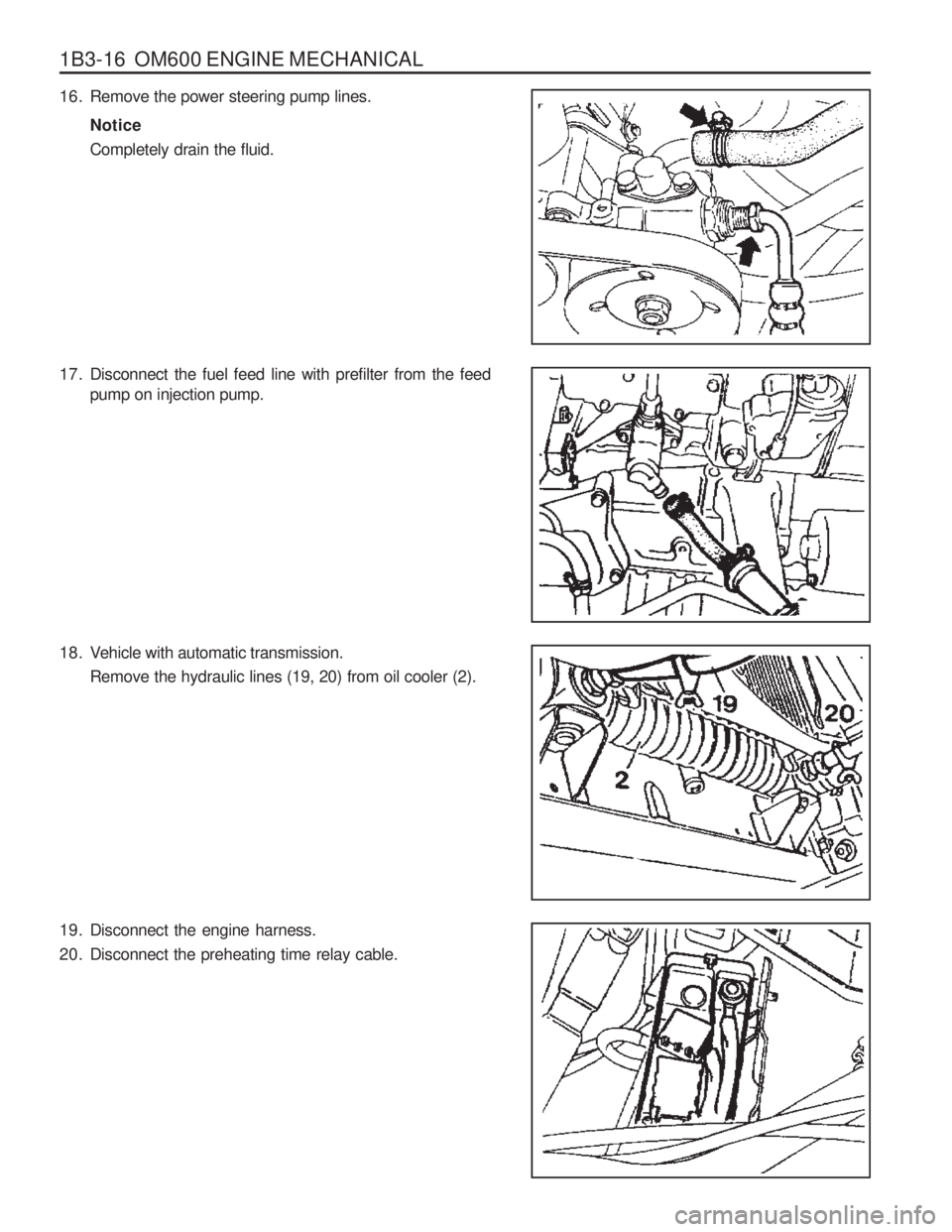
16. Remove the power steering pump lines.Notice Completely drain the fluid.
17. Disconnect the fuel feed line with prefilter from the feed pump on injection pump.
18. Vehicle with automatic transmission. Remove the hydraulic lines (19, 20) from oil cooler (2).
19. Disconnect the engine harness.
20. Disconnect the preheating time relay cable.
Page 860 of 1574
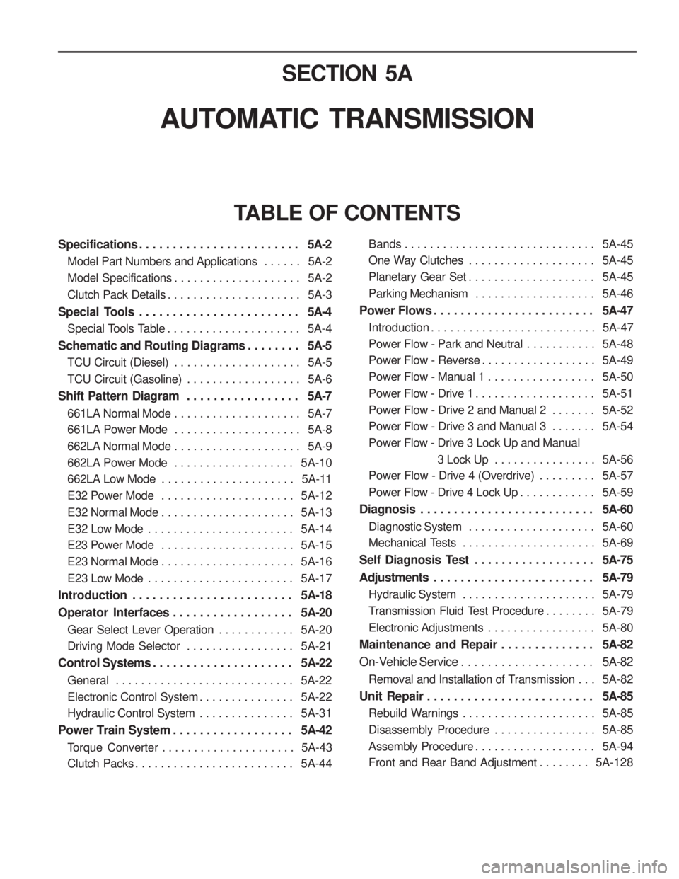
SECTION 5A
AUTOMATIC TRANSMISSION
TABLE OF CONTENTS
Specifications . . . . . . . . . . . . . . . . . . . . . . . . 5A-2
Model Part Numbers and Applications . . . . . . 5A-2
Model Specifications . . . . . . . . . . . . . . . . . . . . 5A-2
Clutch Pack Details . . . . . . . . . . . . . . . . . . . . . 5A-3
Special Tools . . . . . . . . . . . . . . . . . . . . . . . . 5A-4
Special Tools Table . . . . . . . . . . . . . . . . . . . . . 5A-4
Schematic and Routing Diagrams . . . . . . . . 5A-5
TCU Circuit (Diesel) . . . . . . . . . . . . . . . . . . . . 5A-5
TCU Circuit (Gasoline) . . . . . . . . . . . . . . . . . . 5A-6
Shift Pattern Diagram . . . . . . . . . . . . . . . . . 5A-7
661LA Normal Mode . . . . . . . . . . . . . . . . . . . . 5A-7
661LA Power Mode . . . . . . . . . . . . . . . . . . . . 5A-8
662LA Normal Mode . . . . . . . . . . . . . . . . . . . . 5A-9
662LA Power Mode . . . . . . . . . . . . . . . . . . . 5A-10
662LA Low Mode . . . . . . . . . . . . . . . . . . . . . 5A-11
E32 Power Mode . . . . . . . . . . . . . . . . . . . . . 5A-12
E32 Normal Mode . . . . . . . . . . . . . . . . . . . . . 5A-13
E32 Low Mode . . . . . . . . . . . . . . . . . . . . . . . 5A-14
E23 Power Mode . . . . . . . . . . . . . . . . . . . . . 5A-15
E23 Normal Mode . . . . . . . . . . . . . . . . . . . . . 5A-16
E23 Low Mode . . . . . . . . . . . . . . . . . . . . . . . 5A-17
Introduction . . . . . . . . . . . . . . . . . . . . . . . . 5A-18
Operator Interfaces . . . . . . . . . . . . . . . . . . 5A-20
Gear Select Lever Operation . . . . . . . . . . . . 5A-20
Driving Mode Selector . . . . . . . . . . . . . . . . . 5A-21
Control Systems . . . . . . . . . . . . . . . . . . . . . 5A-22
General . . . . . . . . . . . . . . . . . . . . . . . . . . . . 5A-22
Electronic Control System . . . . . . . . . . . . . . . 5A-22
Hydraulic Control System . . . . . . . . . . . . . . . 5A-31
Power Train System . . . . . . . . . . . . . . . . . . 5A-42
Torque Converter . . . . . . . . . . . . . . . . . . . . . 5A-43
Clutch Packs . . . . . . . . . . . . . . . . . . . . . . . . . 5A-44Bands . . . . . . . . . . . . . . . . . . . . . . . . . . . . . . 5A-45
One Way Clutches . . . . . . . . . . . . . . . . . . . .
5A-45
Planetary Gear Set . . . . . . . . . . . . . . . . . . . . 5A-45
Parking Mechanism . . . . . . . . . . . . . . . . . . . 5A-46
Power Flows . . . . . . . . . . . . . . . . . . . . . . . . 5A-47
Introduction . . . . . . . . . . . . . . . . . . . . . . . . . . 5A-47
Power Flow - Park and Neutral . . . . . . . . . . . 5A-48
Power Flow - Reverse . . . . . . . . . . . . . . . . . . 5A-49
Power Flow - Manual 1 . . . . . . . . . . . . . . . . . 5A-50
Power Flow - Drive 1 . . . . . . . . . . . . . . . . . . . 5A-51
Power Flow - Drive 2 and Manual 2 . . . . . . . 5A-52
Power Flow - Drive 3 and Manual 3 . . . . . . . 5A-54
Power Flow - Drive 3 Lock Up and Manual
3 Lock Up . . . . . . . . . . . . . . . . 5A-56
Power Flow - Drive 4 (Overdrive) . . . . . . . . . 5A-57
Power Flow - Drive 4 Lock Up . . . . . . . . . . . . 5A-59
Diagnosis . . . . . . . . . . . . . . . . . . . . . . . . . . 5A-60
Diagnostic System . . . . . . . . . . . . . . . . . . . . 5A-60
Mechanical Tests . . . . . . . . . . . . . . . . . . . . . 5A-69
Self Diagnosis Test . . . . . . . . . . . . . . . . . . 5A-75
Adjustments . . . . . . . . . . . . . . . . . . . . . . . . 5A-79
Hydraulic System . . . . . . . . . . . . . . . . . . . . . 5A-79
Transmission Fluid Test Procedure . . . . . . . . 5A-79
Electronic Adjustments . . . . . . . . . . . . . . . . . 5A-80
Maintenance and Repair . . . . . . . . . . . . . . 5A-82
On-Vehicle Service . . . . . . . . . . . . . . . . . . . . 5A-82
Removal and Installation of Transmission . . . 5A-82
Unit Repair . . . . . . . . . . . . . . . . . . . . . . . . . 5A-85
Rebuild Warnings . . . . . . . . . . . . . . . . . . . . . 5A-85
Disassembly Procedure . . . . . . . . . . . . . . . . 5A-85
Assembly Procedure . . . . . . . . . . . . . . . . . . . 5A-94
Front and Rear Band Adjustment . . . . . . . . 5A-128
Page 861 of 1574
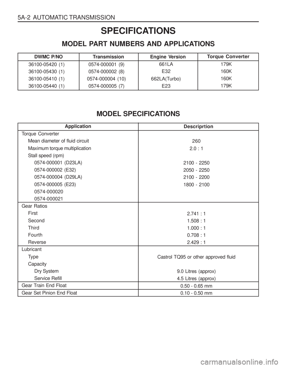
5A-2 AUTOMATIC TRANSMISSIONSPECIFICATIONS
MODEL PART NUMBERS AND APPLICATIONS
Transmission
0574-000001 (9) 0574-000002 (8)
0574-000004 (10) 0574-000005 (7) Torque Converter
179K160K160K179KEngine Version661LAE32
662LA(Turbo) E23
MODEL SPECIFICATIONS
Application
Torque Converter Mean diameter of fluid circuit Maximum torque multiplication Stall speed (rpm)0574-000001 (D23LA)0574-000002 (E32)0574-000004 (D29LA) 0574-000005 (E23) 0574-0000200574-000021
Gear Ratios First Second ThirdFourthReverse
Lubricant
TypeCapacityDry SystemService Refill
Gear Train End Float Gear Set Pinion End FloatDescriprtion
260
2.0 : 1
2100 - 2250 2050 - 22502100 - 2200 1800 - 2100
2.741 : 1 1.508 : 11.000 : 10.708 : 12.429 : 1
Castrol TQ95 or other approved fluid 9.0 Litres (approx)4.5 Litres (approx)0.50 - 0.65 mm0.10 - 0.50 mm
DWMC P/NO
36100-05420 (1)36100-05430 (1)36100-05410 (1)36100-05440 (1)
Page 901 of 1574

5A-42 AUTOMATIC TRANSMISSIONPOWER TRAIN SYSTEM
The Power Train System consists of: � A torque converter with single face lock-up clutch
� Four multi-plate clutch assemblies
� Two brake bands
� Two one-way clutches
� Planetary gearset
� Parking mechanism
A conventional six pinion Ravigneaux compound planetary gearset is used with overdrive (fourth gear) being obtained
by driving the carrier.
The cross-sectional arrangement is very modular in nature. Four main sub-assemblies are installed within the case
to complete the build. These sub-assemblies are: � Gearset-sprag-centre support
� C1 -C2-C3-C4 clutch sub-assembly
� Pump assembly
� Valve body assembly
One, or a combination of selective washers are used between the input shaft flange and the number 4 bearing to
control the transmission end float. This arrangement allows for extensive subassembly testing and simplistic finalassembly during production.
A general description of the operation of the Power Train System is detailed below. Refer to table 4.1 and figure 4.1.
First gear is engaged by applying the C2 clutch and locking the 1-2 One Way Clutch (1-2 OWC). The 1-2 shift is
accomplished by applying the B1 band and overrunning the 1-2 OWC. The 2-3 shift is accomplished by applying the
C1 clutch and releasing the B1 band. The 3-4 shift is accomplished by re-applying the B1 band and overrunning the
3-4 OWC. Reverse gear is engaged by applying the C3 clutch and the B2 band.
The C4 clutch is applied in the Manual 1,2 and 3 ranges to provide engine braking. In addition, the C4 clutch is also
applied in the Drive range for second and third gears to eliminate objectionable freewheel coasting. The B2 band is
also applied in the Manual 1 range to accomplish the low-overrun shift.
Both the front and rear servos are dual area designs to allow accurate friction element matching without the need for
secondary regulator valves. All the friction elements have been designed to provide low shift energies and high static
capacities when used with the new low static co-efficient transmission fluids. Non-asbestos friction materials are used throughout.
Gear
First
Second ThirdFourth
Reverse
Manual 1 Gear
Ratio 2.741 1.508 1.0000.7082.4282.741 C1
XX C2
X X XX X C3
X C4
X X B1
X X X B2
X X 1-2
OWC X 3-4
OWC X XX LU
CLUTCH
X*X
ELEMENTS ENGAGED
* For Certain Vehicle Applications, Refer to the Owner's Manual.
Table 4.1 - Engaged Elements vs Gear Ratios
Page 928 of 1574

AUTOMATIC TRANSMISSION 5A-69
MECHANICAL TESTS
In Vehicle Transmission Checks
Carry out the following tests before removing the transmission.� See Checking Transmission Fluid Level, Section 7.2.1.
� Check that the transmission oil is not burnt (colour and smell are correct).
� Ensure that the transmission is not in limp home mode (LHM).
� Check that the battery terminals and the earth connections are not corroded or loose.
� Check the engine stall speed is within the handbook value.
� Check that the cooler flow is not restricted.
� Check that all electrical plug connections are tight.
� Carry out a road test to confirm the symptoms, if necessary.
� Inspect the oil, ensure that there are no metal or other contaminants in the oil pan.
Diagnosing Oil Leaks
Determine the source of oil leaks by firstly cleaning down the affected area, then driving the vehicle. Inspect the seals to confirm the source of the leak. � To determine the source of a rear servo oil leak, raise the vehicle on a hoist, then carry out a reverse stall.
� To determine the source of a front servo leak, raise the vehicle on a hoist, then run the vehicle in second gear.
Troubleshooting Charts The troubleshooting charts are set out as follows: � Table 6.2.1 Drive Faults,
� Table 6.2.2 Faulty Shift Patterns.
� Table 6.2.3 Shift Quality Faults.
� Table 6.2.4 After Teardown Faults.
Table 6.2.1 - Drive Faults
Action
Check the fluid level. Top up as necessary. Inspect and clean C1/C2 feed. Reinstall/renew the ‘z’ link.
Remove, clean and re-install the PRV.
Inspect and replace as necessary.
Inspect and replace as necessary.
Inspect and replace as necessary.
Check servo adjustment or replace rear band
as necessary.
Check for failure in C3, C3 hub or C1/C2 cylin-
der. Repair as necessary.
Inspect and clean PRV.
Inspect and replace pump gears as necessary.
Inspect and repair as necessary.
Possible Cause
Insufficient auto transmission fluid.
Blocked feed in C1/C2 cylinder.
‘Z’ link displaced.
Primal regulator valve (PRV) jammed open.Overdrive shaft or input shaft seal ringsfailed. 3-4 or 1-2 one way clutch (OWC) installed backwards or failed.C2 piston broken or cracked.
Rear band or servo faulty.
Failure in C3, C3 hub or C1/C2 cylinder.Jammed primary regulator valve (PRV). Damaged/broken pump gears. Dislodged output shaft snap ring.Symptom
No Drive in D No Drive in ReverseNo engine braking
in Manual 1 Engine braking in Manual 1 is OKNo drive in Driveand Reverse
Page 931 of 1574

5A-72 AUTOMATIC TRANSMISSION
Action
Drain and fill with specified ATF.
Check that S5 is fitted correctly, or replace S5.
Inspect band apply and clutch apply regulator
springs. Refit or replace as necessary.
Inspect the ball. Refit or replace as necessary.
Inspect C4 clutch. Replace or repair as neces-
sary.
Check the alignment. ]Realign as necessary.
Inspect wave plate. Replace as necessary.
Inspect S5 and replace as necessary.
Inspect the damper spring and replace as nec-
essary.
Replace spring as necessary.
Check the clearance and adjust as necessary.
Inspect C4. Repair or replace as necessary.
Inspect piston. Repair or replace as necessary.
Inspect and adjust band as necessary. Replace the plug. Replace the spring.Replace the spring/plug.Refit the ball.
Inspect the clutch. Repair the clutch as neces-
sary. Inspect and clean C1 feed.Replace the piston.
Inspect and replace the sealing rings and/or
shaft as necessary. Inspect and replace the ball.
Inspect and replace the sealing rings and/or
shaft as necessary.
Inspect and repair the C1 clutch as necessary.Refit the valve. Replace the ball.
Possible Cause
Incorrect auto transmission fluid (ATF).
S5 faulty won, or incorrectly fitted.Band apply and clutch apply regulatorsprings misplaced. Over-run clutch (OC)/Low-1st ball misplaced.C4 clutch worn or burnt. C4 wave plate not lined up with the holes in the piston. C4 wave plate failed.S5 worn.S5 damper spring broken. Front servo belleville spring broken. Incorrect C4 pack clearance.Damaged C4 clutch.Cracked C2 piston (leaking into C4).Incorrect band adjustment Front servo plastic plug missing B1R spring broken.B1R spring/plug left out.C1/B1R ball misplaced.C1 clutch damaged. Restriction in C1 feed. C1 piston check ball jammed.
Overdrive or input shaft sealing rings dam-aged. C1/B1R ball misplaced.
Overdrive or input shaft sealing rings dam-aged.C1 clutch damaged.4-3 sequence valve in backwards. Low-1st check ball misplaced.Symptom
All Shifts Firm Manual 4-3-2-1 is soft delayed or
missing Firm 1-2 Hot
4th Tied up
Tied up on 2-3Flare on 2-3 Slips in 4th Flare on 4-3, Flare on 3-2Firm Manual low
shift-high line press.
Page 938 of 1574

AUTOMATIC TRANSMISSION 5A-79
ADJUSTMENTS
HYDRAULIC SYSTEM
The procedures detailed below should be followed in the event that the self test procedure detailed in section 6, or a
defect symptom, indicates that there is a fault in the hydraulic system.
When making adjustments to the transmission, select the appropriate procedures from the following preliminary checks. � Conduct a transmission fluid test procedure, refer to section 7.2.
� Check the manual linkage adjustment (refer to the vehicle workshop manual).
� Check engine idle speed (refer to Section 7.3).
� Conduct a stall test (it is outside the scope of this publication to detail this procedure)
� conduct a road test (it is outside the scope of this publication to detail this procedure).
TRANSMISSION FLUID TEST PROCEDURE
Checking Transmission Fluid Level
This procedure is to be used when checking a concern with the fluid level in a vehicle. A low fluid level will result in
gearshift loss or delay if driven when the vehicle is cold.
The vehicle is first checked for transmission diagnostic messages (refer to section 6). If the vehicle has a speedo fault
it is possible for the oil level to be low.
The vehicle is to be test driven to determine if there is an abnormal delay when selecting drive or reverse, or loss of
drive. One symptom of low oil level is a momentary loss of drive when driving the vehicle around a comer. Also when
the transmission fluid level is low, a loss of drive may occur when the transmission oil temperature is low.
If there is no loss of drive when the vehicle is driven warm and a speedo fault is registered, then fluid should be addedto the transmission.
Checking, Adding Fluid and Filling
When adding or changing transmission oil use only Castrol TQ 95 automatic transmission fluid (A TF) or other approved
fluids. The use of incorrect oil will cause the performance and durability of the transmission to be severely degraded. Do not underfill the transmission. Incorrect tilling may cause damage to the transmission. The fluid level setting
procedure is detailed below. Notice
When a transmission is at operating temperature hot transmission fluid may come out of the case if the fill plug is
removed. 9 the transmission is at operating temperature allow two hours for cooling prior to removing the plug.
1. If the vehicle is at operating temperature allow the vehicle to cool down for two, but no greater than four hours before adding transmission fluid (this will allow the transmission to be within the correct temperaturerange).
While hot the ATF level is higher and removing the plug may result in oil being expelled from the filler hole. This
will result in the level being low.
2. The transmission selector is to be in Park. Switch the engine off.
3. Raise the vehicle on a hoist (or leave over a service pit).
4. Clean all dirt from around the service fill plug prior to removing the plug. Remove the oil service fill plug. Clean the fill plug and check that there is no damage to the ‘O’ ring.
Install the filler pump into the filler hole.
5. Lower the vehicle with the filler pump still connected and partially fill the transmission.
Start the vehicle in Park with the Parking brake and foot brake applied with the engine idling, cycle the transmission
gear selector through all positions, adding ATF until gear application is felt.