mirror SSANGYONG MUSSO 2003 Service Manual
[x] Cancel search | Manufacturer: SSANGYONG, Model Year: 2003, Model line: MUSSO, Model: SSANGYONG MUSSO 2003Pages: 1574, PDF Size: 26.41 MB
Page 26 of 1574

GENERAL ENGINE INFORMATION 1A1-7
OIL LEAK DIAGNOSIS Most fluid oil leaks are easily located and repaired by visually finding the leak and replacing or repairing thenecessary parts. On some occasions a fluid leak may
be difficult to locate or repair. The following proceduresmay help you in locating and repairing most leaks. Finding the Leak
1. Identify the fluid. Determine whether it is engine oil,automatic transmission fluid, power steering fluid, etc.
2. Identify where the fluid is leaking from. 2.1 After running the vehicle at normal operating temperature, park the vehicle over a large sheet
of paper.
2.2 Wait a few minutes.
2.3 You should be able to find the approximate location of the leak by the drippings on the
paper.
3. Visually check around the suspected component. Check around all the gasket mating surfaces forleaks. A mirror is useful for finding leaks in areas thatare hard to reach.
4. If the leak still cannot be found, it may be necessary to clean the suspected area with a degreaser, steamor spray solvent.
4.1 Clean the area well.
4.2 Dry the area.
4.3 Operate the vehicle for several miles at normal operating temperature and varying speeds.
4.4 After operating the vehicle, visually check the suspected component.
4.5 If you still cannot locate the leak, try using the powder or black light and dye method.
Powder Method
1. Clean the suspected area.
2. Apply an aerosol-type powder (such as foot powder) to the suspected area.
3. Operate the vehicle under normal operating conditoins.
4. Visually inspect the suspected component. You should be able to trace the leak path over the white powder surface to the source.
Black Light and Dye Method A dye and light kit is available for finding leaks, Refer to the manufacturer's directions when using the kit.
1. Pour the specified amount of dye into the engine oil fill tube. 2. Operate the vehicle normal operating conditions as
directed in the kit.
3. Direct the light toward the suspected area. The dyed fluid will appear as a yellow path leading to the source.
Repairing the Leak Once the origin of the leak has been pinpointed and traced back to its source, the cause of the leak must be
determined n order for it to be repaired properly. If agasket is replaced, but the sealing flange is bent, the new gasket will not repair the leak. The bent flange must be repaired also. Before attempting to repair a leak,check for the following conditions and correct them asthey may cause a leak. Gaskets
� The fluid level/pressure is too high.
� The crankcase ventilation system is malfunctioning.
� The fasteners are tightened improperly or the threads are dirty or damaged.
� The flanges or the sealing surface is warped.
� There are scratches, burrs or other damage to thesealing surface.
� The gasket is damaged or worn.
� There is cracking or porosity of the component.
� An improper seal was used (where applicable).
Seals
� The fluid level/pressure is too high.
� The crankcase ventilation system is malfunctioning.
� The seal bore is damaged (scratched, burred or nicked).
� The seal is damaged or worn.
� Improper installation is evident.
� There are cracks in the components.
� The shaft surface is scratched, nicked or damaged.
� A loose or worn bearing is causing excess seal wear.
DIAGNOSIS
Page 942 of 1574

AUTOMATIC TRANSMISSION 5A-83
Tightening Torque 70 - 80 Nm
11. Remove the two pipes for oil cooler. Installation Notice
Tightening Torque 24.5 - 34.3 Nm
12. Remove the service hall cover on torque converter.
13. Put the alignment mark for installation, and unscrew the six mounting bolts for torque converter from drive plate through the service hole (arrow) by rotating the engine
and remove the torque converter. Installation Notice
Tightening Torque 42 Nm
7. Remove the rear propeller shaft.
Installation Notice
8. Unscrew the five bolts and remove the transfer case.
9. Disconnect the 10-Pins Plug connector from transmission.
10. Separate the locking clip on shift lever and remove the shift rod.Notice Removal and installation performed when the shift procedure should be lever is in “D” range.
Screw the six bolts mounting the torque converter through the service hole by using a mirror and rotating the engine.
Page 1208 of 1574

9A-6 BODY WIRING SYSTEM Engine Room Fuse (EF) and Relay Box1 Fuse (15A) : ABS, ABD
2 Fuse (20A) : Sun Roof
3 Fuse (10A) : Air Bag
4 Fuse (15A) : Audio, Clock, Out Side Mirror
5 Fuse (30A) : Cigarette lighter, Power Socket
6 Fuse (30A) : Heater
7 Fuse (15A) : Door Lock
8 Fuse (30A) : Rear Heated
9 Fuse (10A) : Audio, Buzzer, Chime, Clock
10 Fuse (30A) : Power Window
11 Fuse (10A) : Immobilizer
12 Fuse (20A) : T/C
13 Fuse (15A) : Interior Lamp
14 Fuse (15A) : Hazard Lamp
15 Fuse (15A) : Stop Lamp
16 Fuse (15A) : Turn signal Lamp, Head Lamp
17 Fuse (10A) : Back up Lamp
18 Fuse (15A) : Cluster, STICS
19 Fuse (15A) : A/T, Diagnosis
20 Fuse (15A) : Over Voltage Protection Relay (Gasolin Only)
21 Fuse (15A) : Seat Heater
22 Fuse (15A) : ECS
23 Fuse (15A) : Front Wiper & Washer
24 Fuse (10A) : Rear Wiper & Washer, A/C
25 Relay : Front Wiper 26 Relay : ABS Warning Lamp
27 Relay : Flasher Unit
28 Relay : Fuel Pump (Gasoline Only)
29 Relay : Shift Lock (A/T)
30 Relay : Clutch Interlock & Neutral
31 Relay : Sun Roof
32 Relay : A/T ‘B’ Interlock (MB A/T)
33 Relay : Power Window
34 Relay : Rear Fog Lamp
35 Relay : ECS
36 Relay : Compressor (Diesel E/G)
Condenser Fan (Gasoline E/G)
37 Relay : Condenser Fan
38 Relay : Air Conditioner
39 Fuse (10A) : Tail Lamp
40 Fuse (15A) : Head Lamp(LH)
41 Fuse (15A) : Head Lamp(RH)
42 Fuse (15A) : Front Fog Lamp
43 Fuse (10A) : Horn
44 Fuse (10A) : Compressor
45 Relay : Resistor with Diode (Gasoline E/G)
46 Relay : Front fog Lamp
47 Relay : Condenser Fan
48 Relay : Tail Lamp
49 Relay : Horn
Page 1210 of 1574

9A-8 BODY WIRING SYSTEM1 Fuse Box
2 Door Lock Relay
3 Relay Box
3.1 Front Wiper Relay
3.2 ABS Warning Lamp Relay ....................................ABD 5.0
3.3 Flasher Unit
3.4 Fuel Pump Relay ................................................. Gasoline E/G
3.5 Shift Lock Relay ................................................... Automatic Transmission
3.6 Clutch Interlock & Neutral Relay ...........................Manual Transmission or Automatic Transmission
3.7 Sun Roof Relay
3.8 Automatic T ransmission ‘B’ Switch Interlock ....... Automatic Transmission
3.9 Power Window Relay
3.10 Rear Fog Lamp Relay .......................................... Rear Fog Lamp
3.11 ECS Relay 4 Defogger Relay
5 Ground 1
6 Roof Wiring Connector
7 Diode 1
8 Front Door Wiring Connector
9 Front Door Wiring Connector
10 Front Door Wiring Connector 11 Front Door Wiring Connector
12 Kick Down Relay .................................................. Automatic Transmission
13 Floor Wiring Connector
14 Floor Wiring Connector
15 Floor Wiring Connector
16 ABD Floor Wiring Connector ................................ABD 5.0
17 ECS Floor Wiring Connector
18 Rear Iper & Washer Switch
19 Clutch Switch ........................................................ Manual Transmission
19-1 Clutch Switch ........................................................ E32 Gasoline E/G with Manual Transmission
20 Stop Lamp Switch
21 Outside Mirror Switch
22 Ignition Switch
23 Multi Function Switch
24 Multi Function Switch
25 Black Out Switch .................................................. Black Out Lamp
26 Black out switch ................................................... Black Out Lamp
27 Joint Connector (Tail)
28 Joint Connector (Ignition)
29 Cluster
30 Cluster ................................................................. Automatic Transmission
31 Cluster
32 Cluster
33 4WD Switch .......................................................... Except TOD
33-1 4WD Switch .......................................................... TOD
3 4 Hazard Switch
35 Ground 2
36 Pedal Module ....................................................... Gasoline E/G with MSE ECU
37 Audio Switch
3 8 Immobilizer ........................................................... Crypto Type, Gasoline E/G with MSE ECU or Diesel E/G
39 Ignition Switch
40 Multi Function Switch
4 1 STICS
4 2 STICS
4 3 REKES ................................................................. Remote Keyless
Page 1216 of 1574

9A-14 BODY WIRING SYSTEM
ROOF1 Main Wiring Connector
2 Room Lamp
3 Inside Mirror 4 Sun Roof Motor
5 Map Lamp
Page 1217 of 1574

BODY WIRING SYSTEM 9A-15
DRIVER'S DOOR
1 Main Wiring Connector
2 Main Wiring Connector
3 Main Wiring Connector
4 Main Wiring Connector
5 Speaker
6 Door Lock Actuator
7 Outside Mirror Motor
8 Tweeter Speaker Wiring Connector
9 Power Window Motor
10 Power Window Switch
11 Door Courtesy Lamp
PASSENGER'S DOOR
1 Main Wiring Connector
2 Main Wiring Connector
3 Floor Wiring Connector
4 Speaker
5 Door Lock Actuator
6 Outside Mirror Motor
7 Tweeter Speaker Wiring Connector
8 Power Window Motor
9 Power Window Switch
10 Door Courtesy Lamp
Page 1252 of 1574

INSTRUMENTATION/DRIVER INFORMATION 9E-3
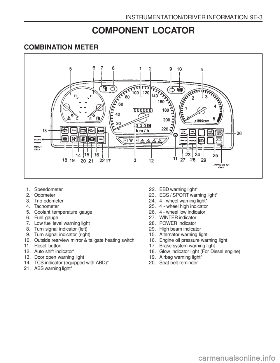
COMBINATION METER
COMPONENT LOCATOR
1. Speedometer
2. Odometer
3. Trip odometer
4. Tachometer
5. Coolant temperature gauge
6. Fuel gauge
7. Low fuel level warning light
8. Turn signal indicator (left)
9. Turn signal indicator (right)
10. Outside rearview mirror & tailgate heating switch
11. Reset button
12. Auto shift indicator*
13. Door open warning light
14. TCS indicator (equipped with ABD)*
21. ABS warning light* 22. EBD warning light*
23. ECS / SPORT warning light*
24. 4 - wheel warning light*
25. 4 - wheel high indicator
26. 4 - wheel low indicator
27. WINTER indicator
28. POWER indicator
29. High beam indicator
15. Alternator warning light
16. Engine oil pressure warning light
17. Brake system warning light
18. Glow indicator light (For Diesel engine)
19. Airbag warning light*
20. Seat belt reminder
Page 1267 of 1574

SECTION 9L
GLASS AND MIRRORS
Caution: Disconnect the negative battery cable before removing or installing any electrical unit or when a tool or equipment could easily come in contact with exposed electrical terminals. Disconnecting this cable will help prevent personal injury and damage to the vehicle. The ignition must also be in LOCK unless otherwisenoted.TABLE OF CONTENTS
Schematic and Routing Diagrams . . . . . . . . 9L-2 Outside Mirror . . . . . . . . . . . . . . . . . . . . . . . . . 9L-2
Auto Dimming Room Mirror . . . . . . . . . . . . . . . 9L-3
Maintenance and Repair . . . . . . . . . . . . . . . 9L-4 On-Vehicle Service . . . . . . . . . . . . . . . . . . . . . .
9L-4
Front & Side Glass . . . . . . . . . . . . . . . . . . . . . 9L-4
Tailgate Glass . . . . . . . . . . . . . . . . . . . . . . . . . 9L-9
Auto Dimming Room Mirror . . . . . . . . . . . . . . 9L-12
Page 1268 of 1574

9L-2 GLASS AND MIRRORS
OUTSIDE MIRROR
SCHEMATIC AND ROUTING DIAGRAMS
Page 1269 of 1574

GLASS AND MIRRORS 9L-3
AUTO DIMMING ROOM MIRROR