reset SSANGYONG MUSSO 2003 Service Manual
[x] Cancel search | Manufacturer: SSANGYONG, Model Year: 2003, Model line: MUSSO, Model: SSANGYONG MUSSO 2003Pages: 1574, PDF Size: 26.41 MB
Page 604 of 1574

1F1-72 M162 ENGINE CONTROLS
OXYGEN SENSOR
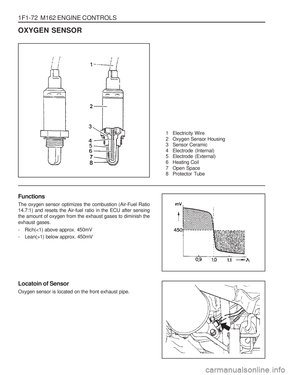
1 Electricity Wire
2 Oxygen Sensor Housing
3 Sensor Ceramic
4 Electrode (Internal)
5 Electrode (External)
6 Heating Coil
7 Open Space
8 Protector Tube
Functions The oxygen sensor optimizes the combustion (Air-Fuel Ratio 14.7:1) and resets the Air-fuel ratio in the ECU after sensingthe amount of oxygen from the exhaust gases to diminish the exhaust gases.
- Rich(<1) above approx. 450mV
- Lean(>1) below approx. 450mV
Locatoin of Sensor Oxygen sensor is located on the front exhaust pipe.
Page 704 of 1574

SUSPENSION DIAGNOSIS 2A-7
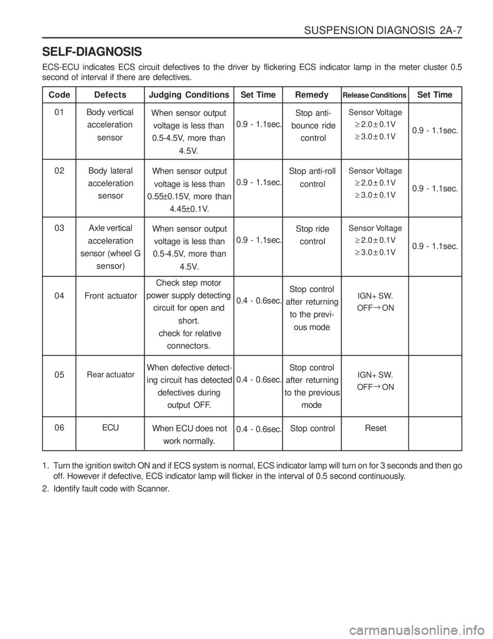
SELF-DIAGNOSIS ECS-ECU indicates ECS circuit defectives to the driver by flickering ECS indicator lamp in the meter cluster 0.5 second of interval if there are defectives.
Code
Body verticalacceleration
sensor
Defects
When sensor outputvoltage is less than
0.5-4.5V, more than
4.5V.
Judging Conditions01
0.9 - 1.1sec.Set TimeSensor Voltage
�2.0 ± 0.1V
� 3.0 ± 0.1V
Release Conditions
0.9 - 1.1sec.
Set Time
Body lateral
acceleration sensor When sensor output
voltage is less than
0.55±0.15V, more than
4.45±0.1V.
02
0.9 - 1.1sec.Sensor Voltage
�2.0 ± 0.1V
� 3.0 ± 0.1V 0.9 - 1.1sec.
Stop anti-
bounce ride
control
Remedy
Stop anti-roll control
Axle vertical
acceleration
sensor (wheel G sensor) When sensor output
voltage is less than
0.5-4.5V, more than
4.5V.
03
0.9 - 1.1sec.Sensor Voltage
�2.0 ± 0.1V
� 3.0 ± 0.1V 0.9 - 1.1sec.
Stop ride
control
Front actuator Check step motor
power supply detecting
circuit for open and
short.
check for relative connectors.
04
0.4 - 0.6sec.IGN+ SW.
OFF �
ON
Stop control
after returning to the previ-
ous mode
Rear actuator When defective detect- ing circuit has detected
defectives during
output OFF.
05
0.4 - 0.6sec.IGN+ SW.
OFF �
ON
Stop control
after returning
to the previous
mode
ECU When ECU does not
work normally.
06
0.4 - 0.6sec.Reset
Stop control
1. Turn the ignition switch ON and if ECS system is normal, ECS indicator lamp will turn on for 3 seconds and then go off. However if defective, ECS indicator lamp will flicker in the interval of 0.5 second continuously.
2. Identify fault code with Scanner.
Page 1104 of 1574

TRANSFER CASE (TOD) 5D2-15
DIAGNOSIS
While the TCCU is active it periodically monitors its inputs and outputs. If a fault is detected the “4WD CHECK ” lamp
is illuminated and a fault code is stored in the TCCU memory.
When requested, fault codes are downloaded to a diagnostic connector (K-line) serial communications using SCAN- 100. DIAGNOSTIC TESTS 1.TCCU Internal Function
When the Ignition is turned on the TCCU tests its ROM and RAM. If there is a fault, the TCCU immediately resets itself and re-tests the ROM and RAM. If the fault persists the TCCU continues to reset and re-test until the fault is corrected or the ignition is turned off. All TCCU functions are inhibited until the fault is corrected. The “4WD
CHECK ” lamp is not illuminated if there is a ROM or RAM fault.
If the ROM/RAM passes the EEPROM memory is tested. If there is a fault the “4WD CHECK ” lamp is illuminated
and the TCCU continues to operate using the default calibration data stored in ROM. Fault codes are not storedwhen there is an EEPROM fault.
An EEPROM fault can only be cleared by cycling ignition off-on.
2.Shift Motor Assembly Test If the TCCU detects a shift motor or position encoder fault continuously for one second the ‘4WD CHECK ” lamp is
turned on and the appropriate fault code is stored in memory.
a. A shift motor fault when the motor is off is defined as follows:
Motor H-L shorted to GroundMotor L-H shorted to GroundMotor open circuit
b. A shift motor fault when the motor is energized is defined as follows: Motor H-L shorted to GroundMotor L-H shorted to GroundMotor H-L shorted to Motor L-H Motor open circuit
c. A position encoder fault is defined as follows: Any position code which does not correspond to the valid 9 codes. A short to ground on any of the encoder lines.
d. If no shifts are in progress when a failure occurs the TCCU will not respond to any shift commands.
e. If a shift command has been received, but not acted upon when a failure occurs the TCCU will cancel the command and not respond to any subsequent shift commands.
f. If a shift command is in progress when an invalid position code is confirmed it will be halted and the TCCU will turn the motor toward the high position. Afterwards the TCCU will not respond to any shift commands.
Page 1252 of 1574

INSTRUMENTATION/DRIVER INFORMATION 9E-3
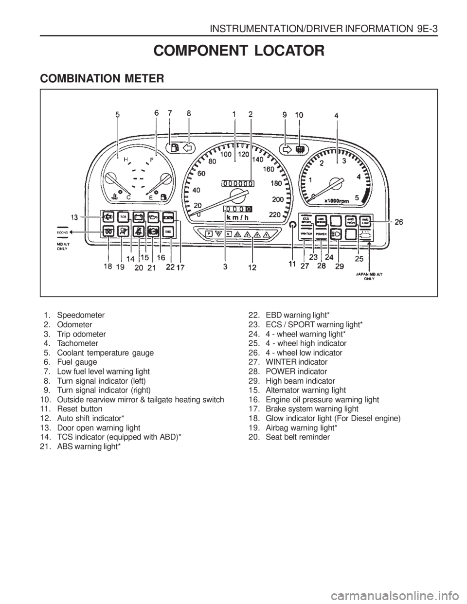
COMBINATION METER
COMPONENT LOCATOR
1. Speedometer
2. Odometer
3. Trip odometer
4. Tachometer
5. Coolant temperature gauge
6. Fuel gauge
7. Low fuel level warning light
8. Turn signal indicator (left)
9. Turn signal indicator (right)
10. Outside rearview mirror & tailgate heating switch
11. Reset button
12. Auto shift indicator*
13. Door open warning light
14. TCS indicator (equipped with ABD)*
21. ABS warning light* 22. EBD warning light*
23. ECS / SPORT warning light*
24. 4 - wheel warning light*
25. 4 - wheel high indicator
26. 4 - wheel low indicator
27. WINTER indicator
28. POWER indicator
29. High beam indicator
15. Alternator warning light
16. Engine oil pressure warning light
17. Brake system warning light
18. Glow indicator light (For Diesel engine)
19. Airbag warning light*
20. Seat belt reminder