sensor fuel SSANGYONG MUSSO 2003 Service Manual
[x] Cancel search | Manufacturer: SSANGYONG, Model Year: 2003, Model line: MUSSO, Model: SSANGYONG MUSSO 2003Pages: 1574, PDF Size: 26.41 MB
Page 357 of 1574
1B3-92 OM600 ENGINE MECHANICAL
28. Remove the connecting rod bearing cap.
29. Install the piston.
30. Rotate the crankshaft by hand and check whether it rotatessmoothly.
31. If the bearings are damaged,
- replace the oil presser relief valve. - clean the oil pump and oil filter housing carefully and
replace the hose if necessary. Notice After assembling the engine, check the camshaft timing, adjust the start of fuel injection and check the TDC sensorbracket setting.
32. Fill oil and run the engine and then check the oil pressure and oil level. Notice Install the original oil filter element and then change the engine oil and oil filter element after 1,000 - 1,500km.
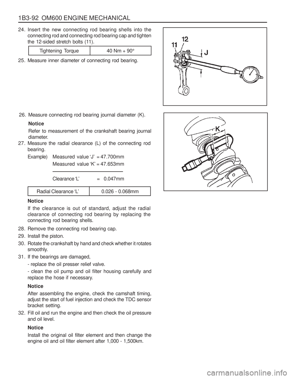
27. Measure the radial clearance (L) of the connecting rod
bearing. Example) Measured value ‘J’ = 47.700mm
Measured value ‘K’ = 47.653mm
Clearance ‘L’ = 0.047mm
Radial Clearance ‘L’0.026 - 0.068mm
Notice If the clearance is out of standard, adjust the radial clearance of connecting rod bearing by replacing theconnecting rod bearing shells.
26. Measure connecting rod bearing journal diameter (K).
Notice Refer to measurement of the crankshaft bearing journal
diameter.
24. Insert the new connecting rod bearing shells into theconnecting rod and connecting rod bearing cap and tighten
the 12-sided stretch bolts (11).
25. Measure inner diameter of connecting rod bearing.
Tightening Torque 40 Nm + 90 °
Page 533 of 1574

SECTION 1F1
M162 ENGINE CONTROLS
TABLE OF CONTENTS
CAUTION: Disconnect the negative battery cable before removing or installing any electrical unit or when a tool or equipment could easily come in contact with exposed electrical terminals. Disconnecting this cablewill help prevent personal injury and damage to the vehicle. The ignition must also be in LOCK unless otherwisenoted.
Specifications . . . . . . . . . . . . . . . . . . . . . . . 1F1-2
Fastener Tightening Specifications . . . . . . . . 1F1-2
Special Tools . . . . . . . . . . . . . . . . . . . . . . . 1F1-3 Special Tools Table . . . . . . . . . . . . . . . . . . . . 1F1-3
Schematic and Routing Diagrams . . . . . . . 1F1-4 E32 ECU (HFM) . . . . . . . . . . . . . . . . . . . . . . 1F1-4
E32 ECU (MSE) . . . . . . . . . . . . . . . . . . . . . . 1F1-5
Diagnosis . . . . . . . . . . . . . . . . . . . . . . . . . . 1F1-6
Self Diagnosis Socket Pin Numbers andDescriptions . . . . . . . . . . . . . . . . . . . . . . . . 1F1-6
Self Diagnosis Failure Code . . . . . . . . . . . . . 1F1-7
Test Box Connection . . . . . . . . . . . . . . . . . . 1F1-10
Fuel Injection System Test (MSE3.62) . . . . . 1F1-11
Ignition System Test . . . . . . . . . . . . . . . . . . 1F1-21
Idling Control and Electronic Pedal System Test . . . . . . . . . . . . . . . . . . . . . . . 1F1-26
Air Conditioner Control System Test . . . . . . 1F1-28
Fuel Pressure and Internal Leakage Test . . 1F1-29
Fuel Pump Test . . . . . . . . . . . . . . . . . . . . . . 1F1-31Injector Test . . . . . . . . . . . . . . . . . . . . . . . .
1F1-33
Maintenance and Repair . . . . . . . . . . . . . 1F1-35
On-Vehicle Service . . . . . . . . . . . . . . . . . . . . 1F1-35
ECU . . . . . . . . . . . . . . . . . . . . . . . . . . . . . . 1F1-35
Fuel Pressure Regulator . . . . . . . . . . . . . . 1F1-46
Fuel Distributor . . . . . . . . . . . . . . . . . . . . . . 1F1-50
Injector . . . . . . . . . . . . . . . . . . . . . . . . . . . . 1F1-54
Fuel Filter . . . . . . . . . . . . . . . . . . . . . . . . . . 1F1-57
Fuel Pump . . . . . . . . . . . . . . . . . . . . . . . . . 1F1-58
Purge Switchover Valve . . . . . . . . . . . . . . . 1F1-62
Vacuum System . . . . . . . . . . . . . . . . . . . . . 1F1-64
Crankshaft Position Sensor . . . . . . . . . . . . 1F1-65
Camshaft Position Sensor . . . . . . . . . . . . . 1F1-67
Hot Film Air Mass (HFM) Sensor . . . . . . . . . 1F1-69
Oxygen Sensor . . . . . . . . . . . . . . . . . . . . . . 1F1-72
Knock Sensor . . . . . . . . . . . . . . . . . . . . . . . 1F1-74
Coolant Temperature Sensor . . . . . . . . . . . 1F1-75
Accelerator Pedal Module . . . . . . . . . . . . . . 1F1-78
Page 534 of 1574

1F1-2 M162 ENGINE CONTROLSSPECIFICATIONS
FASTENER TIGHTENING SPECIFICATIONS
Application
Fuel Return and Supply Line Fuel Distributor Assembly Bolt
Pressure Test ConnectorFuel Inlet and Outlet LineFuel Filter Mounting Bracket Bolt Crankshaft Position Sensor Bolt Camkshaft Position Sensor BoltKnock Sensor Mounting Bolt
Coolant Temperature BoltN m
25 - 30
22.5 - 27.5 21.6 - 26.4 25 - 304 - 8
9 - 11
9 - 11
22.5 - 27.5 18 - 22
Page 539 of 1574
M162 ENGINE CONTROLS 1F1-7
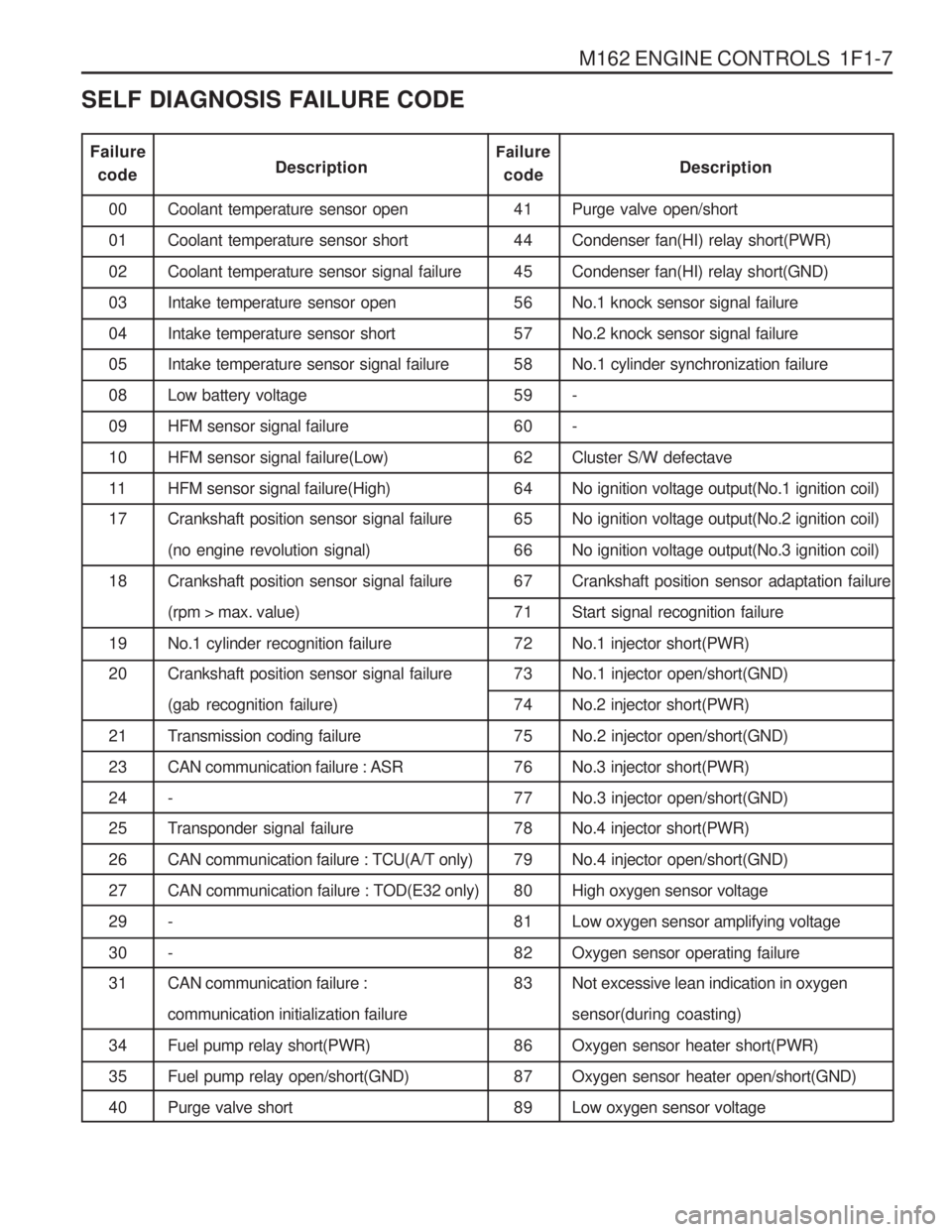
41 44455657 58 59606264 65 66677172 73 74757677 78 79808182 83 86 8789
0001 02 0304 05 08091011 17 1819 20 21 2324 25 26272930 31 34 3540
Failure
code Description
Coolant temperature sensor open Coolant temperature sensor shortCoolant temperature sensor signal failureIntake temperature sensor openIntake temperature sensor short Intake temperature sensor signal failure Low battery voltageHFM sensor signal failureHFM sensor signal failure(Low)HFM sensor signal failure(High) Crankshaft position sensor signal failure (no engine revolution signal)Crankshaft position sensor signal failure(rpm > max. value)No.1 cylinder recognition failure Crankshaft position sensor signal failure (gab recognition failure)
Transmission coding failureCAN communication failure : ASR-
Transponder signal failure CAN communication failure : TCU(A/T only)CAN communication failure : TOD(E32 only)-- CAN communication failure : communication initialization failureFuel pump relay short(PWR)Fuel pump relay open/short(GND)Purge valve short
Fa
ilure
code Description
Purge valve open/short Condenser fan(HI) relay short(PWR)Condenser fan(HI) relay short(GND)No.1 knock sensor signal failureNo.2 knock sensor signal failure No.1 cylinder synchronization failure --Cluster S/W defectaveNo ignition voltage output(No.1 ignition coil) No ignition voltage output(No.2 ignition coil) No ignition voltage output(No.3 ignition coil)Crankshaft position sensor adaptation failureStart signal recognition failureNo.1 injector short(PWR) No.1 injector open/short(GND) No.2 injector short(PWR)No.2 injector open/short(GND)No.3 injector short(PWR)No.3 injector open/short(GND) No.4 injector short(PWR) No.4 injector open/short(GND)High oxygen sensor voltageLow oxygen sensor amplifying voltageOxygen sensor operating failure Not excessive lean indication in oxygen sensor(during coasting)Oxygen sensor heater short(PWR)Oxygen sensor heater open/short(GND)Low oxygen sensor voltage
SELF DIAGNOSIS FAILURE CODE
Page 540 of 1574
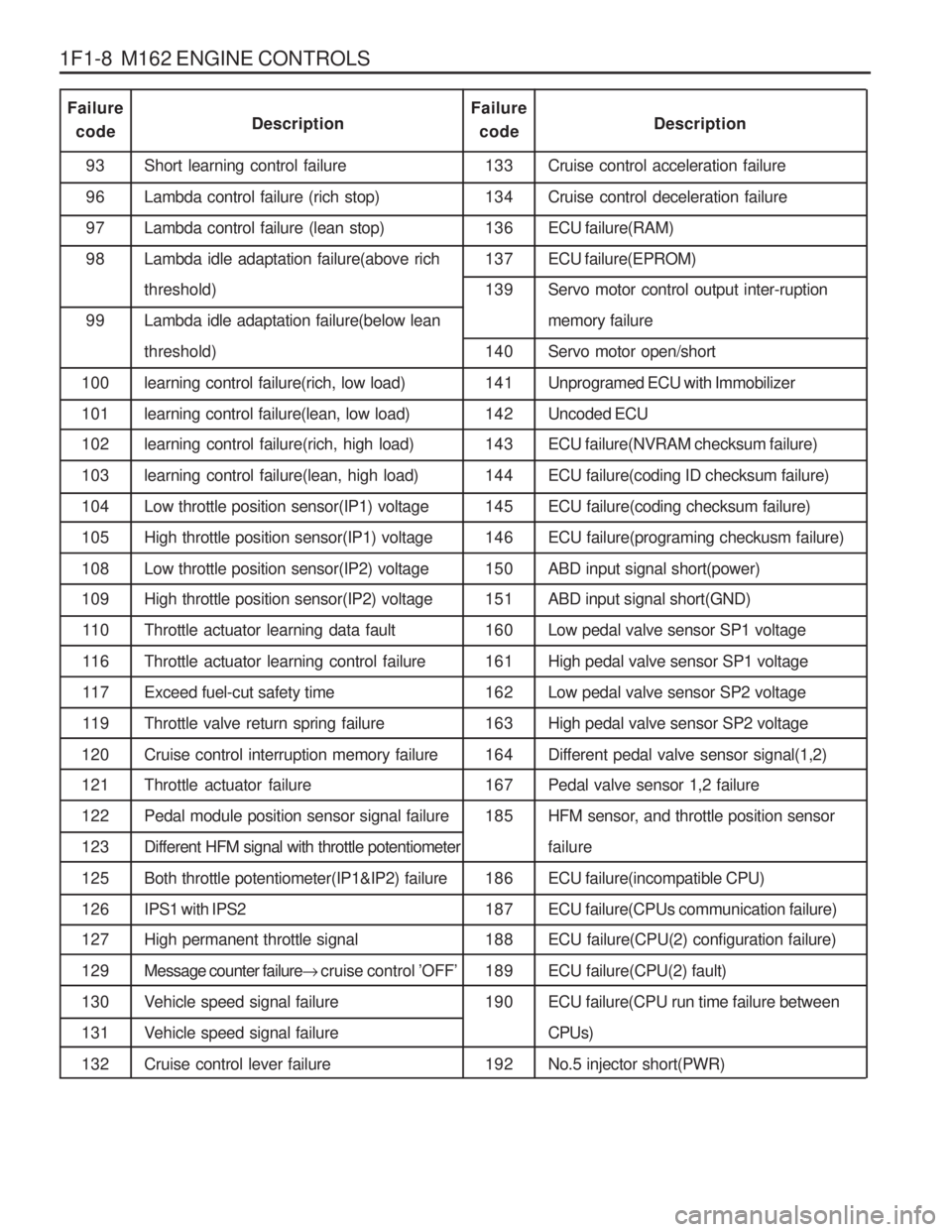
1F1-8 M162 ENGINE CONTROLSCruise control acceleration failure Cruise control deceleration failureECU failure(RAM)ECU failure(EPROM) Servo motor control output inter-ruption memory failureServo motor open/shortUnprogramed ECU with Immobilizer Uncoded ECU ECU failure(NVRAM checksum failure) ECU failure(coding ID checksum failure)ECU failure(coding checksum failure)ECU failure(programing checkusm failure)ABD input signal short(power) ABD input signal short(GND) Low pedal valve sensor SP1 voltageHigh pedal valve sensor SP1 voltageLow pedal valve sensor SP2 voltageHigh pedal valve sensor SP2 voltageDifferent pedal valve sensor signal(1,2) Pedal valve sensor 1,2 failure
HFM sensor, and throttle position sensorfailureECU failure(incompatible CPU)ECU failure(CPUs communication failure) ECU failure(CPU(2) configuration failure) ECU failure(CPU(2) fault)ECU failure(CPU run time failure betweenCPUs)No.5 injector short(PWR)
93969798 99
100 101 102 103 104 105108 109 11 0
11 6
11 7
11 9
120 121 122123125126 127 129130131132 Short learning control failureLambda control failure (rich stop)Lambda control failure (lean stop) Lambda idle adaptation failure(above rich threshold) Lambda idle adaptation failure(below lean threshold)learning control failure(rich, low load)learning control failure(lean, low load) learning control failure(rich, high load) learning control failure(lean, high load)Low throttle position sensor(IP1) voltageHigh throttle position sensor(IP1) voltageLow throttle position sensor(IP2) voltage High throttle position sensor(IP2) voltage Throttle actuator learning data faultThrottle actuator learning control failureExceed fuel-cut safety timeThrottle valve return spring failureCruise control interruption memory failure Throttle actuator failure Pedal module position sensor signal failureDifferent HFM signal with throttle potentiometerBoth throttle potentiometer(IP1&IP2) failureIPS1 with IPS2 High permanent throttle signal Message counter failure
� cruise control ’OFF ’
Vehicle speed signal failure
Vehicle speed signal failureCruise control lever failure 133134 136 137 139 140 141142 143 144145146150 151 160161162163164 167 185 186 187 188 189190 192
Failure
code DescriptionFailure
code Description
Page 545 of 1574
M162 ENGINE CONTROLS 1F1-13
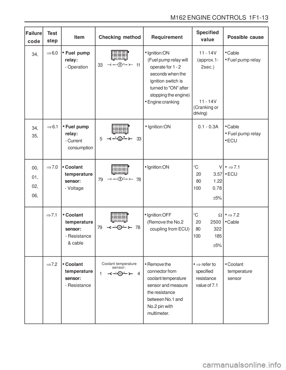
Failurecode ItemChecking method
Te s t
stepRequirementSpecified value Possible cause
� 6.1
Ignition:ON 0.1 - 0.3A
Cable
Fuel pump relay
ECU
Fuel pump
relay: - Current consumption
00, 01, 02, 06, �
7.0
Coolant
temperature sensor:- Voltage 79 78
Ignition:ON °CV
20 3.57
80 1.22
100 0.78
� 7.1
ECU
± 5%
�
6.0
Ignition:ON
(Fuel pump relay will operate for 1 - 2seconds when theignition switch isturned to "ON" afterstopping the engine)
Engine:cranking
33 11
Cable
Fuel pump relay
Fuel pump
relay:- Operation
34, 11 - 14V
(approx.1- 2sec.)
11 - 14V
(Cranking or driving)
53 3
� 7.1
Ignition:OFF
(Remove the No.2 coupling from ECU)
79 78
� 7.2
Cable
Coolant
temperature sensor:- Resistance & cable °
C �
20 2500 80 322
100 185
± 5%
� 7.2
Coolant
temperature sensor:- Resistance Coolant temperature
sensor:
14 Remove the
connector from coolant temperaturesensor and measurethe resistancebetween No.1 andNo.2 pin withmultimeter.
� refer to
specifiedresistancevalue of 7.1
Coolant
temperaturesensor
34, 35,
Page 590 of 1574

1F1-58 M162 ENGINE CONTROLS
FUEL PUMP
Requirements for Fuel Pump
ItemSpecified ValueItemSpecified Value
System Pressure3.8 bar
Minimum Delivery at 8V 30 Litre/Hr
Maximum Pressure 8.5 bar (12 V)
Minimum Amount of Fuel Supply 114 Liter/Hr (12 V, 3.8 bar, -
30 ~ +70 °C)
Minimum Pressure 5.0 bar (12 V) Maximum Allowable Current
7.5 A
Nominal Voltage12 VAmbient Temperature -30 ~ +70°C
1 Reservoir Tank
2 Fuel Sensor (float/arm)
3 Resistance
4 Wiring Connector
5 Fuel Supply Pipe
7 Float
10 Flange and Harness Assembly 11 Fuel Pump
12 Spring
13 Thermister Housing
14 Thermister
15 Resistor Card and Wiper
16 Float Arm
Operating Voltage 8 V
Maximum Amount of Fuel Supply 165 Liter/Hr (12V, 3.8 bar,
-30 ~ +70 °C)
Page 604 of 1574
1F1-72 M162 ENGINE CONTROLS
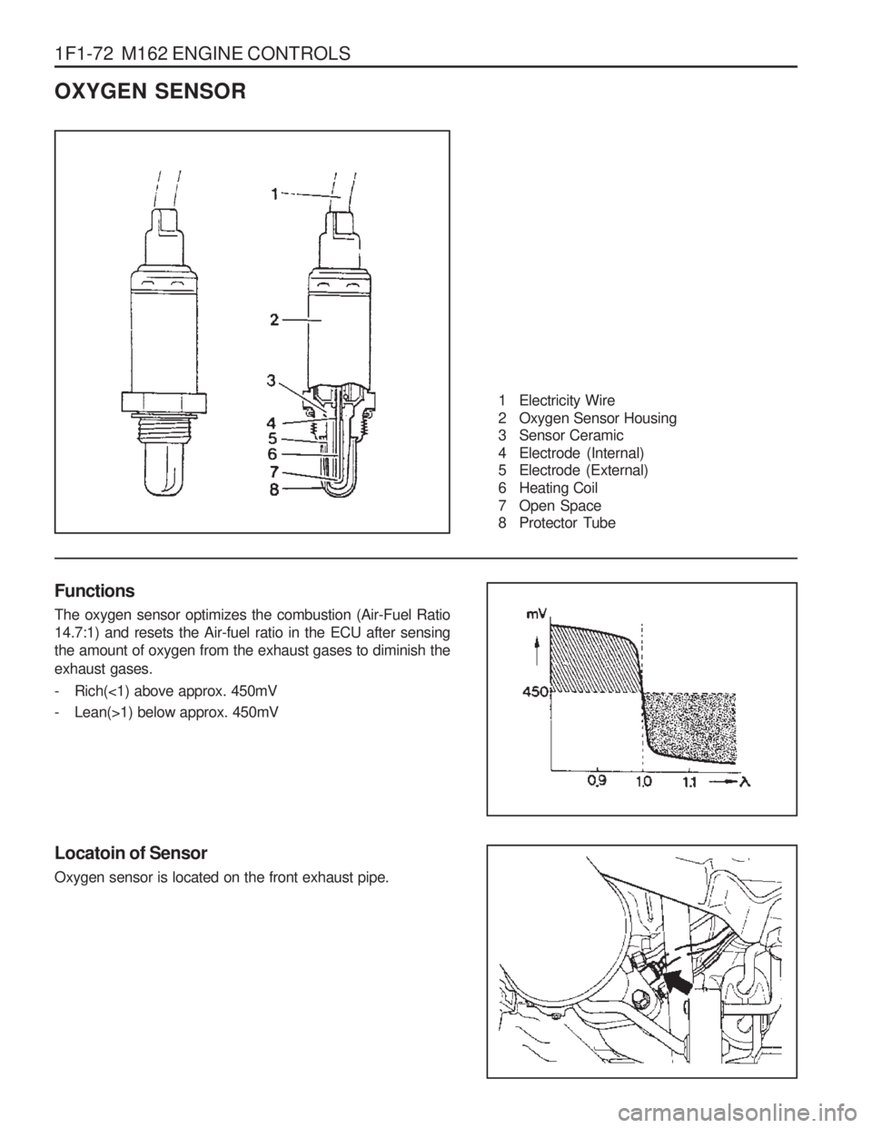
OXYGEN SENSOR
1 Electricity Wire
2 Oxygen Sensor Housing
3 Sensor Ceramic
4 Electrode (Internal)
5 Electrode (External)
6 Heating Coil
7 Open Space
8 Protector Tube
Functions The oxygen sensor optimizes the combustion (Air-Fuel Ratio 14.7:1) and resets the Air-fuel ratio in the ECU after sensingthe amount of oxygen from the exhaust gases to diminish the exhaust gases.
- Rich(<1) above approx. 450mV
- Lean(>1) below approx. 450mV
Locatoin of Sensor Oxygen sensor is located on the front exhaust pipe.
Page 612 of 1574
SECTION 1F3
OM600 ENGINE CONTROLS
Specifications . . . . . . . . . . . . . . . . . . . . . . . 1F3-1Fastener Tightening Specifications . . . . . . . . 1F3-1
Maintenance and Repair . . . . . . . . . . . . . . 1F3-2
On-Vehicle Service . . . . . . . . . . . . . . . . . . . . 1F3-2
Fuel System . . . . . . . . . . . . . . . . . . . . . . . . . 1F3-2
Fuel Injection Pump Coding . . . . . . . . . . . . . 1F3-3
Fuel Tank . . . . . . . . . . . . . . . . . . . . . . . . . . . 1F3-4
Vacuum Control System Test . . . . . . . . . . . . 1F3-5
Vacuum Pump(Sectional View) . . . . . . . . . . 1F3-10
Vacuum Pump Test . . . . . . . . . . . . . . . . . . . 1F3-11
Vacuum Pump . . . . . . . . . . . . . . . . . . . . . . 1F3-13
Vacuum Unit Replacement . . . . . . . . . . . . . 1F3-15Idle Speed Adjustment . . . . . . . . . . . . . . . .
1F3-16
Fuel Pump Test . . . . . . . . . . . . . . . . . . . . . . 1F3-18
Fuel Pump . . . . . . . . . . . . . . . . . . . . . . . . . 1F3-21
Injection Nozzle Test . . . . . . . . . . . . . . . . . . 1F3-22
Injection Nozzles . . . . . . . . . . . . . . . . . . . . . 1F3-25
Injection Nozzle Repair . . . . . . . . . . . . . . . . 1F3-27
Removal and Installation of Injection Timing Device . . . . . . . . . . . . . . 1F3-30
Injection Timing Device . . . . . . . . . . . . . . . . 1F3-35
Start of Delivery Test (Position Sensor, RIV Method) . . . . . . . . . 1F3-37
Fuel Injection Pump . . . . . . . . . . . . . . . . . . 1F3-46
TABLE OF CONTENTS
Caution: Disconnect the negative battery cable before removing or installing any electrical unit or when a tool or equipment could easily come in contact with exposed electrical terminals. Disconnecting this cable will help prevent personal injury and damage to the vehicle. The ignition must also be in LOCK unless otherwisenoted.
SPECIFICATIONS
FASTENER TIGHTENING SPECIFICATIONS
Application
Fuel Tank Mounting Nut Fuel Pump Pressure Line Fuel Injection NozzleFuel Injection Pipe
Nozzle Tensioning NutScrew Plug Left-Hand Thread Bolt
N· m
28 - 47 13
35 - 40 18 8030 46
Page 647 of 1574

OM600 ENGINE CONTROLS 1F3-37
START OF DELIVERY TEST (POSITION SENSOR, RIV METHOD)1 Position Sensor
2 Battery
3 Fuel Injection Pump 4 Seal
....................................................... Replace
5 Screw Plug ................................................. 30Nm
Service Data
Start of Delivery (RIV) ATDC 14° - 16 °