ESP SSANGYONG NEW ACTYON SPORTS 2012 Owner's Manual
[x] Cancel search | Manufacturer: SSANGYONG, Model Year: 2012, Model line: NEW ACTYON SPORTS, Model: SSANGYONG NEW ACTYON SPORTS 2012Pages: 828, PDF Size: 91.28 MB
Page 320 of 828
15-170000-00
C. Idle Speed Controller
The idle speed controller consists of 2 principal modules:
The first module determines the required idle speed according to:
* The operating conditions of the engine (coolant temperature, gear engaged)
* Any activation of the electrical consumers (power steering, air conditioning, others)
* The battery voltage
* The presence of any faults liable to interface with the rail pressure control or the injection
control. In this case, increase the idle speed to prevent the engine from stalling.
The second module is responsible for providing closed loop control of the engine's idle speed
by adapting the minimum fuel according to the difference between the required idle speed and
the engine speed. -
-
D. Flow Limitation
The flow limitation strategy is based on the following strategies:
The flow limitation depending on the filling of the engine with air is determined according to
the engine speed and the air flow. This limitation allows smoke emissions to be reduced
during stabilized running.
The flow limitation depending on the atmospheric pressure is determined according to the
engine speed and the atmospheric pressure. It allows smoke emissions to be reduced
when driving at altitude.
The full load flow curve is determined according to the gear engaged and the engine
speed. It allows the maximum torque delivered by the engine to be limited.
A performance limitation is introduced if faults liable to upset the rail pressure control or the
injection control are detected by the system. In this case, and depending on the gravity of
the fault, the system activates: -
-
-
-
Reduced fuel logic 1: Guarantees 75 % of the performance without limiting the engine speed.
Reduced fuel logic 2: Guarantees 50 % of the performance with the engine speed limited to
3,000 rpm.
Reduce fuel logic 3: Limits the engine speed to 2,000 rpm.
The system chooses the lowest of all values.
A correction depending on the coolant temperature is added to the flow limitation. This correction
makes it possible to reduce the mechanical stresses while the engine is warming up.
The correction is determined according to the coolant temperature, the engine speed and the
time which has passed since starting.
E. Superchager Flow Demand
The supercharge flow is calculated according to the engine speed and the coolant temperature. A
correction depending on the air temperature and the atmospheric pressure is made in order to
increase the supercharge flow during cold starts. It is possible to alter the supercharge flow value
by adding a flow offset with the aid of the diagnostic tool
Page 324 of 828
15-210000-00
(7) Knocking Control
A. Resetting the pilot injection
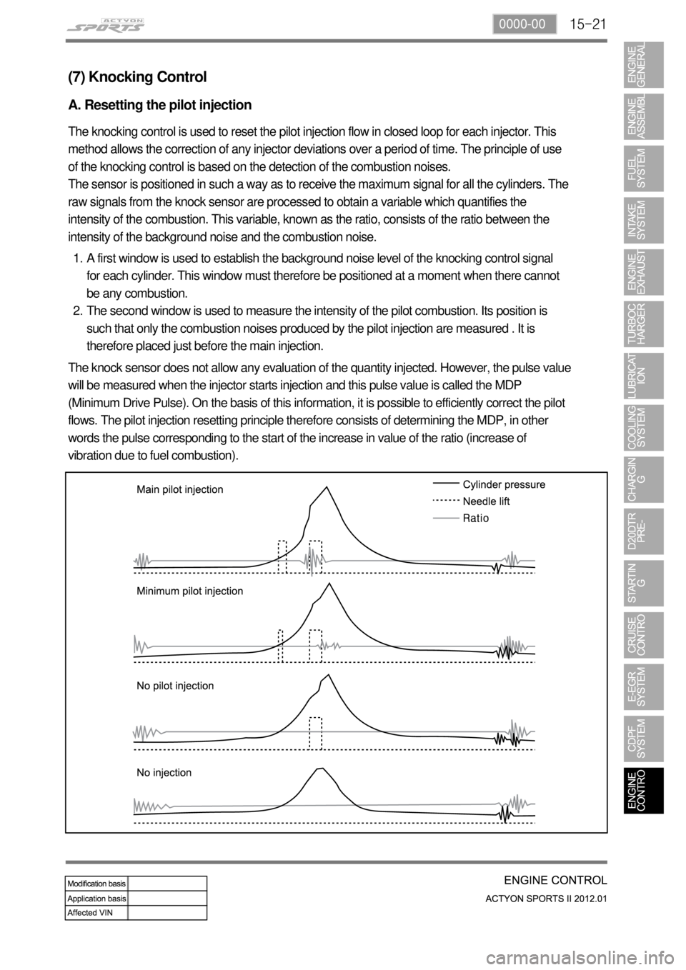
The knocking control is used to reset the pilot injection flow in closed loop for each injector. This
method allows the correction of any injector deviations over a period of time. The principle of use
of the knocking control is based on the detection of the combustion noises.
The sensor is positioned in such a way as to receive the maximum signal for all the cylinders. The
raw signals from the knock sensor are processed to obtain a variable which quantifies the
intensity of the combustion. This variable, known as the ratio, consists of the ratio between the
intensity of the background noise and the combustion noise.
A first window is used to establish the background noise level of the knocking control signal
for each cylinder. This window must therefore be positioned at a moment when there cannot
be any combustion.
The second window is used to measure the intensity of the pilot combustion. Its position is
such that only the combustion noises produced by the pilot injection are measured . It is
therefore placed just before the main injection. 1.
2.
The knock sensor does not allow any evaluation of the quantity injected. However, the pulse value
will be measured when the injector starts injection and this pulse value is called the MDP
(Minimum Drive Pulse). On the basis of this information, it is possible to efficiently correct the pilot
flows. The pilot injection resetting principle therefore consists of determining the MDP, in other
words the pulse corresponding to the start of the increase in value of the ratio (increase of
vibration due to fuel combustion).
Page 325 of 828
15-22
This is done periodically under certain operating conditions. When the resetting is finished, the
new minimum pulse value replaces the value obtained during the previous resetting. The first MDP
value is provided by the C3I. Each resetting then allows the closed loop of the MDP to be updated
according to the deviation of the injector.
B. Detection of leaks in the cylinders
The accelerometer is also used to detect any injector which may have stuck open. The detection
principle is based on monitoring the ratio. If there is a leak in the cylinder, the accumulated fuel
self-ignites as soon as the temperature and pressure conditions are favorable (high engine
speed, high load and small leak).
This combustion is set off at about 20 degrees before TDC and before main injection.
The ratio therefore increases considerably in the detection window. It is this increase which allows
the leaks to be detected. The threshold beyond which a fault is signaled is a percentage of the
maximum possible value of the ratio.
Because of the severity of the recovery process (engine shut-down), the etection must be
extremely robust.
An increase in the ratio can be the consequence of various causes:
Pilot injection too much
Main combustion offset
Fuel leak in the cylinder -
-
-
If the ratio becomes too high, the strategy initially restricts the pilot injection flow and retards the
main injection. If the ratio remains high despite these interventions, this shows that a real leak is
present, a fault is signaled and the engine is shut down.
C. Detection of an accelerometer fault
This strategy permits the detection of a fault in the sensor or in the wiring loom connecting the
sensor to the ECU.
It is based on detection of the combustion. When the engine is idling, the detection window is set
too low for the combustion caused by the main injection. If the ratio increases, this shows that the
knock sensor is working properly, but otherwise a fault is signaled to indicate a sensor failure.
The recovery modes associated with this fault consist of inhibition of the pilot injection and
discharge through the injectors.
Page 330 of 828
15-270000-00
(9) EGR control
A. Overview
The EGR (Electric-Exhaust Gas Recirculation) valve reduces the NOx emission level by
recirculating some of the exhaust gas to the intake system.
To meet Euro-V regulation, the capacity and response rate of E-EGR valve in D20DTR engine
have been greatly improved. The EGR cooler with high capacity reduces the Nox, and the bypass
valve reduces the CO and HC due to EGR gas before warming up.
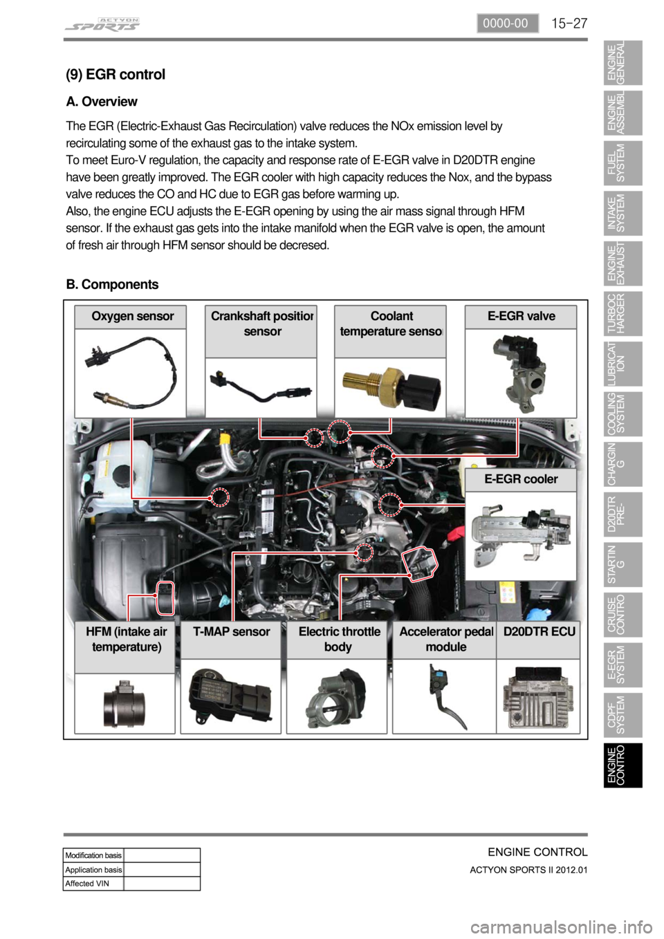
Also, the engine ECU adjusts the E-EGR opening by using the air mass signal through HFM
sensor. If the exhaust gas gets into the intake manifold when the EGR valve is open, the amount
of fresh air through HFM sensor should be decresed.
B. Components
E-EGR cooler
Accelerator pedal
moduleD20DTR ECU
Coolant
temperature senso
r
Oxygen sensor
HFM (intake air
temperature)Electric throttle
body
Crankshaft position
sensor
E-EGR valve
T-MAP sensor
Page 398 of 828
12-38510-23
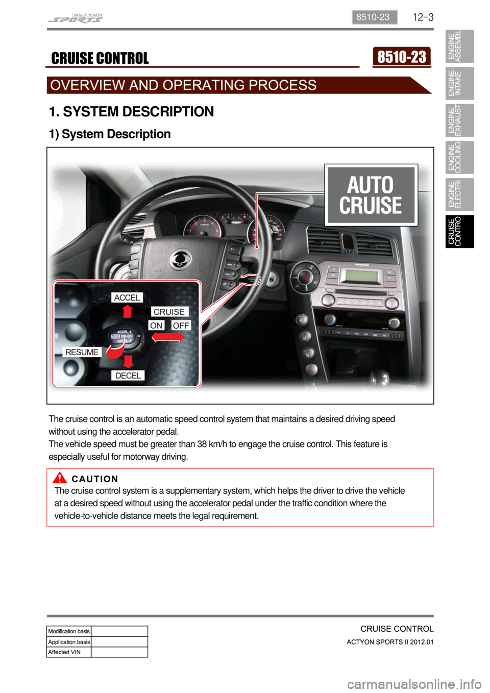
1. SYSTEM DESCRIPTION
1) System Description
The cruise control is an automatic speed control system that maintains a desired driving speed
without using the accelerator pedal.
The vehicle speed must be greater than 38 km/h to engage the cruise control. This feature is
especially useful for motorway driving.
The cruise control system is a supplementary system, which helps the driver to drive the vehicle
at a desired speed without using the accelerator pedal under the traffic condition where the
vehicle-to-vehicle distance meets the legal requirement.
Page 400 of 828
12-58510-23
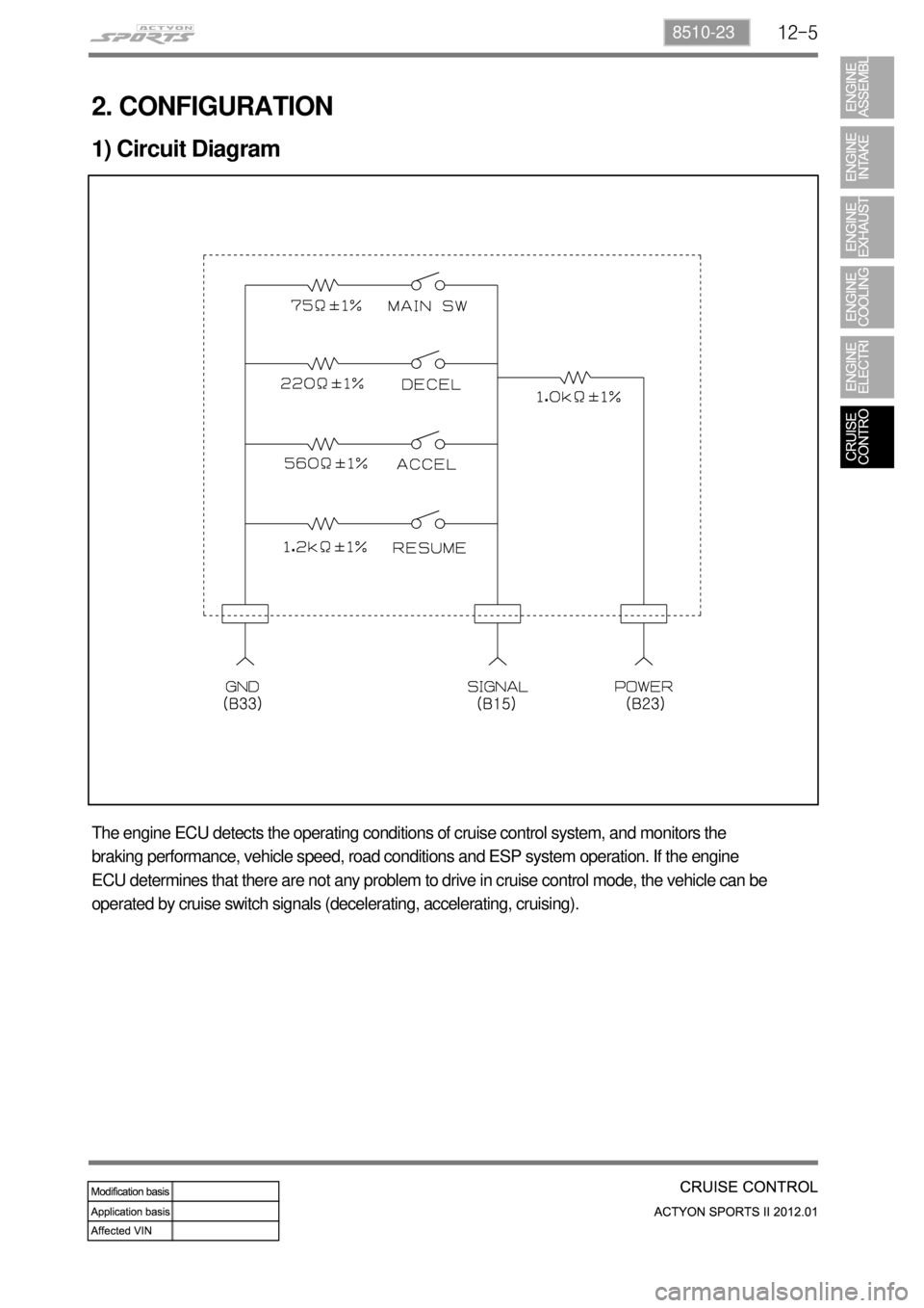
2. CONFIGURATION
1) Circuit Diagram
The engine ECU detects the operating conditions of cruise control system, and monitors the
braking performance, vehicle speed, road conditions and ESP system operation. If the engine
ECU determines that there are not any problem to drive in cruise control mode, the vehicle can be
operated by cruise switch signals (decelerating, accelerating, cruising).
Page 406 of 828
12-118510-23
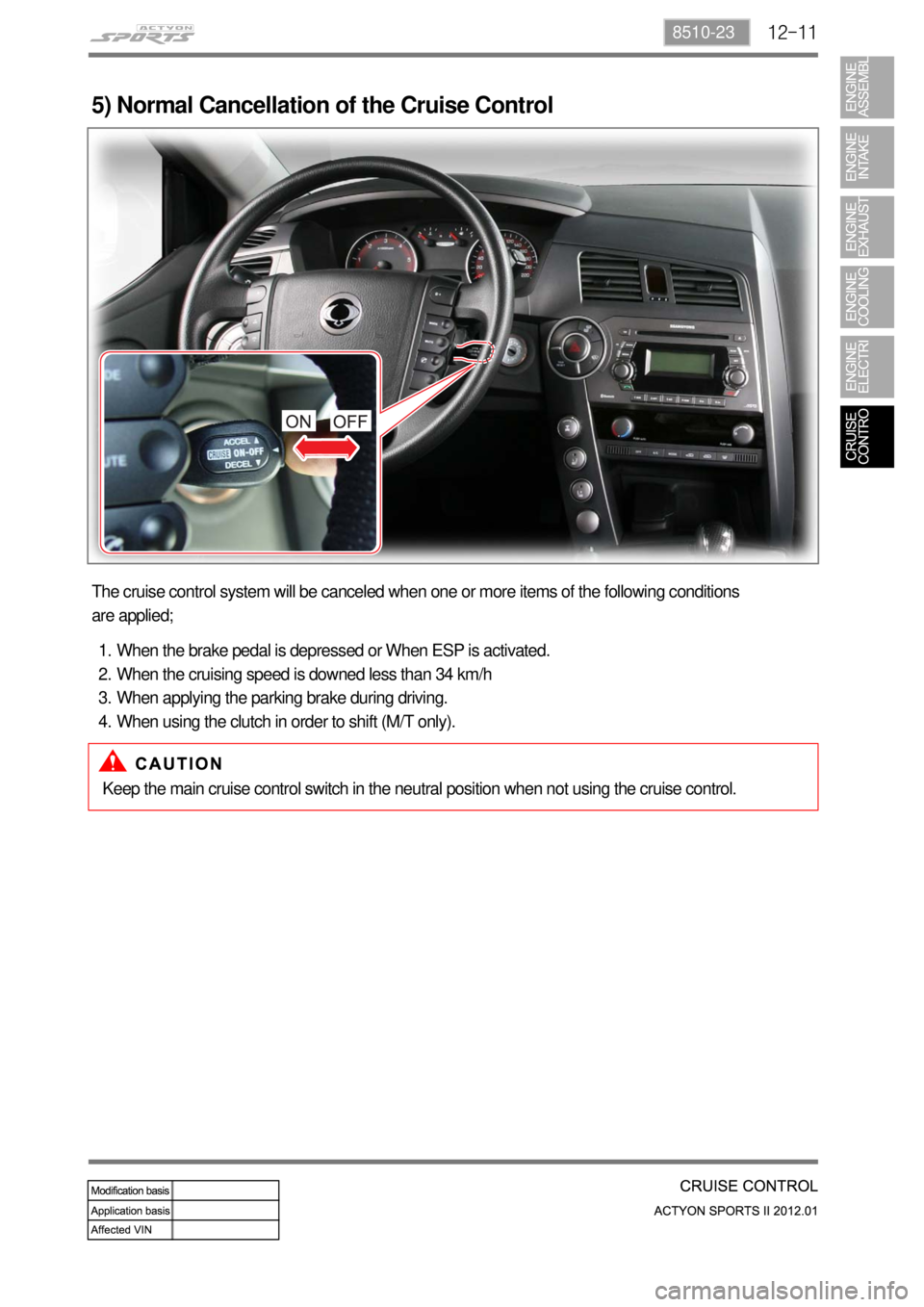
5) Normal Cancellation of the Cruise Control
The cruise control system will be canceled when one or more items of the following conditions
are applied;
When the brake pedal is depressed or When ESP is activated.
When the cruising speed is downed less than 34 km/h
When applying the parking brake during driving.
When using the clutch in order to shift (M/T only). 1.
2.
3.
4.
Keep the main cruise control switch in the neutral position when not using the cruise control.
Page 412 of 828
01-78410-02
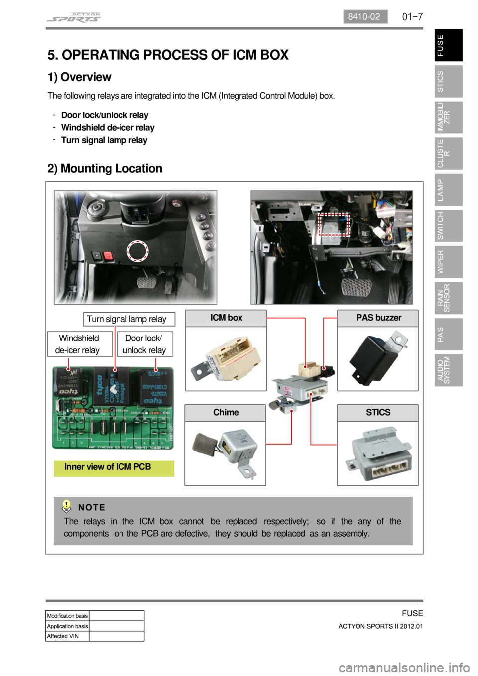
5. OPERATING PROCESS OF ICM BOX
The following relays are integrated into the ICM (Integrated Control Module) box.
Door lock/unlock relay
Windshield de-icer relay
Turn signal lamp relay -
-
-
1) Overview
2) Mounting Location
Door lock/
unlock relay
Turn signal lamp relay
Windshield
de-icer relay
Inner view of ICM PCB
PAS buzzer
Chime
ICM box
STICS
The relays in the ICM box cannot be replaced respectively; so if the any of the
components on the PCB are defective, they should be replaced as an assembly.
Page 413 of 828
01-8
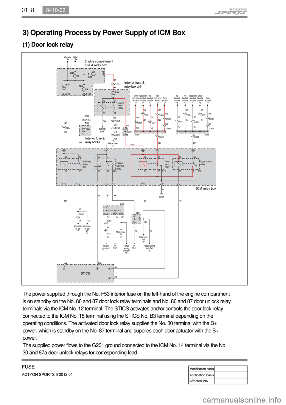
3) Operating Process by Power Supply of ICM Box
(1) Door lock relay
The power supplied through the No. F53 interior fuse on the left-hand of the engine compartment
is on standby on the No. 86 and 87 door lock relay terminals and No. 86 and 87 door unlock relay
terminals via the ICM No. 12 terminal. The STICS activates and/or controls the door lock relay
connected to the ICM No. 15 terminal using the STICS No. B3 terminal depending on the
operating conditions. The activated door lock relay supplies the No. 30 terminal with the B+
power, which is standby on the No. 87 terminal and supplies each door actuator with the B+
power.
The supplied power flows to the G201 ground connected to the ICM No. 14 terminal via the No.
30 and 87a door unlock relays for corresponding load.
Page 414 of 828
01-98410-02
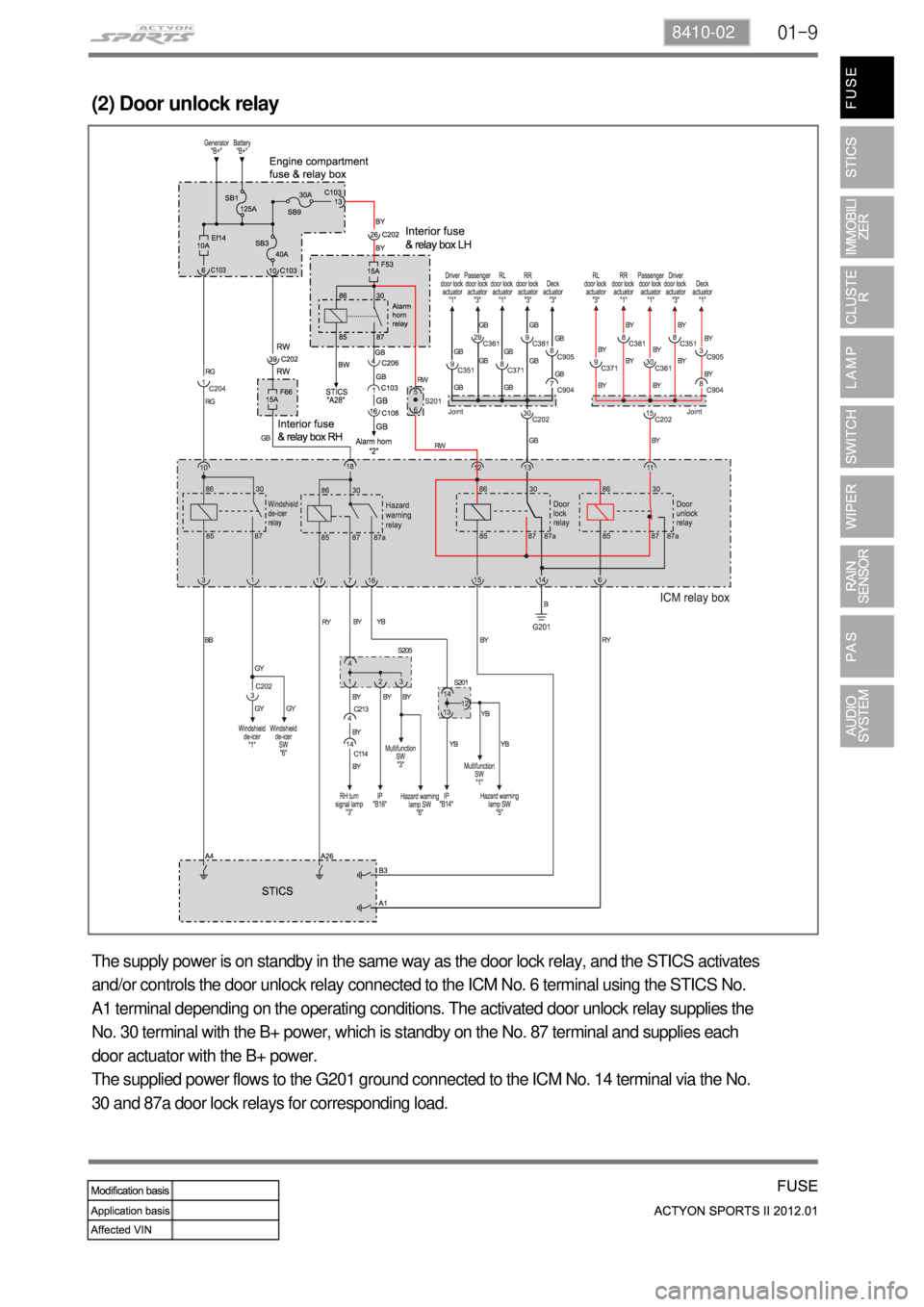
(2) Door unlock relay
The supply power is on standby in the same way as the door lock relay, and the STICS activates
and/or controls the door unlock relay connected to the ICM No. 6 terminal using the STICS No.
A1 terminal depending on the operating conditions. The activated door unlock relay supplies the
No. 30 terminal with the B+ power, which is standby on the No. 87 terminal and supplies each
door actuator with the B+ power.
The supplied power flows to the G201 ground connected to the ICM No. 14 terminal via the No.
30 and 87a door lock relays for corresponding load.