lock SSANGYONG NEW ACTYON SPORTS 2012 Service Manual
[x] Cancel search | Manufacturer: SSANGYONG, Model Year: 2012, Model line: NEW ACTYON SPORTS, Model: SSANGYONG NEW ACTYON SPORTS 2012Pages: 828, PDF Size: 91.28 MB
Page 3 of 828

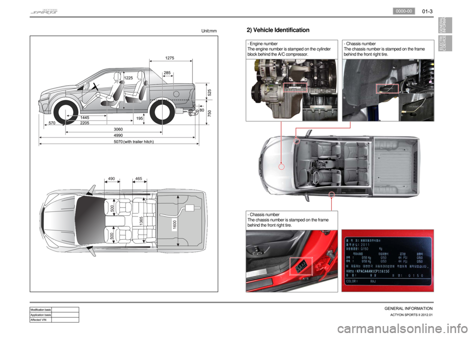
- Chassis number
The chassis number is stamped on the frame
behind the front right tire.
- Engine number
The engine number is stamped on the cylinder
block behind the A/C compressor.2) Vehicle Identification- Chassis number
The chassis number is stamped on the frame
behind the front right tire.
Unit:mm
Page 12 of 828

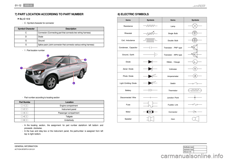
7) PART LOCATION ACCORDING TO PART NUMBER
Ex.) C 1 0 2 ▶
C : Symbol character for connector -Symbol Character Description
C Connector (Connecting part that connects two wiring harness)
D Diode
G Ground
S Splice pack (Joint connector that connects various wiring harness)
1 : Part location number -
Part number according to locating section -
Part Numbe Location
□ 1□□Engine compartment
□ 2□□Instrument panel
□ 3□□Passenger compartment
□ 4□□Tailgate
□ 9□□Underbody
In the locating section, the assignment for part number startsfrom left bottom and
proceeds clockwise.
In the fuse and relay box or the instrument panel, the partnumber is assigned from left
top to light bottom. -
-
8) ELECTRIC SYMBOLS
Page 37 of 828

1) DEICER RELAY, DR LOCK/UNLOCK RELAY 2) HAZARD RELAY
Page 38 of 828

3
4
5
8
11
1461-00/2820-00/1491-00/8210-00/3110-00/3410-00/4892-00/8810-00/8010-00/7410-100/8510-00/8710-00/8510-00/8610-00/
8730-00/7340-00/7632-00/8310-00/8610-00/8510-00/8320-00/8410-00/8210-00/8310-00/4810-00/7770-00/8910-00/8790-00/6810-00
ENGINE1461-00 STARTING / CHARGING.................
1413-00 GLOW CONTROL UNIT...................
1491-00 ECU (ENGINE CONTROL
UNIT - D20DTR EU-V).....................
1490-00 ECU (ENGINE CONTROL
UNIT - GSL G23)............................
8210-00 DIAGNOSIS CIRCUIT.....................CHASSIS3110-00 TCU (6-A/T)...................................
3410-00 TCCU............................................
4892-00 ABS/ESP........................................8730-00 IMMOBILIZER CIRCUIT................
7340-00 SUNROOF CIRCUIT.......................
7632-00 CIGAR LIGHTER / POWER
OUTLET CIRCUIT........................
8310-00 HEAD LAMP CIRCUIT..................
8610-00 DRL (DAY TIME RUNNING
LIGHT) UNIT CIRCUIT.................
8510-00 HLLD (HEAD LAMP LEVEL G
DEVICE) CIRCUIT.........................
8320-00 TAIL LAMP CIRCUIT....................
8410-00 TURN SIGNAL / HAZARD
LAMP CIRCUIT.............................
8210-00 TRAILER LAMP CIRCUIT.............
8310-00 FOG LAMP CIRCUIT.....................
4810-00 STOP / BACK-UP
LAMP CIRCUIT.............................
7770-00 INTERIOR LAMP CIRCUIT............
7770-00 AUTO DIMMING ROOM
MIRROR CIRCUT.........................
8910-00 AUDIO / CLOCK CIRCUIT..............
8790-00 PARKING AID CIRCUIT..................
6810-00 PTC HEATER (POSITIVE
TEMPERATURE COEFFICIENT).....
6810-00 FATC (FULL AUTO TEMP.
CONTROL) CIRCUIT....................
6810-00 AIR-CON (MANUAL) CIRCUIT......... 12
14
1533
34
35
36
37
38
39
40
41
42
43
44
45
46
47
48
49
52
'
ELECTRIC8810-00 AIR-BAG.......................................
8010-00 CLUSTER......................................
7410-00 POWER SEAT - DRIVER................
7410-00 POWER SEAT - PASSENGER.......
8510-00 ELECTRIC OUTSIDE MIRROR........
8510-00 SEAT WARMER.............................
8710-00 STICS.............................................
8510-00 POWER WINDOW CIRCUIT...........
8610-00 HORN............................................17
18
20
21
22
23
24
31
32
Page 62 of 828

2) CENTRAL DOOR LOCK CIRCUIT
(2) CONNECTOR IDENTIFICATION SYMBOL & PIN NUMBER POSITION (1) CONNECTOR INFORMATION
Page 97 of 828

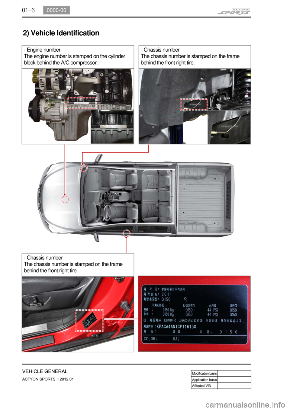
01-6
- Chassis number
The chassis number is stamped on the frame
behind the front right tire.- Engine number
The engine number is stamped on the cylinder
block behind the A/C compressor.
2) Vehicle Identification
- Chassis number
The chassis number is stamped on the frame
behind the front right tire.
Page 113 of 828

02-4
2330-01 Intercooler
Changed the bracket and core size
3030-01 Clutch pedal
Add clutch ECU switch
2130-07 Coolant reservoir
Changed the appearance and capacity
(2.8 L)
8410-02 Fuse box in engine
compartment
Changed the layout of relays
2. INTERIOR
Old
New
Old
New
OldNew
OldNew
Interlock
switch
7410-12 Seat logo
Old
New
Page 117 of 828

02-8
1533-08 Oil pan1533-48 Ladder frame
Deleted MBU, introduced ladder frame
1914-01 Turbocharger
Changed the cooling ty
pe (water cooling → air
cooling)
1729-01 Exhaust manifold
Changed the location of mounting flange and
exhaust gas temperature sensor mounting hole
1127-01 Cylinder block
D20DTF (Korando C)
4. MAJOR CHANGES IN ENGINE (LH)
OldNew
OldNew
OldNew
Exhaust gas
temperature
OldNew
OldNew
Plug screwPipe screw
Ladder frame
Page 140 of 828

02-30000-00
1. SPECIFICATION
Unit Description Specification Remark
Cylinder head Height 142.9 to 143.1 mm -
Flatness below 0.1 mm -
Valve protrusion Intake valve 0.1 to 0.7 mm -
Exhaust valve 0.1 to 0.7 mm -
Flatness on manifold
sideIntake manifold 0.08 mm -
Exhaust manifold 0.08 mm -
Connecting rod End play 0.5 to 1.5 mm -
Camshaft Axial end play Intake 0.1 to 0.35 mm -
Exhaust 0.1 to 0.35 mm -
Camshaft
position sensorDistance between Camshaft position
sensor and sprocket0.20 to 1.80 mm -
Valve Clearance between
valve and pistonIntake Approx. 0.7 mm -
Exhaust Approx. 0.8 mm -
Valve recess Intake 0.1 to 0.7 mm -
Exhaust -
Cylinder block Piston protrusion 0.541 to 0.649 mm -
Piston ring TOP ring end gap 0.20 to 0.35 mm -
2nd ring end gap 0.35 to 0.50 mm -
3rd ring end gap 0.2 to 0.40 mm -
Offset 0.3 mm -
Head gasket Piston protrusion 0.475~0.540 1.2t -
0.541 to 0.649 1.3t -
0.650 to 0.745 1.4t -
Page 142 of 828

02-50000-00
Component SizeBolt
QuantitySpecified torque
(Nm)Remark
(Total torque)
Hot water inlet pipeM6×16 2 10±1Nm -
AlternatorM10×90 1 25±2.5Nm -
M10×116 1 46±4.6Nm -
A/C bracketM8×25 4 7.8~11.8Nm -
A/C sub bracketM6×25 4 10±1Nm -
Intake manifoldM8×35 2 25±2.5Nm -
M8×110 6 25±2.5Nm -
Oil filter moduleM8×40 6 25±2.5Nm -
M8×20 1 25±2.5Nm -
M8×140 2 25±2.5Nm -
Knock sensorM8×28 2 20±5Nm -
Cam position sensorM8×14 1 10~14Nm -
Booster pressure
sensorM6×20 2 10±1Nm -
Exhaust manifold M8 10 40±4Nm -
Turbocharger M8 3 25±2.5Nm -
Support bolt 1 25±2.5Nm -
Support nut M8 1 25±2.5Nm -
T/C oil supply pipe M6(block side) 1 10±1.0Nm -
M6(turbo side) 1 17±2.0Nm -
T/C oil return pipeM6×16(turbo side)2 10±1Nm -
M6×16(block side)2 10±1Nm -
EGR valveM8×22 2 25±2.5Nm -
EGR pipe bolt
(Intake side)M8×16 2
25±2.5Nm -
EGR pipe bolt
(EGR cooler side)M8×16 2 25±2.5Nm -
EGR combination boltM6×16 4 10±1Nm -
M8×16 16 25±2.5Nm -
Idle pulley/Tensioner
pulley1 45±4.5Nm -