sensor SSANGYONG NEW ACTYON SPORTS 2013 User Guide
[x] Cancel search | Manufacturer: SSANGYONG, Model Year: 2013, Model line: NEW ACTYON SPORTS, Model: SSANGYONG NEW ACTYON SPORTS 2013Pages: 751, PDF Size: 72.63 MB
Page 38 of 751
02-70000-00
3. CHECK AND INSPECTION
1) Cylinder
(1) Compression pressure test
Specified value ▶
Compression ratio16.5 : 1
Test conditionat normal operating temperature (80˚C)
Compression pressureStandard32 bar
Minimum18 bar
Differential limit between cylindersMaximum 3 bar
The compression pressure test is to check the conditions of internal components (piston, piston ring,
intake and exhaust vale, cylinder head gasket). This test provides current engine operating status.
Before cranking the engine, make sure that the test wiring, tools and persons are keeping away
from moving components of engine (e.g., belt and cooling fan).
Park the vehicle on the level ground and apply the parking brake.
Do not allow anybody to be in front of the vehicle. -
-
-
Measurement ▶
<007e0088009900940047009b008f008c0047008c0095008e00900095008c0047009c00970047009b00960047009500960099009400880093004700960097008c00990088009b00900095008e0047009b008c00940097008c00990088009b009c0099008c00
47004f005f005700b6006a00500055>
Disconnect the fuel rail pressure sensor connector to cut off the fuel injection.
Remove the air cleaner duct and glow plugs. -
-
-
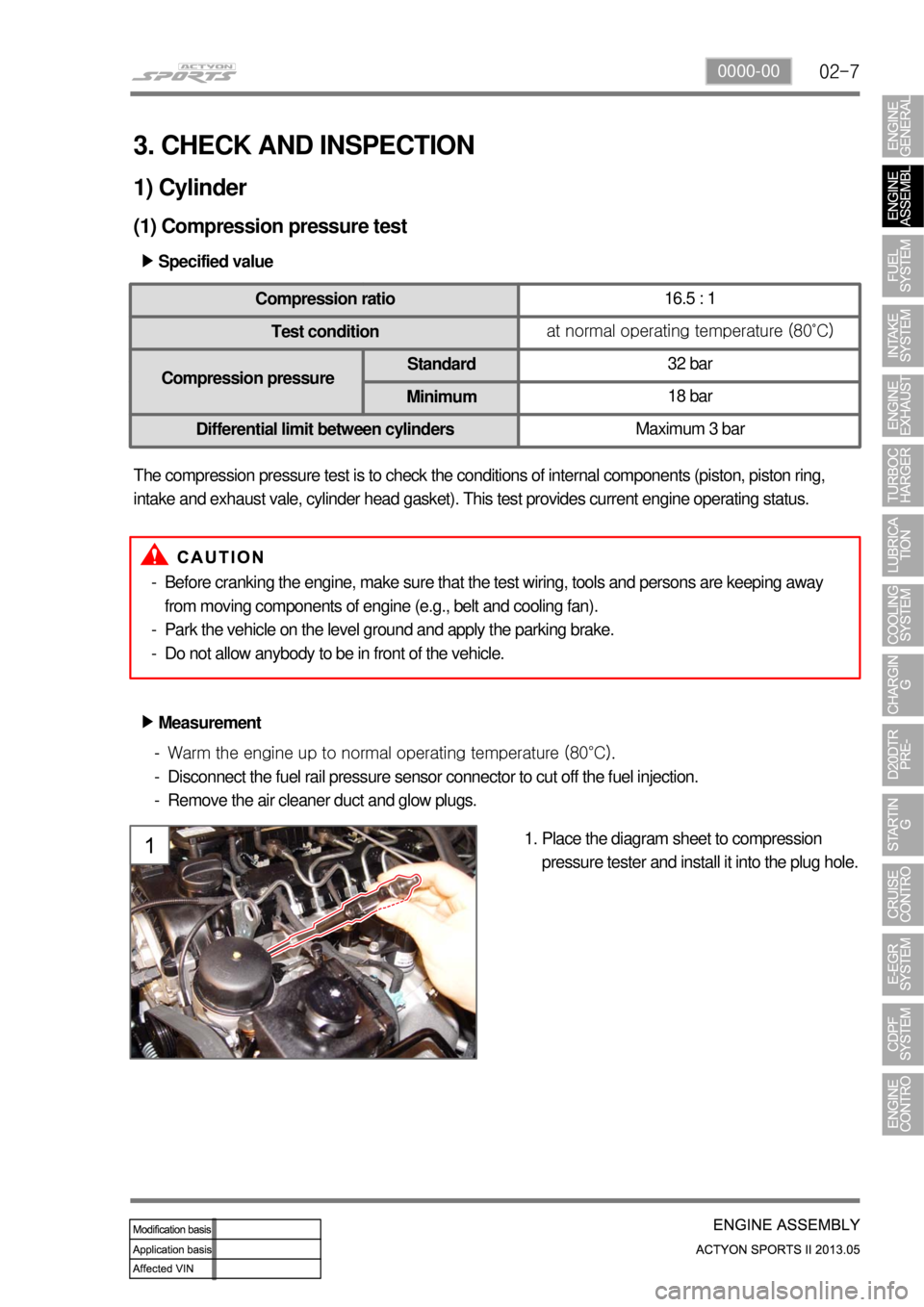
Place the diagram sheet to compression
pressure tester and install it into the plug hole. 1.
Page 55 of 751

02-24
Intake/exhaust CamshaftsFinger follower & HLACamshaft sprocket
Cylinder head gasket
Vacuum pump driveHP pump drive gearCamshaft position sensor
Components ▶
Cylinder head
Cylinder head contains cam position sensor, vacuum pump, intake manifold, exhaust manifold and valve
assembly. Vacuum pump and the high pressure (HP) pump are driven by Camshaft and valves are install
in vertical direction. This enables the compact layout in cylinder head assembly.
6. CYLINDER HEAD
Page 77 of 751
02-46
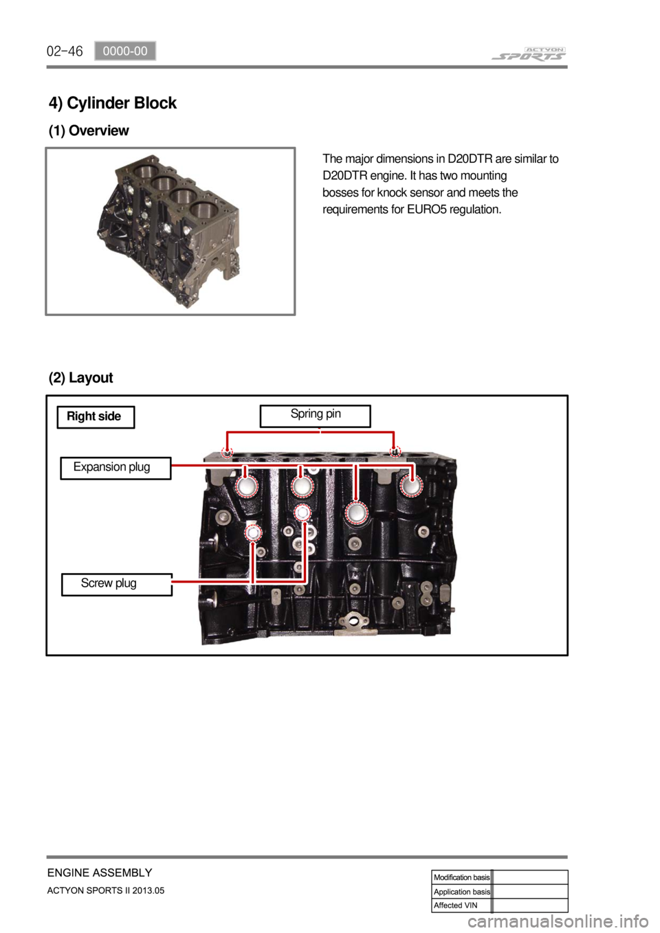
4) Cylinder Block
(1) Overview
The major dimensions in D20DTR are similar to
D20DTR engine. It has two mounting
bosses for knock sensor and meets the
requirements for EURO5 regulation.
(2) Layout
Right sideSpring pin
Expansion plug
Screw plug
Page 89 of 751
03-12
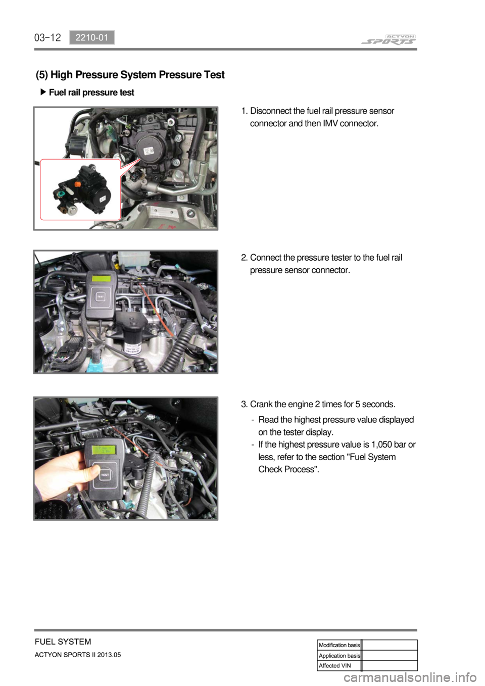
(5) High Pressure System Pressure Test
Fuel rail pressure test ▶
Disconnect the fuel rail pressure sensor
connector and then IMV connector. 1.
Connect the pressure tester to the fuel rail
pressure sensor connector. 2.
Crank the engine 2 times for 5 seconds. 3.
Read the highest pressure value displayed
on the tester display.
If the highest pressure value is 1,050 bar or
less, refer to the section "Fuel System
Check Process". -
-
Page 92 of 751
03-152210-01
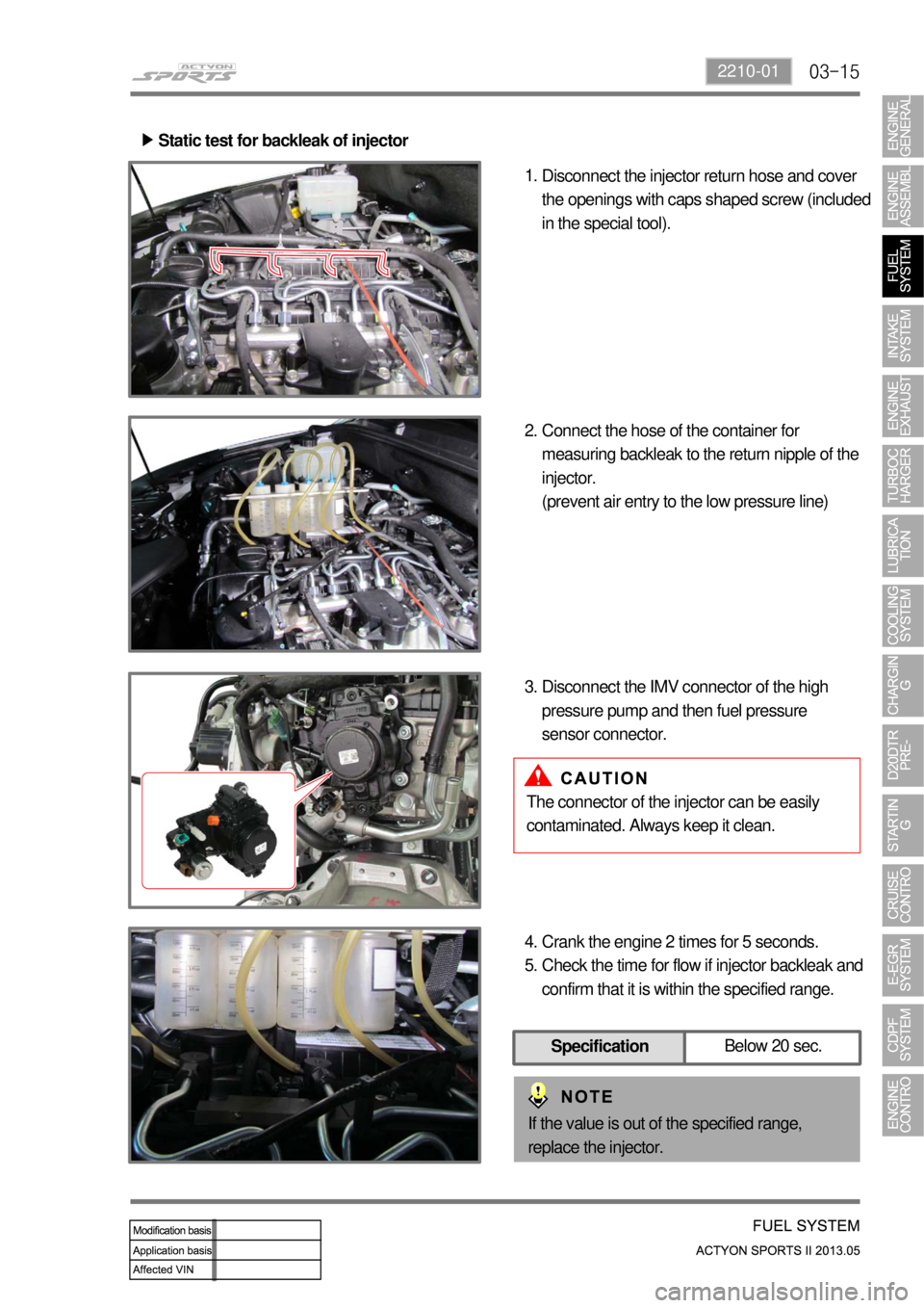
Static test for backleak of injector ▶
Disconnect the injector return hose and cover
the openings with caps shaped screw (included
in the special tool). 1.
Connect the hose of the container for
measuring backleak to the return nipple of the
injector.
(prevent air entry to the low pressure line) 2.
Disconnect the IMV connector of the high
pressure pump and then fuel pressure
sensor connector. 3.
The connector of the injector can be easily
contaminated. Always keep it clean.
Crank the engine 2 times for 5 seconds.
Check the time for flow if injector backleak and
confirm that it is within the specified range. 4.
5.
If the value is out of the specified range,
replace the injector.
SpecificationBelow 20 sec.
Page 94 of 751
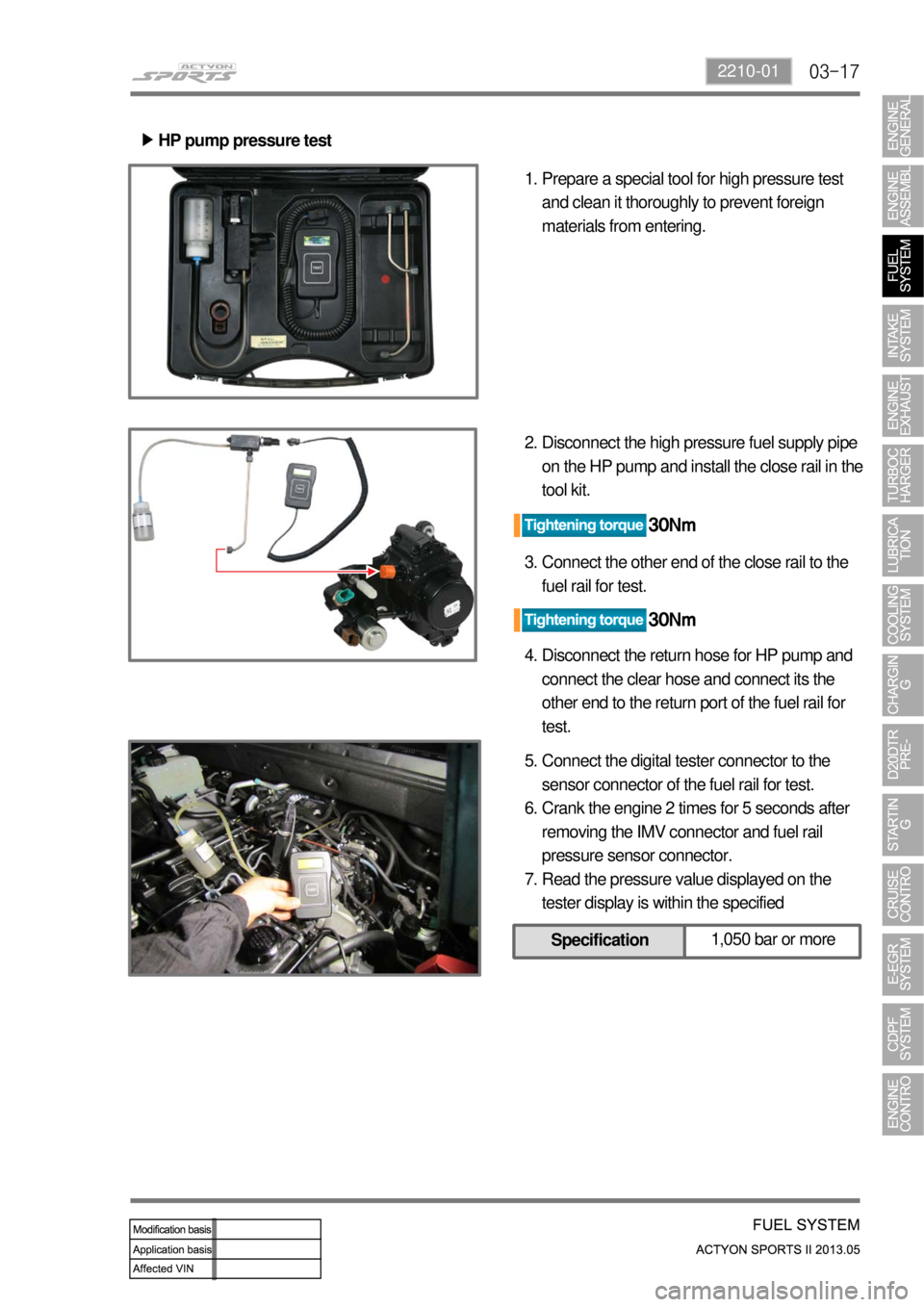
03-172210-01
HP pump pressure test ▶
Prepare a special tool for high pressure test
and clean it thoroughly to prevent foreign
materials from entering. 1.
Disconnect the high pressure fuel supply pipe
on the HP pump and install the close rail in the
tool kit. 2.
Connect the other end of the close rail to the
fuel rail for test. 3.
Disconnect the return hose for HP pump and
connect the clear hose and connect its the
other end to the return port of the fuel rail for
test. 4.
Connect the digital tester connector to the
sensor connector of the fuel rail for test.
Crank the engine 2 times for 5 seconds after
removing the IMV connector and fuel rail
pressure sensor connector.
Read the pressure value displayed on the
tester display is within the specified 5.
6.
7.
Specification1,050 bar or more
Page 98 of 751
03-212210-01
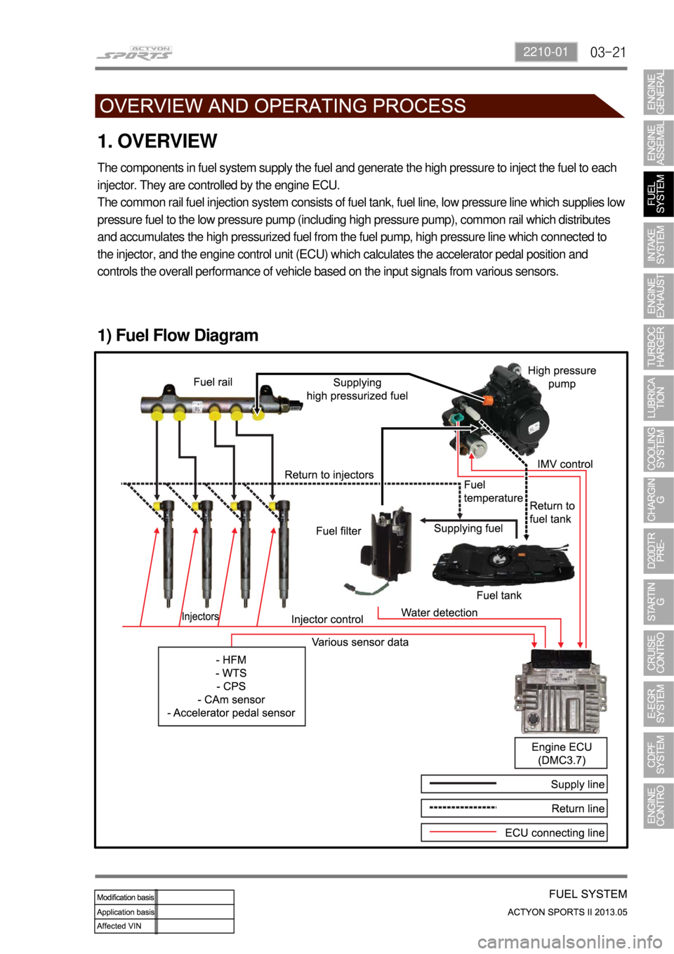
1. OVERVIEW
The components in fuel system supply the fuel and generate the high pressure to inject the fuel to each
injector. They are controlled by the engine ECU.
The common rail fuel injection system consists of fuel tank, fuel line, low pressure line which supplies lo
w
pressure fuel to the low pressure pump (including high pressure pump), common rail which distributes
and accumulates the high pressurized fuel from the fuel pump, high pressure line which connected to
the injector, and the engine control unit (ECU) which calculates the accelerator pedal position and
controls the overall performance of vehicle based on the input signals from various sensors.
1) Fuel Flow Diagram
Page 99 of 751
03-22
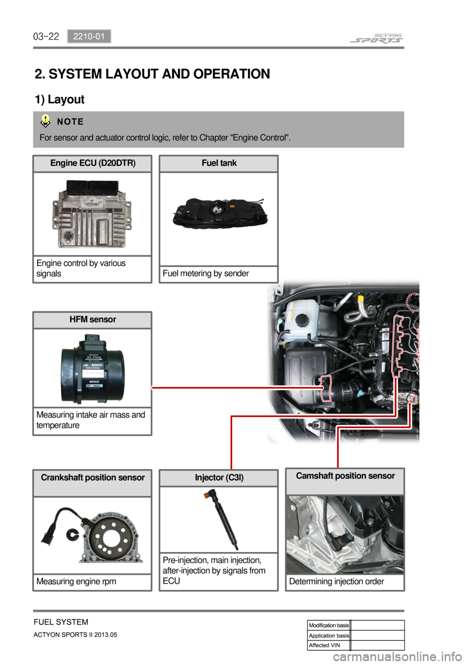
2. SYSTEM LAYOUT AND OPERATION
1) Layout
For sensor and actuator control logic, refer to Chapter "Engine Control".
Engine ECU (D20DTR)
Engine control by various
signalsFuel tank
Fuel metering by sender
HFM sensor
Measuring intake air mass and
temperature
Crankshaft position sensor
Measuring engine rpmInjector (C3I)
Pre-injection, main injection,
after-injection by signals from
ECUCamshaft position sensor
Determining injection order
Page 100 of 751
03-232210-01
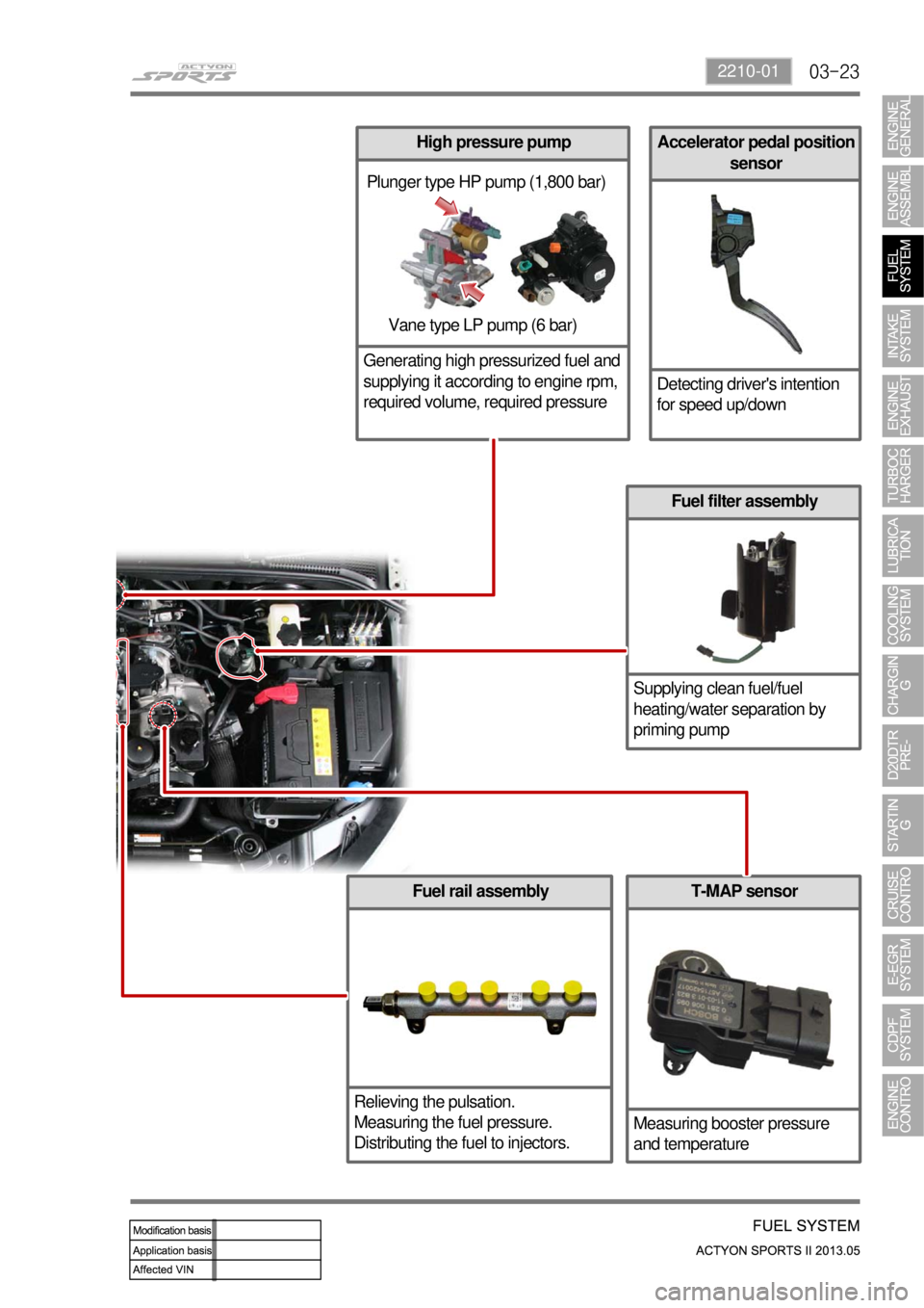
Accelerator pedal position
sensor
Detecting driver's intention
for speed up/down
Fuel rail assembly
Relieving the pulsation.
Measuring the fuel pressure.
Distributing the fuel to injectors.
Fuel filter assembly
Supplying clean fuel/fuel
heating/water separation by
priming pump
Plunger type HP pump (1,800 bar)
Vane type LP pump (6 bar)
T-MAP sensor
Measuring booster pressure
and temperature
High pressure pump
Generating high pressurized fuel and
supplying it according to engine rpm,
required volume, required pressure
Page 101 of 751
03-24
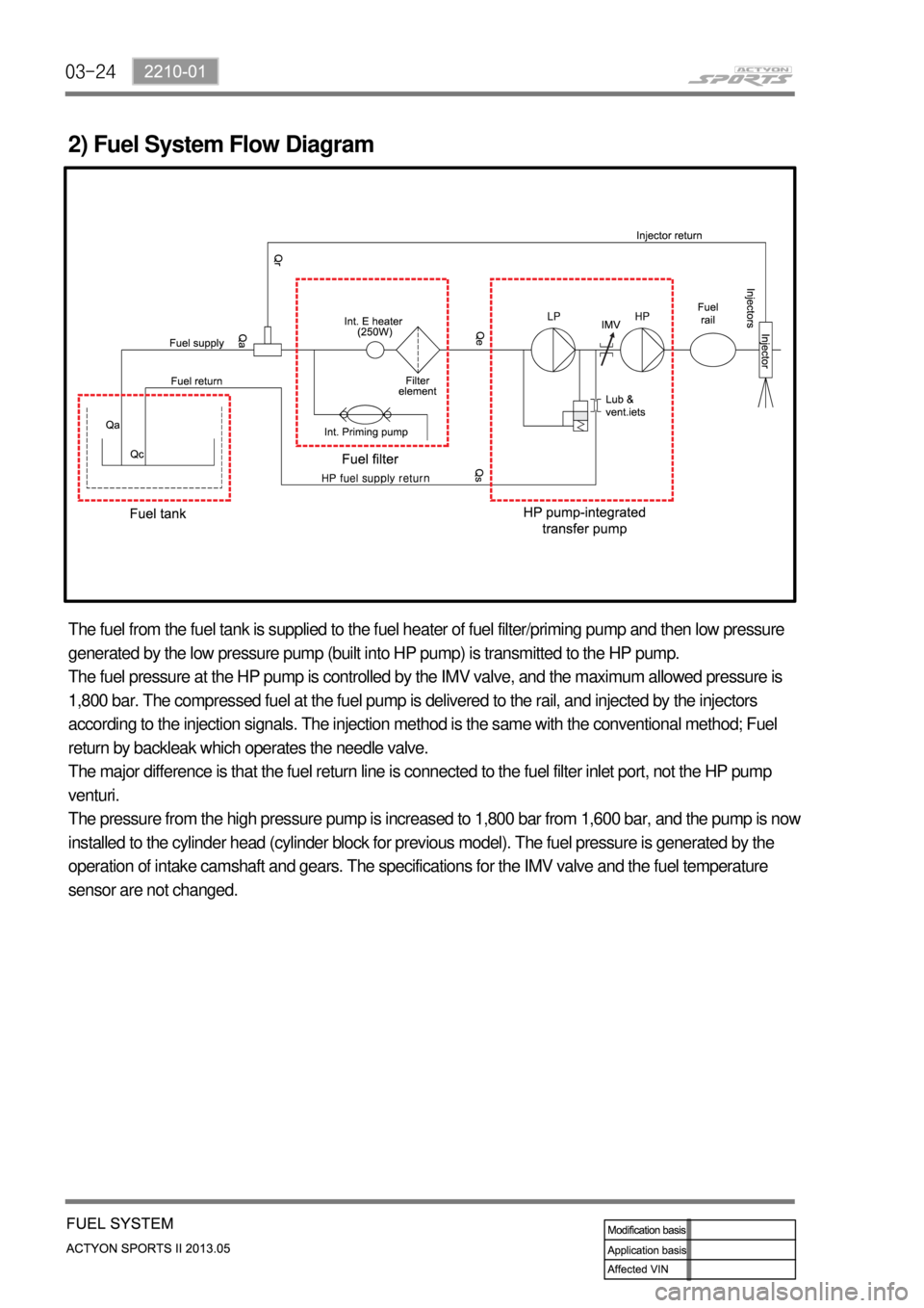
2) Fuel System Flow Diagram
The fuel from the fuel tank is supplied to the fuel heater of fuel filter/priming pump and then low pressure
generated by the low pressure pump (built into HP pump) is transmitted to the HP pump.
The fuel pressure at the HP pump is controlled by the IMV valve, and the maximum allowed pressure is
1,800 bar. The compressed fuel at the fuel pump is delivered to the rail, and injected by the injectors
according to the injection signals. The injection method is the same with the conventional method; Fuel
return by backleak which operates the needle valve.
The major difference is that the fuel return line is connected to the fuel filter inlet port, not the HP pump
venturi.
The pressure from the high pressure pump is increased to 1,800 bar from 1,600 bar, and the pump is now
installed to the cylinder head (cylinder block for previous model). The fuel pressure is generated by the
operation of intake camshaft and gears. The specifications for the IMV valve and the fuel temperature
sensor are not changed.