weight SSANGYONG NEW ACTYON SPORTS 2013 User Guide
[x] Cancel search | Manufacturer: SSANGYONG, Model Year: 2013, Model line: NEW ACTYON SPORTS, Model: SSANGYONG NEW ACTYON SPORTS 2013Pages: 751, PDF Size: 72.63 MB
Page 547 of 751
08-10
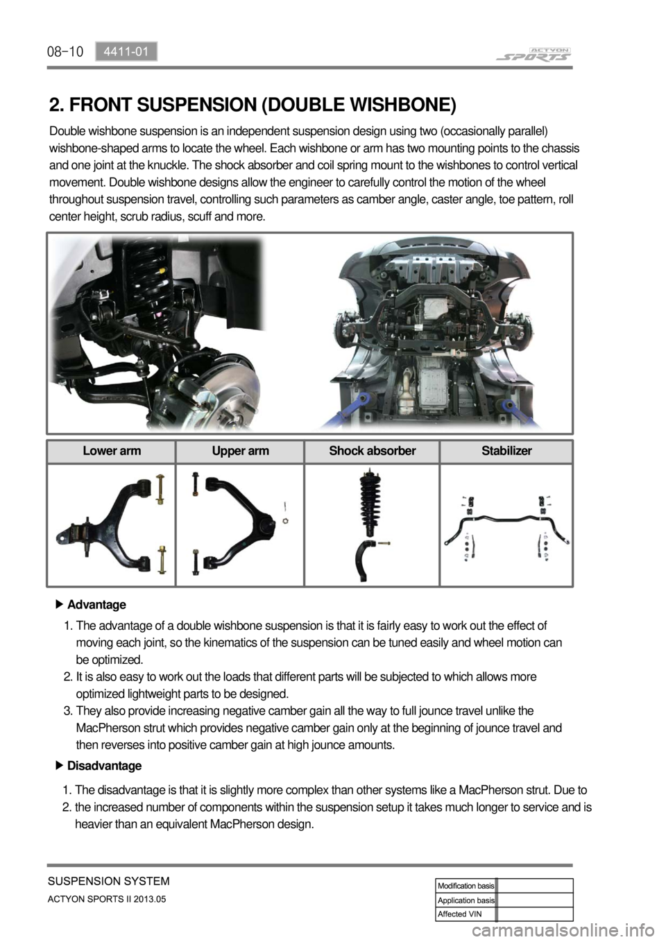
2. FRONT SUSPENSION (DOUBLE WISHBONE)
Advantage ▶
The advantage of a double wishbone suspension is that it is fairly easy to work out the effect of
moving each joint, so the kinematics of the suspension can be tuned easily and wheel motion can
be optimized.
It is also easy to work out the loads that different parts will be subjected to which allows more
optimized lightweight parts to be designed.
They also provide increasing negative camber gain all the way to full jounce travel unlike the
MacPherson strut which provides negative camber gain only at the beginning of jounce travel and
then reverses into positive camber gain at high jounce amounts. 1.
2.
3.
Disadvantage ▶
The disadvantage is that it is slightly more complex than other systems like a MacPherson strut. Due to
the increased number of components within the suspension setup it takes much longer to service and is
heavier than an equivalent MacPherson design. 1.
2. Double wishbone suspension is an independent suspension design using two (occasionally parallel)
wishbone-shaped arms to locate the wheel. Each wishbone or arm has two mounting points to the chassis
and one joint at the knuckle. The shock absorber and coil spring mount to the wishbones to control vertical
movement. Double wishbone designs allow the engineer to carefully control the motion of the wheel
throughout suspension travel, controlling such parameters as camber angle, caster angle, toe pattern, roll
center height, scrub radius, scuff and more.
Lower arm Upper arm Shock absorber Stabilizer
Page 548 of 751
08-114411-01
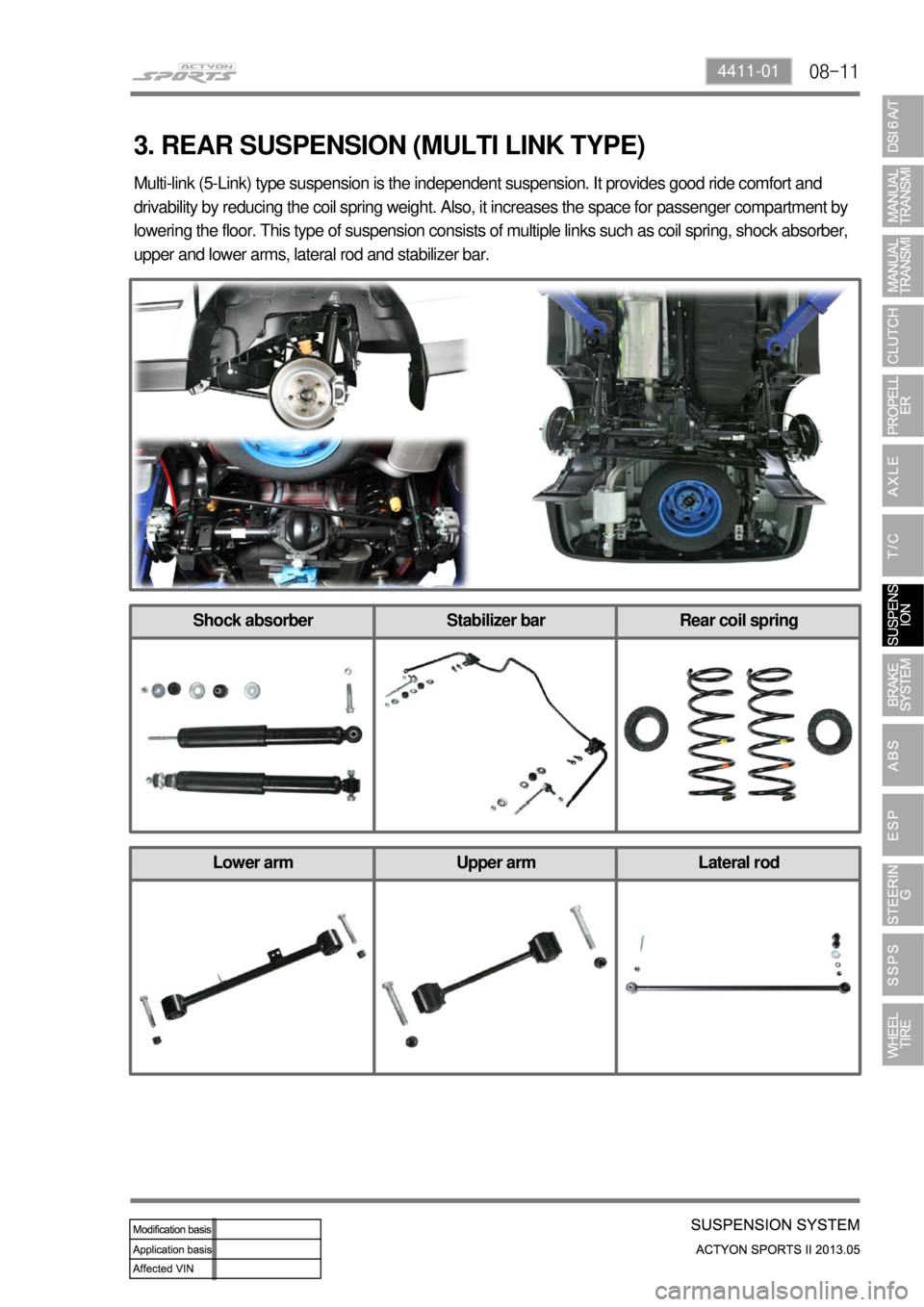
3. REAR SUSPENSION (MULTI LINK TYPE)
Multi-link (5-Link) type suspension is the independent suspension. It provides good ride comfort and
drivability by reducing the coil spring weight. Also, it increases the space for passenger compartment by
lowering the floor. This type of suspension consists of multiple links such as coil spring, shock absorber,
upper and lower arms, lateral rod and stabilizer bar.
Shock absorber Stabilizer bar Rear coil spring
Lower arm Upper arm Lateral rod
Page 594 of 751
10-14
2) Basic Theory of ABS Function
To give you a better understanding of the tasks and functions of ABS, we will first look at the physics
principles.
(1) Stopping distance
(2) Brake force on a wheel
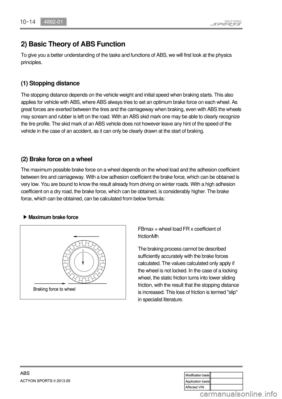
The maximum possible brake force on a wheel depends on the wheel load and the adhesion coefficient
between tire and carriageway. With a low adhesion coefficient the brake force, which can be obtained is
very low. You are bound to know the result already from driving on winter roads. With a high adhesion
coefficient on a dry road, the brake force, which can be obtained, is considerably higher. The brake
force, which can be obtained, can be calculated from below formula:
Maximum brake force ▶
FBmax = wheel load FR x coefficient of
frictionMh
The braking process cannot be described
sufficiently accurately with the brake forces
calculated. The values calculated only apply if
the wheel is not locked. In the case of a locking
wheel, the static friction turns into lower sliding
friction, with the result that the stopping distance
is increased. This loss of friction is termed "slip"
in specialist literature.
The stopping distance depends on the vehicle weight and initial speed when braking starts. This also
applies for vehicle with ABS, where ABS always tries to set an optimum brake force on each wheel. As
great forces are exerted between the tires and the carriageway when braking, even with ABS the wheels
may scream and rubber is left on the road. With an ABS skid mark one may be able to clearly recognize
the tire profile. The skid mark of an ABS vehicle does not however leave any hint of the speed of the
vehicle in the case of an accident, as it can only be clearly drawn at the start of braking.
Page 653 of 751

13-34620-01
1. SPECIFICATIONS
Item Item Specification
SSPS solenoid valveRated voltage DC 12 V
Rated voltage 1.0 A
Resistance6.7 ±1 Ω
Power steering oil pump
(with SSPS)Operating temperature-40℃~150℃
Release pressure 90 bar
Displacement 9.3 cc/rev
Flow velocity 9.75~6 l/mn
Pulley sizeØ115
Pulley type 6 groove
Housing material Aluminium
Power steering fluid reservoir
(with SSPS)Fracture pressuremin 8kgf/㎠
Air leakage2 kgf/㎠×min
Cap open torque 9.8 to 14.2 Nm
Oil capacity FULL 550cc
Power steering gear box
(with SSPS)Gear type Rack & pinion type
Gear ratio 40.245
Fixed rack 3.78
Gear weight 12.800 kg
Steering angleInner36.2°
Outer32.4°
Page 664 of 751
14-34170-09
1. SPECIFICATIONS
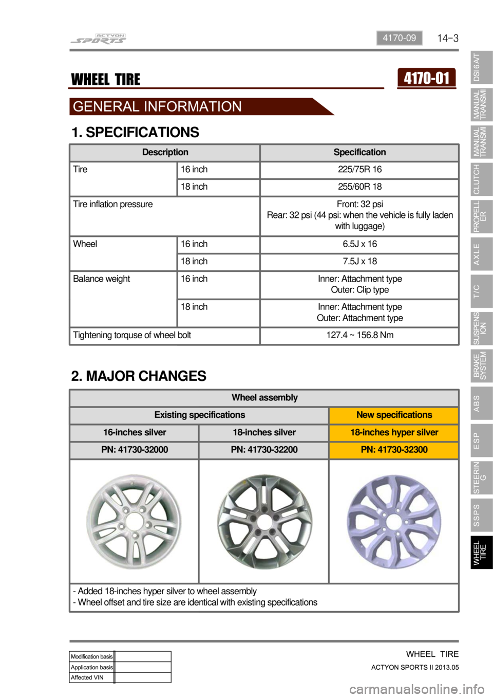
2. MAJOR CHANGES
Wheel assembly
16-inches silver 18-inches silver 18-inches hyper silver
PN: 41730-32000 PN: 41730-32200 PN: 41730-32300
- Added 18-inches hyper silver to wheel assembly
- Wheel offset and tire size are identical with existing specifications
Existing specifications New specifications
Description Specification
Tire 16 inch 225/75R 16
18 inch 255/60R 18
Tire inflation pressure Front: 32 psi
Rear: 32 psi (44 psi: when the vehicle is fully laden
with luggage)
Wheel 16 inch 6.5J x 16
18 inch 7.5J x 18
Balance weight 16 inch Inner: Attachment type
Outer: Clip type
18 inch Inner: Attachment type
Outer: Attachment type
Tightening torquse of wheel bolt 127.4 ~ 156.8 Nm
Page 670 of 751

14-94170-09
Wheel balance 5.
Check the wheel balance when the wheel
is unbalanced or the tire is repaired.
The total weight of the wheel weight
should not exceed 150 g.
Ensure that the balance weight installed is
not projected over 3mm from the wheel
surface.
Use the specified aluminum wheel balance
weights for aluminum wheels.
Weight balance can be added by 5 g.
There are two types of weight balance,
tape type and adhesion type. -
-
-
-
-
-
Make sure to read the manual of the
manufacturer thoroughly before using
wheel balance tester. -
Change tire location
To avoid uneven wear of tires and to prolong
tire life, inspect and rotate your tires every
5,000 km. 6.
Mixing tires could cause to lose control while driving. Be sure to use the same size and type tires of
the same manufacturer on all wheels. -
Page 672 of 751
14-114170-09
1. OVERVIEW
A radial tire uses a cord angle of 90 degrees. That is, the cord material runs in a radial or direct line from
one bead to the other across the tread. In addition, a radial tire has a belt overwrap under the tread
surface to provide greater structural stability. The belt overwrap of a radial tire distortion while the radial
structure enables high speed driving.
Tire supports the weight of the vehicle, reduces the impact from the road and at the same time, transmits
<009b008f008c004700970096009e008c00990047009b009600470097009900960097008c0093005300470089009900880092008c004700880095008b0047009a009b008c008c00990047009600950047009b008f008c0047009900960088008b0055004700
70009b004700880093009a00960047008d009c0095008a009b>ions to maintain a vehicle’s
movement. In order to complete such tasks, a tire must be structured to be a resilient vessel of air.
There is wear limit mark on the tire, which protrudes as a strip shape located approximately 1.6 mm from
the groove bottom. This wear limit mark is not seen from the outside so there is additional "▲"
mark on the shoulder to let the driver find the wear mark easily. To measure the tire groove depth,
measure at any point other than the point which has a wear limit mark.
The tire is worn unevenly according to the driver's driving habit, improper servicing, low tire inflation
pressure, changed tire location, etc.
Page 678 of 751

14-174170-09
If weight is not equally distributed around the wheel, unbalance centrifugal force by the wheel rotation
produces vibration. As the centrifugal force is produced proportional to the square of the rotating speed,
the wheel weight should be balanced even at high speed. There are two types of the tire and wheel
balancing: static and dynamic. Abnormal vibration may also occur due to unbalanced rigidity or size of
tires.
Static Balance ▶
When the free rotation of the wheel is allowed,
the heavier part is stopped on the bottom if the
wheel weight is unbalanced and this is called
"Static Unbalance". Also, the state at which tire's
stop position is not same is called "Static
Balance" when the wheel is rotated again. If the
part A is heavier as shown in the figure 1, add
the balance weight of a weight corresponding to
unbalanced weight from B to A to maintain the
static balance. If the static balance is not
maintained, tramping, up and down vibration of
the wheels, occurs.
Dynamic Balance ▶
The static unbalance of the wheel creates the
vibration in the vertical direction, but the dynamic
unbalance creates the vibration in the lateral
direction. As shown in the figure 2 (a), if two
parts, (2) and (3), are heavier when the wheels
are under the static balance condition, dynamic
unbalance is created, resulting in shimmy, left
and right vibration of the wheels, and the torque
Fxa is applied in the axial direction. To correct
the dynamic unbalance, add the balance weight
of a same weight for two points of the
circumference of the rim, A and B, as shown in
the figure 2 (b), and apply the torque in the
opposite direction to the torque Fxa to offset in
order to ensure smooth rotation of the wheel.
Center
A
B
(a) (b)
[Figure 1]
[Figure 2]
3. WHEEL BALANCE
Page 679 of 751
14-18
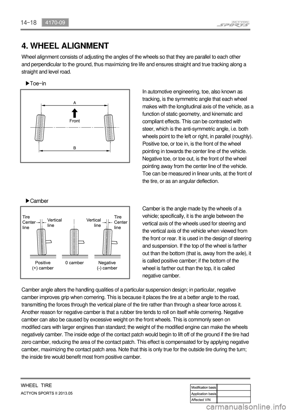
4. WHEEL ALIGNMENT
▶Toe-in
▶Camber
In automotive engineering, toe, also known as
tracking, is the symmetric angle that each wheel
makes with the longitudinal axis of the vehicle, as a
function of static geometry, and kinematic and
compliant effects. This can be contrasted with
steer, which is the anti-symmetric angle, i.e. both
wheels point to the left or right, in parallel (roughly).
Positive toe, or toe in, is the front of the wheel
pointing in towards the center line of the vehicle.
Negative toe, or toe out, is the front of the wheel
pointing away from the center line of the vehicle.
Toe can be measured in linear units, at the front of
the tire, or as an angular deflection.
Camber is the angle made by the wheels of a
vehicle; specifically, it is the angle between the
vertical axis of the wheels used for steering and
the vertical axis of the vehicle when viewed from
the front or rear. It is used in the design of steering
and suspension. If the top of the wheel is farther
out than the bottom (that is, away from the axle), it
is called positive camber; if the bottom of the
wheel is farther out than the top, it is called
negative camber. Wheel alignment consists of adjusting the angles of the wheels so that they are parallel to each other
and perpendicular to the ground, thus maximizing tire life and ensures straight and true tracking along a
straight and level road.
Camber angle alters the handling qualities of a particular suspension design; in particular, negative
camber improves grip when cornering. This is because it places the tire at a better angle to the road,
transmitting the forces through the vertical plane of the tire rather than through a shear force across it.
Another reason for negative camber is that a rubber tire tends to roll on itself while cornering. Negative
camber can also be caused by excessive weight on the front wheels. This is commonly seen on
modified cars with larger engines than standard; the weight of the modified engine can make the wheels
negatively camber. The inside edge of the contact patch would begin to lift off of the ground if the tire had
zero camber, reducing the area of the contact patch. This effect is compensated for by applying negative
camber, maximizing the contact patch area. Note that this is only true for the outside tire during the turn;
the inside tire would benefit most from positive camber.
Page 681 of 751

14-20
Even friction coefficient road Uneven friction coefficient road
Driving Force
Braking Force
Supporting the Vehicle Weight ▶Transferring the Driving Force & Braking Force to Road ▶
5. FUNCTIONS OF TIRE
Supporting the Vehicle Weight ▶