Fuel sensor SSANGYONG NEW ACTYON SPORTS 2013 Owner's Manual
[x] Cancel search | Manufacturer: SSANGYONG, Model Year: 2013, Model line: NEW ACTYON SPORTS, Model: SSANGYONG NEW ACTYON SPORTS 2013Pages: 751, PDF Size: 72.63 MB
Page 221 of 751
15-210000-00
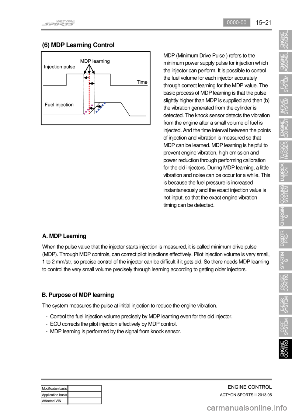
MDP (Minimum Drive Pulse ) refers to the
minimum power supply pulse for injection which
the injector can perform. It is possible to control
the fuel volume for each injector accurately
through correct learning for the MDP value. The
basic process of MDP learning is that the pulse
slightly higher than MDP is supplied and then (b)
the vibration generated from the cylinder is
detected. The knock sensor detects the vibration
from the engine after a small volume of fuel is
injected. And the time interval between the points
of injection and vibration is measured so that
MDP can be learned. MDP learning is helpful to
prevent engine vibration, high emission and
power reduction through performing calibration
for the old injectors. During MDP learning, a little
vibration and noise can be occur for a while. This
is because the fuel pressure is increased
instantaneously and the exact injection value is
not input, so that the exact engine vibration
timing can be detected.
(6) MDP Learning Control
A. MDP Learning
When the pulse value that the injector starts injection is measured, it is called minimum drive pulse
(MDP). Through MDP controls, can correct pilot injections effectively. Pilot injection volume is very small,
1 to 2 mm/str, so precise control of the injector can be difficult if it gets old. So there needs MDP learning
to control the very small volume precisely through learning according to getting older injectors.
Control the fuel injection volume precisely by MDP learning even for the old injector.
ECU corrects the pilot injection effectively by MDP control.
MDP learning is performed by the signal from knock sensor. -
-
- The system measures the pulse at initial injection to reduce the engine vibration.
B. Purpose of MDP learning
Page 223 of 751
15-230000-00
(7) Knocking Control
A. Resetting the pilot injection
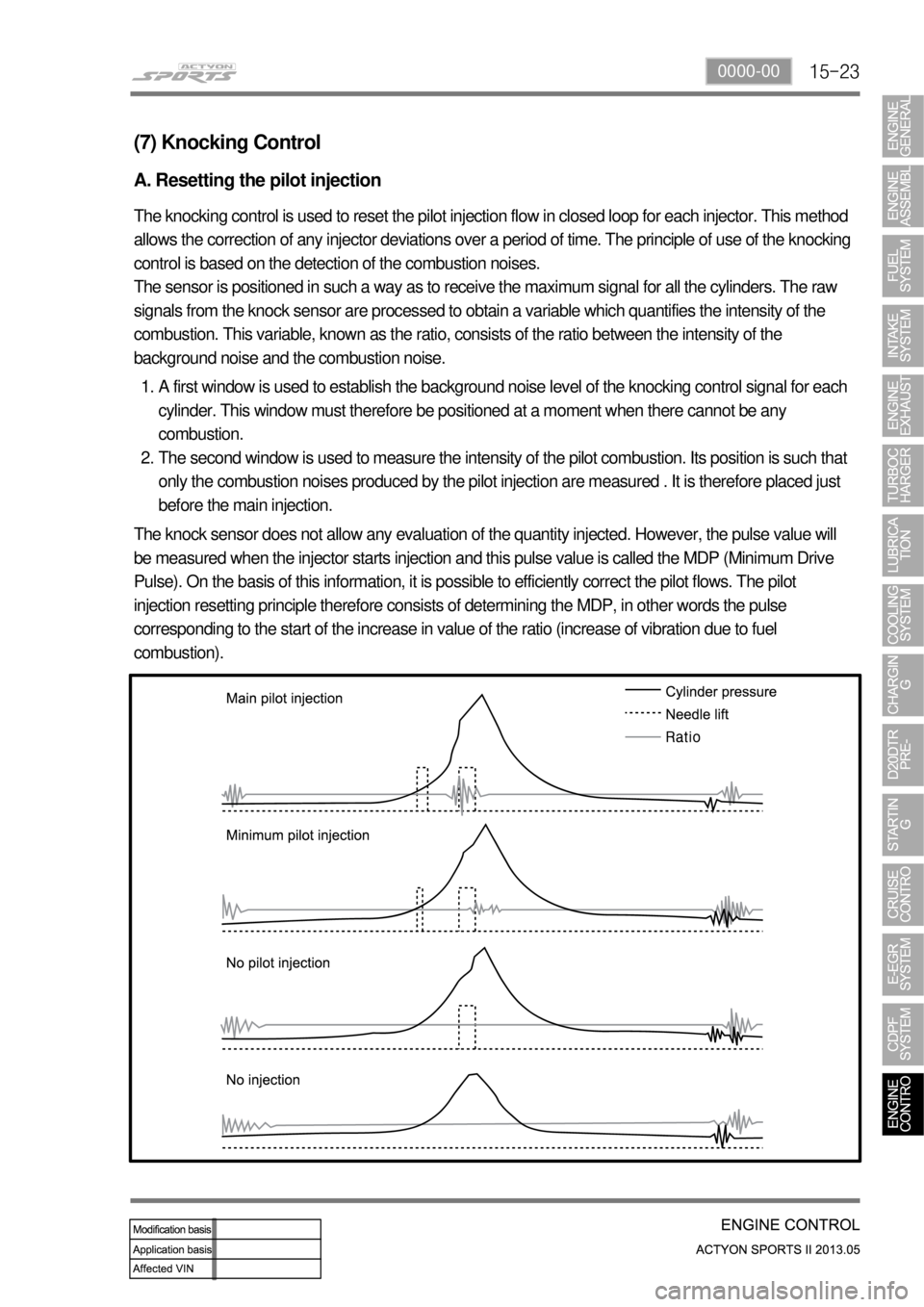
The knocking control is used to reset the pilot injection flow in closed loop for each injector. This method
allows the correction of any injector deviations over a period of time. The principle of use of the knocking
control is based on the detection of the combustion noises.
The sensor is positioned in such a way as to receive the maximum signal for all the cylinders. The raw
signals from the knock sensor are processed to obtain a variable which quantifies the intensity of the
combustion. This variable, known as the ratio, consists of the ratio between the intensity of the
background noise and the combustion noise.
A first window is used to establish the background noise level of the knocking control signal for each
cylinder. This window must therefore be positioned at a moment when there cannot be any
combustion.
The second window is used to measure the intensity of the pilot combustion. Its position is such that
only the combustion noises produced by the pilot injection are measured . It is therefore placed just
before the main injection. 1.
2.
The knock sensor does not allow any evaluation of the quantity injected. However, the pulse value will
be measured when the injector starts injection and this pulse value is called the MDP (Minimum Drive
Pulse). On the basis of this information, it is possible to efficiently correct the pilot flows. The pilot
injection resetting principle therefore consists of determining the MDP, in other words the pulse
corresponding to the start of the increase in value of the ratio (increase of vibration due to fuel
combustion).
Page 224 of 751
15-24
This is done periodically under certain operating conditions. When the resetting is finished, the new
minimum pulse value replaces the value obtained during the previous resetting. The first MDP value is
provided by the C3I. Each resetting then allows the closed loop of the MDP to be updated according to
the deviation of the injector.
B. Detection of leaks in the cylinders
The accelerometer is also used to detect any injector which may have stuck open. The detection
principle is based on monitoring the ratio. If there is a leak in the cylinder, the accumulated fuel self-
ignites as soon as the temperature and pressure conditions are favorable (high engine speed, high load
and small leak).
This combustion is set off at about 20 degrees before TDC and before main injection.
The ratio therefore increases considerably in the detection window. It is this increase which allows the
leaks to be detected. The threshold beyond which a fault is signaled is a percentage of the maximum
possible value of the ratio.
Because of the severity of the recovery process (engine shut-down), the etection must be extremely
robust.
An increase in the ratio can be the consequence of various causes:
Pilot injection too much
Main combustion offset
Fuel leak in the cylinder -
-
-
If the ratio becomes too high, the strategy initially restricts the pilot injection flow and retards the main
injection. If the ratio remains high despite these interventions, this shows that a real leak is present, a
fault is signaled and the engine is shut down.
C. Detection of an accelerometer fault
This strategy permits the detection of a fault in the sensor or in the wiring loom connecting the sensor to
the ECU.
It is based on detection of the combustion. When the engine is idling, the detection window is set too low
for the combustion caused by the main injection. If the ratio increases, this shows that the knock sensor
is working properly, but otherwise a fault is signaled to indicate a sensor failure. The recovery modes
associated with this fault consist of inhibition of the pilot injection and discharge through the injectors.
Page 225 of 751
15-250000-00
(8) Swirl control
A. Overview
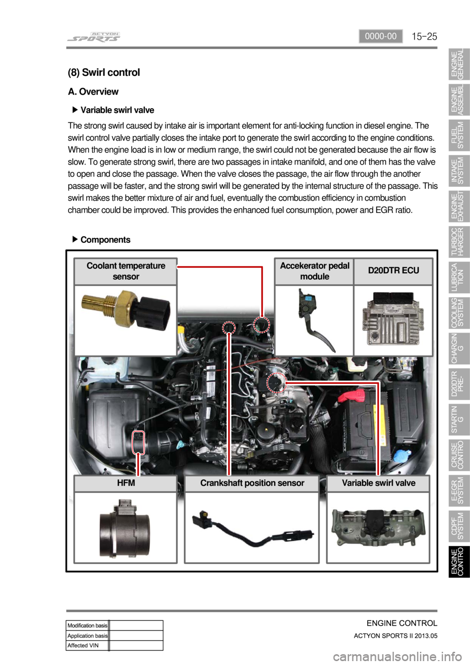
Variable swirl valve ▶
The strong swirl caused by intake air is important element for anti-locking function in diesel engine. The
swirl control valve partially closes the intake port to generate the swirl according to the engine conditions.
When the engine load is in low or medium range, the swirl could not be generated because the air flow is
slow. To generate strong swirl, there are two passages in intake manifold, and one of them has the valve
to open and close the passage. When the valve closes the passage, the air flow through the another
passage will be faster, and the strong swirl will be generated by the internal structure of the passage. This
swirl makes the better mixture of air and fuel, eventually the combustion efficiency in combustion
chamber could be improved. This provides the enhanced fuel consumption, power and EGR ratio.
Components ▶
HFMCrankshaft position sensorVariable swirl valve
Coolant temperature
sensorAccekerator pedal
moduleD20DTR ECU
Page 236 of 751
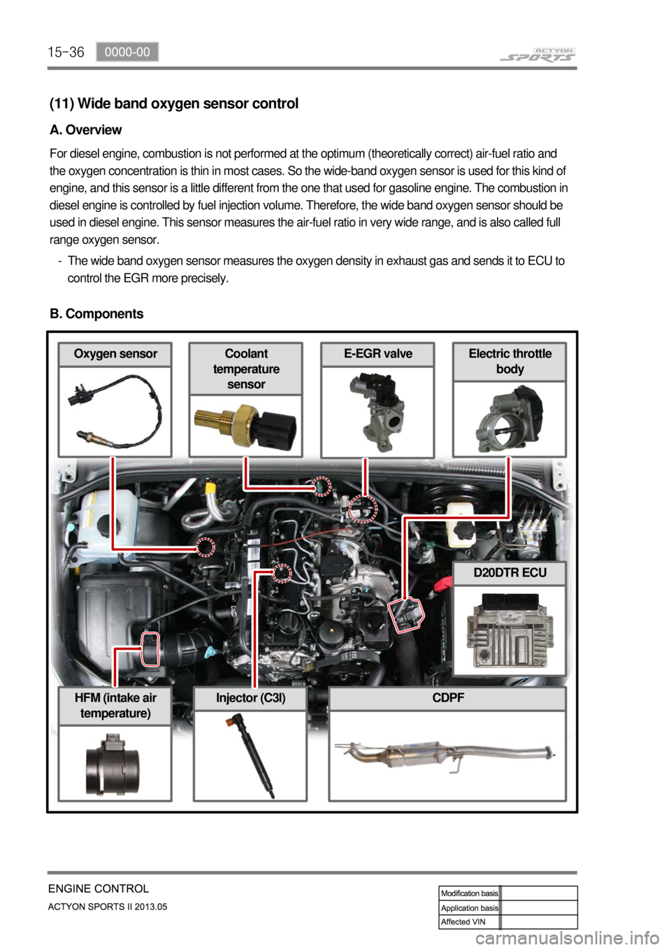
15-36
HFM (intake air
temperature)CDPF
Electric throttle
bodyCoolant
temperature
sensorOxygen sensor
Injector (C3I)
E-EGR valve
(11) Wide band oxygen sensor control
A. Overview
For diesel engine, combustion is not performed at the optimum (theoretically correct) air-fuel ratio and
the oxygen concentration is thin in most cases. So the wide-band oxygen sensor is used for this kind of
engine, and this sensor is a little different from the one that used for gasoline engine. The combustion in
diesel engine is controlled by fuel injection volume. Therefore, the wide band oxygen sensor should be
used in diesel engine. This sensor measures the air-fuel ratio in very wide range, and is also called full
range oxygen sensor.
The wide band oxygen sensor measures the oxygen density in exhaust gas and sends it to ECU to
control the EGR more precisely. -
B. Components
D20DTR ECU
Page 249 of 751
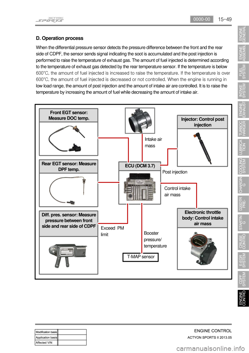
15-490000-00
Diff. pres. sensor: Measure
pressure between front
side and rear side of CDPF
ECU (DCM 3.7)
Injector: Control post
injection
D. Operation process
When the differential pressure sensor detects the pressure difference between the front and the rear
side of CDPF, the sensor sends signal indicating the soot is accumulated and the post injection is
performed to raise the temperature of exhaust gas. The amount of fuel injected is determined according
to the temperature of exhaust gas detected by the rear temperature sensor. If the temperature is below
600°C, the amount of fuel injected is increased to raise the tem
perature. If the temperature is over
600°C, the amount of fuel injected is decreased or not controlled. When the engine is running in
low load range, the amount of post injection and the amount of intake air are controlled. It is to raise the
temperature by increasing the amount of fuel while decreasing the amount of intake air.
Front EGT sensor:
Measure DOC temp.
Rear EGT sensor: Measure
DPF temp.
Electronic throttle
body: Control intake
air mass
T-MAP sensor
Intake air
mass
Exceed PM
limitBooster
pressure/
temperaturePost injection
Control intake
air mass
Page 257 of 751
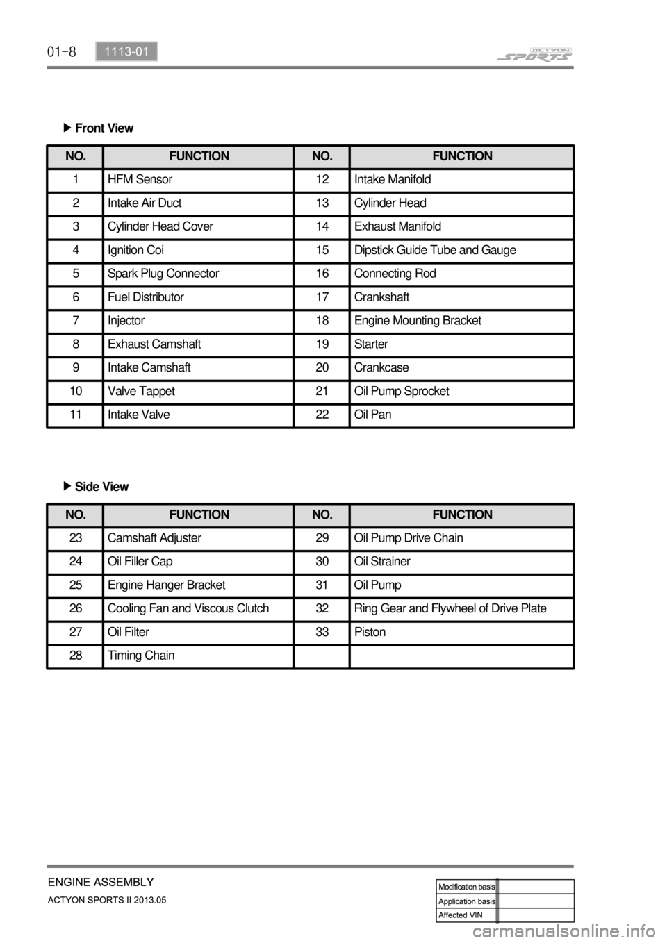
01-8
Front View ▶
NO. FUNCTION NO. FUNCTION
1 HFM Sensor 12 Intake Manifold
2 Intake Air Duct 13 Cylinder Head
3 Cylinder Head Cover 14 Exhaust Manifold
4 Ignition Coi 15 Dipstick Guide Tube and Gauge
5 Spark Plug Connector 16 Connecting Rod
6 Fuel Distributor 17 Crankshaft
7 Injector 18 Engine Mounting Bracket
8 Exhaust Camshaft 19 Starter
9 Intake Camshaft 20 Crankcase
10 Valve Tappet 21 Oil Pump Sprocket
11 Intake Valve 22 Oil Pan
NO. FUNCTION NO. FUNCTION
23 Camshaft Adjuster 29 Oil Pump Drive Chain
24 Oil Filler Cap 30 Oil Strainer
25 Engine Hanger Bracket 31 Oil Pump
26 Cooling Fan and Viscous Clutch 32 Ring Gear and Flywheel of Drive Plate
27 Oil Filter 33 Piston
28 Timing Chain
Side View ▶
Page 274 of 751
02-52211-06
1. FUEL SYSTEM
The function of the fuel metering system is to deliver the correct amount of fuel to the engine under all
operating conditions.
The fuel is delivered to the engine by the individual fuel injectors mounted into the intake manifold nea
r
each cylinder.
The main fuel control sensors are the Mass Air Flow (MAF) sensor and the oxygen (O2) sensors.
The MAF sensor monitors the mass flow of the air being drawn into the engine. An electrically heated
element is mounted in the intake air stream, where it is cooled by the flow of incoming air. Engine Control
Module (ECM) modulates the flow of heating current to maintain the temperature differential between the
heated film and the intake air at a constant level. The amount of heating current required to maintain the
temperature thus provides an index for the mass air flow. This
concept automatically compensates for variations in air density, as this is one of the factors that
determines the amount of warmth that the surrounding air absorbs from the heated element. MAF
sensor is located between the air filter and the throttle valve.
Under high fuel demands, the MAF sensor reads a high mass flow condition, such as wide open throttle.
The ECM uses this information to enrich the mixture, thus increasing the fuel injector on-time, to provide
the correct amount of fuel. When decelerating, the mass flow decreases. This mass flow change is
sensed by the MAF sensor and read by the ECM, which then decreases the fuel injector on-time due to
the low fuel demand conditions.
The O2 sensors are located in the exhaust pipe before catalytic converter. The O2 sensors indicate to
the ECM the amount of oxygen in the exhaust gas, and the ECM changes the air/fuel ratio to the engine
by controlling the fuel injectors. The best air/fuel ratio to minimize exhaust emissions is 14.7 to 1, which
allows the catalytic converter to operate most efficiently. Because
of the constant measuring and adjusting of the air/fuel ratio, the fuel injection system is called a "closed
loop" system.
The ECM uses voltage inputs from several sensors to determine how much fuel to provide to the engine.
The fuel is delivered under one of several conditions, called "modes".
Page 275 of 751
02-6
1) Starting Mode
When the ignition is turned ON, the ECM turns the fuel pump relay on for 1 second. The fuel pump then
builds fuel pressure. The ECM also checks the Engine Coolant Temperature (ECT) sensor and the
Throttle Position (TP) sensor and determines the proper air/fuel ratio for starting the engine. This ranges
from1.5 to 1 at -36 °C (-33 °F) coolant temperature to 14.7 to 1 at 94 °C (201 °F) coolant
temperature. The ECM controls the amountof fuel delivered in the starting mode by changing how long
the fuel injector is turned on and off. This is done by ''pulsing" the fuel injectors for very short times.
2) Run Mode
The run mode has two conditions called ''open loop" and ''closed loop".
3) Open Loop
When the engine is first started and it is above 690 rpm, the system goes into "open loop" operation. In
"open loop", the ECM ignores the signal from the HO2S and calculates the air/fuel ratio based on inputs
from the ECT sensor and the MAF sensor. The ECM stays in "open loop" until the following conditions
are met:
The O2 has a varying voltage output, showing that it is hot enough to operate properly.
The ECT sensor is above a specified temperature (22.5 °C).
A specific amount of time has elapsed after starting the engine. -
-
-
4) Closed Loop
The specific values for the above conditions vary with different engines and are stored in the
Electronically Erasable Programmable Read-Only Memory (EEPROM).
When these conditions are met, the system goes into "closed loop" operation. In "closed loop", the ECM
calculates the air/fuel ratio (fuel injector on- time) based on the signals from the O2 sensors. This allows
the air/fuel ratio to stay very close to 14.7 to 1.
5) Acceleration Mode
The ECM responds to rapid changes in throttle position and airflow and provides extra fuel.
6) Deceleration Mode
The ECM responds to changes in throttle position and airflow and reduces the amount of fuel. When
deceleration is very fast, the ECM can cut off fuel completely for short periods of time.
Page 276 of 751
02-72211-06
7) Battery Voltage Correction Mode
When battery voltage is low, the ECM can compensate for a weak spark delivered by the ignition
module by using the following methods:
Increasing the fuel injector pulse width.
Increasing the idle speed rpm.
Increasing the ignition dwell time. -
-
-
8) Fuel Cut-Off Mode
No fuel is delivered by the fuel injectors when the ignition is off. This prevents dieseling or engine runon.
Also, the fuel is not delivered if there are no reference pulses received from the CKP sensor. This
prevents flooding.