SSANGYONG NEW ACTYON SPORTS 2013 Owner's Manual
NEW ACTYON SPORTS 2013
SSANGYONG
SSANGYONG
https://www.carmanualsonline.info/img/67/57512/w960_57512-0.png
SSANGYONG NEW ACTYON SPORTS 2013 Owner's Manual
Page 442 of 751
Page 454 of 751
01-8
4WD
2WD
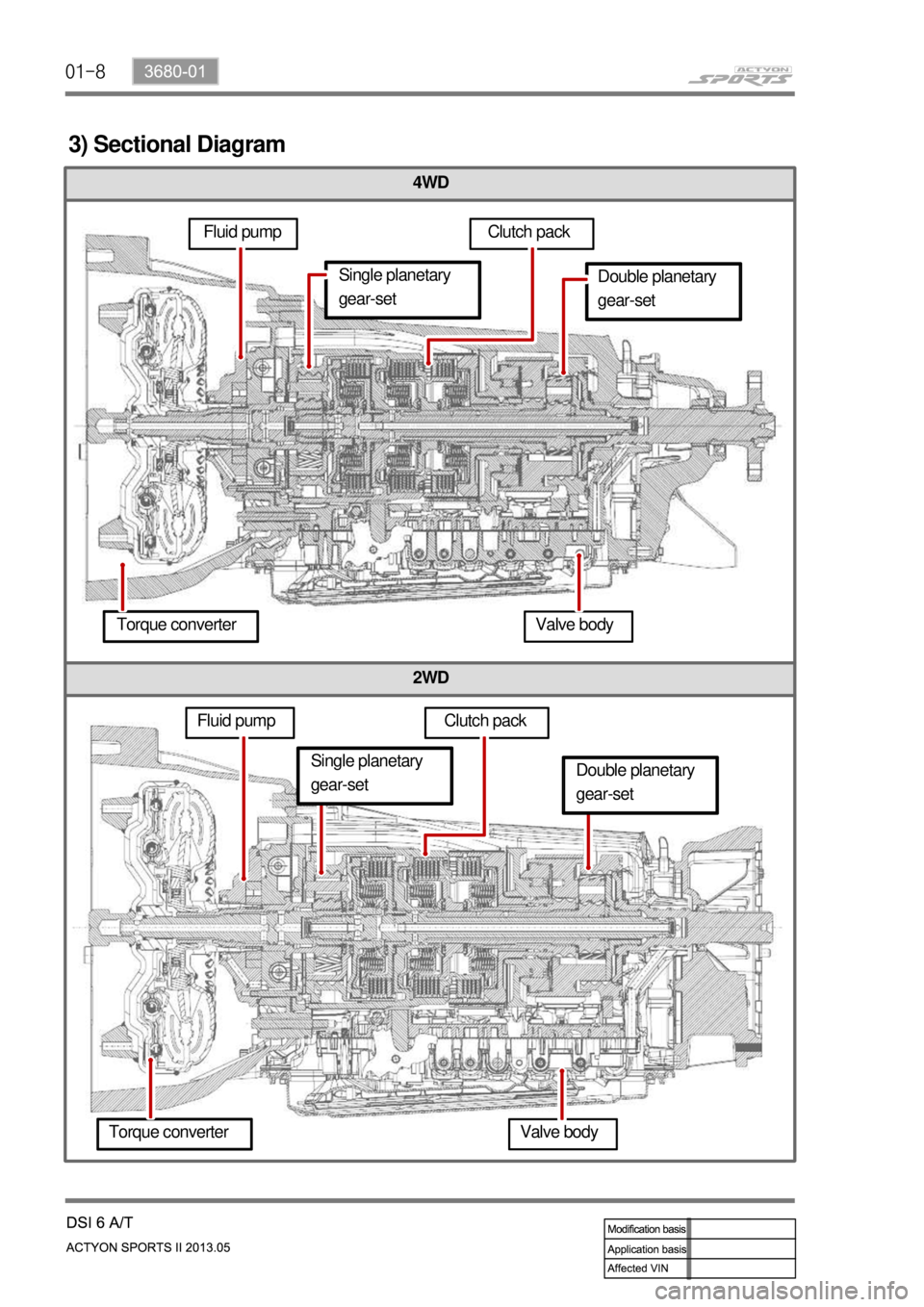
3) Sectional Diagram
Fluid pumpClutch pack
Double planetary
gear-set
Torque converter Valve body
Fluid pumpSingle planetary
gear-set
Clutch pack
Torque converter Valve body
Single planetary
gear-setDouble planetary
gear-set
Page 456 of 751
01-10
4. SHIFT PATTERN DIAGRAM
Page 470 of 751
01-24
Hydraulic Circuit Diagram ▶
Page 471 of 751
01-253680-01
1) Power Flow - Manual (M Position)
Functioning elements ▶
Control ▶C2 applied, FSG (Forward Sun Gear)
driven
B2 applied to hold Rear Planet Carrier
stationary
Provides engine breake effect -
-
-
S1 ON, C1 shift valve moved to the left end, C1 clutch not engaged
S1 ON, B2 shift valve moved to the left end, B2 band operated (S7 should be ON)
C2 shift valve open (S2 OFF), C2 clutch engaged by drive oil
Drive oil (for C2 clutch engagement) is regulated by VBS S6 -
-
-
-
Connecting Components ▶
Gear
ratioON / OFF solenoids Variable pressure sol. valve-VBS
S1 S2 S3 S4 S5(A) S6(A) S7(A) S8(A) S9(A) S10(A)
3.53 ON 1 0 1 0-1
Gear
ratioEngaged element
C1 C2 C3 B1 B2 OWC Lock-up
clutch
AO AI R AO AI
3.53 ON ON ON
Power Flow Diagram ▶
Manual 1st gear is not engaged even when
moving the manual valve to a certain position.
This gear state is obtained electronically by
solenoids S1 and S7.
Page 473 of 751
01-273680-01
2) Power Flow - 1st Gear (D)
Functioning elements ▶
Control ▶C2 applied, FSG (Forward Sun Gear) driven
1-2 OWC (One-Way Clutch) operated to hold Rear Planet Carrier stationary -
-
S1 ON, S2 OFF
S1 ON, C1 shift valve moved to the left end, C1 clutch not engaged
C2 shift valve open (S2 OFF), C2 clutch engaged by drive oil
Drive oil (for C2 clutch engagement) is regulated by VBS S6 -
-
-
-
Connecting Components ▶
Gear
ratioON / OFF solenoids Variable pressure sol. valve-VBS
S1 S2 S3 S4 S5(A) S6(A) S7(A) S8(A) S9(A) S10(A)
3.53 ON 1 0 0-1
Gear
ratioEngaged element
C1 C2 C3 B1 B2 OWC Lock-up
clutch
AO AI R AO AI
3.53 ON ON
Power Flow Diagram ▶
Page 475 of 751
01-293680-01
3) Power Flow - 2nd Gear (D)
Functioning elements ▶
Control ▶C2 applied, FSG (Forward Sun Gear) driven
B1 applied to hold Rear Planet Carrier stationary -
-
S1 ON, S4 ON, S2 OFF
S1 ON, C1 shift valve moved to the left end, C1 clutch not engaged
C2 shift valve open (S2 OFF), C2 clutch engaged by drive oil
Drive oil (for C2 clutch engagement) is regulated by VBS S6
S4 ON, B1 shift valve moved to the left end, B1 band operated
Drive oil (for B1 band engagement) is regulated by VBS S6 -
-
-
-
-
-
Connecting Components ▶
Gear
ratioON / OFF solenoids Variable pressure sol. valve-VBS
S1 S2 S3 S4 S5(A) S6(A) S7(A) S8(A) S9(A) S10(A)
2.14 ON ON 1 0
10-1
Gear
ratioEngaged element
C1 C2 C3 B1 B2 OWC Lock-up
clutch
AO AI R AO AI
2.14 ON ON
Power Flow Diagram ▶
Page 477 of 751
01-313680-01
4) Power Flow - 2nd Gear (D) Lock-Up
Connecting Components ▶
Gear
ratioON / OFF solenoids Variable pressure sol. valve-VBS
S1 S2 S3 S4 S5(A) S6(A) S7(A) S8(A) S9(A) S10(A)
2.14 ON ON ON 1 0 0 1 0-1 1
Gear
ratioEngaged element
C1 C2 C3 B1 B2 OWC Lock-up
clutch
AO AI R AO AI
2.14 ON ON
Power Flow Diagram ▶
Page 479 of 751
01-333680-01
5) Power Flow - 3rd Gear (D)
Functioning elements ▶
Control ▶C2 applied, FSG (Forward Sun Gear)
driven
C3 applied, Rear Planet Carrier driven
Rear Planet Gear Set is locked and its
output has the same gear ratio with Front
Gear Set. -
-
-
S1 ON, C1 shift valve moved to the left end, C1 clutch not engaged
C2 shift valve open (S2 OFF), C2 clutch engaged by drive oil
S3 and S7 ON, C3 shift valve moved to the left end, C3 clutch engaged -
-
-
Connecting Components ▶
Gear
ratioON / OFF solenoids Variable pressure sol. valve-VBS
S1 S2 S3 S4 S5(A) S6(A) S7(A) S8(A) S9(A) S10(A)
1.48 ON ON 1 0 1 0-1
Gear
ratioEngaged element
C1 C2 C3 B1 B2 OWC Lock-up
clutch
AO AI R AO AI
1.48 ON ON
Power Flow Diagram ▶
C3 clutch cannot be engaged if S7 is OFF
and the oil pressure is not supplied to C3
regulator valve.
Page 481 of 751
01-353680-01
6) Power Flow - 4th Gear (D) & 4th Gear (D) in Limp Home Mode
Functioning elements ▶
Control ▶C2 applied, FSG (Forward Sun Gear)
driven
C1 applied, Rear Planet Carrier driven -
-
S1 and S2 ON
C1 shift valve open (S1 OFF), C1 clutch engaged by drive oil
C2 shift valve open (S2 OFF), C2 clutch engaged by drive oil
Drive oil (for C1 and C2 engagement) is regulated by VBS S6 and S6 -
-
-
-
Connecting Components ▶
Gear
ratioON / OFF solenoids Variable pressure sol. valve-VBS
S1 S2 S3 S4 S5(A) S6(A) S7(A) S8(A) S9(A) S10(A)
1.16 0 0 0-1
Gear
ratioEngaged element
C1 C2 C3 B1 B2 OWC Lock-up
clutch
AO AI R AO AI
1.16 ON ON
Power Flow Diagram ▶
4th gear is used as Limp Home Mode.


