engine oil SSANGYONG NEW ACTYON SPORTS 2013 Owner's Guide
[x] Cancel search | Manufacturer: SSANGYONG, Model Year: 2013, Model line: NEW ACTYON SPORTS, Model: SSANGYONG NEW ACTYON SPORTS 2013Pages: 751, PDF Size: 72.63 MB
Page 211 of 751
15-110000-00
2) ECU Control
(1) Function
a. ECU Function
ECU receives and analyzes signals from various sensors and then modifies those signals into
permissible voltage levels and analyzes to control respective actuators.
ECU microprocessor calculates injection period and injection timing proper for engine piston speed and
crankshaft angle based on input data and stored specific map to control the engine power and emission
gas.
Output signal of the ECU microprocessor drives pressure control valve to control the rail pressure and
activates injector solenoid valve to control the fuel injection period and injection timing; so controls
various actuators in response to engine changes. Auxiliary function of ECU has adopted to reduce
emission gas, improve fuel economy and enhance safety, comforts and conveniences. For example,
there are EGR, booster pressure control, autocruise (export only) and immobilizer and adopted CAN
communication to exchange data among electrical systems (automatic T/M and brake system) in the
vehicle fluently. And Scanner can be used to diagnose vehicle status and defectives.
<00760097008c00990088009b00900095008e0047009b008c00940097008c00990088009b009c0099008c0047009900880095008e008c00470096008d0047006c006a007c00470090009a0047009500960099009400880093009300a000470054005b005700
47009b009600470052005f005c00b6006a004700880095008b> protected from factors like oil,
water and electromagnetism and there should be no mechanical shocks.
To control the fuel volume precisely under repeated injections, high current should be applied instantly
so there is injector drive circuit in the ECU to generate necessary current during injector drive stages.
Current control circuit divides current applying time (injection time) into full-in-current-phase and hold-
current-phase and then the injectors should work very correctly under every working condition.
b. Control Function
Controls by operating stages
To make optimum combustion under every operating stage, ECU should calculate proper injection
volume in each stage by considering various factors.
Starting injection volume control
During initial starting, injecting fuel volume will be calculated by function of temperature and engine
cranking speed. Starting injection continues from when the ignition switch is turned to ignition
position to till the engine reaches to allowable minimum speed.
Driving mode control
If the vehicle runs normally, fuel injection volume will be calculated by accelerator pedal travel and
engine rpm and the drive map will be used to match the drivers inputs with optimum engine power. -
-
-
Page 239 of 751
15-390000-00
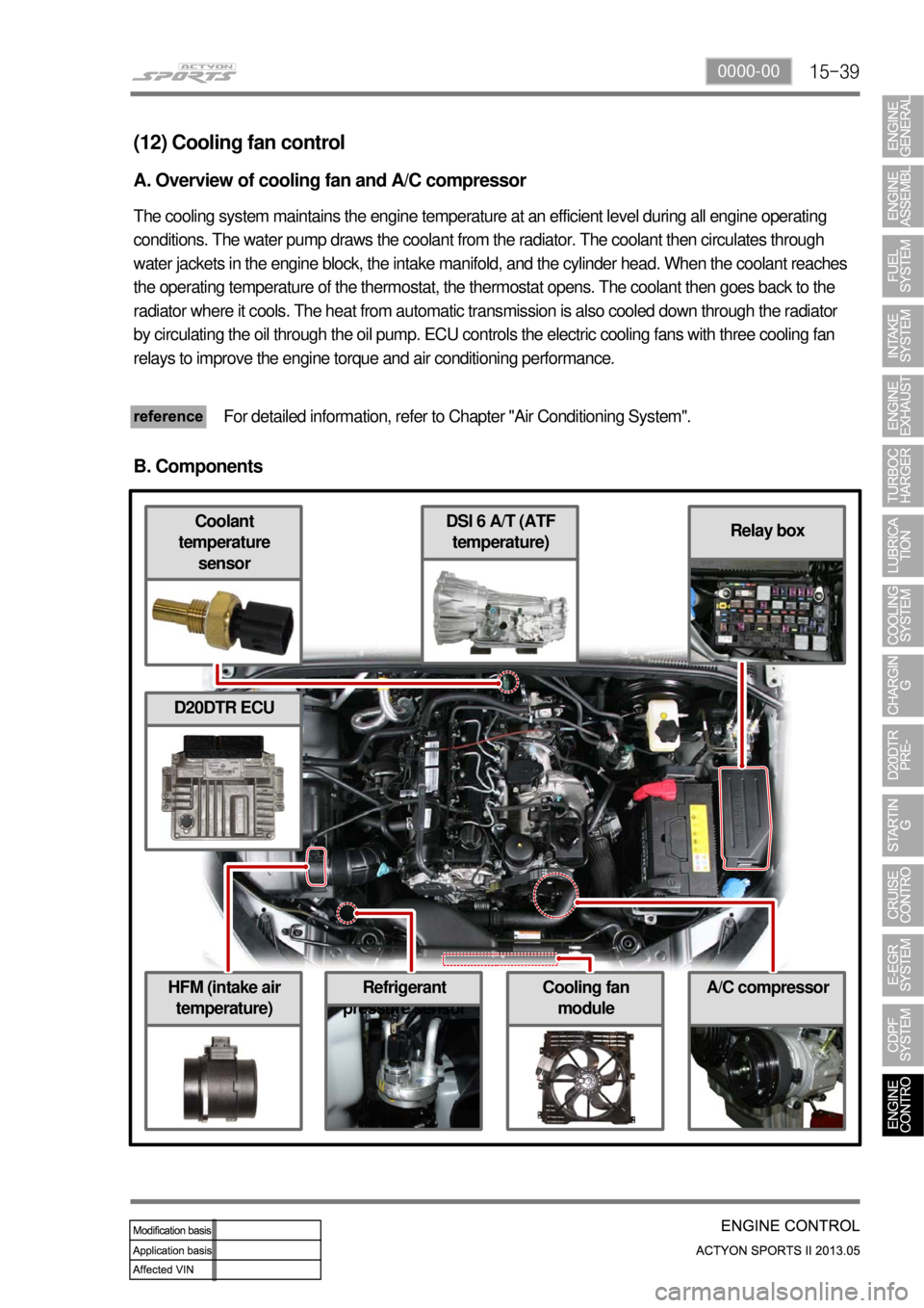
HFM (intake air
temperature)Cooling fan
module
DSI 6 A/T (ATF
temperature)Coolant
temperature
sensor
Refrigerant
pressure sensor
Relay box
(12) Cooling fan control
A. Overview of cooling fan and A/C compressor
The cooling system maintains the engine temperature at an efficient level during all engine operating
conditions. The water pump draws the coolant from the radiator. The coolant then circulates through
water jackets in the engine block, the intake manifold, and the cylinder head. When the coolant reaches
the operating temperature of the thermostat, the thermostat opens. The coolant then goes back to the
radiator where it cools. The heat from automatic transmission is also cooled down through the radiator
by circulating the oil through the oil pump. ECU controls the electric cooling fans with three cooling fan
relays to improve the engine torque and air conditioning performance.
For detailed information, refer to Chapter "Air Conditioning System".
B. Components
A/C compressor
D20DTR ECU
Page 250 of 751
15-50
E. Cautions
Use only specified Engine Oil (approved by MB Sheet 229.51) for CDPF. -
Use only specified engine oil (Low Ash Oil) ▶
The vehicle equipped with CDPF should use specific engine oil to improve the engine performance
and fuel economy, and ensure the service life of CDPF. -
Issue with normal engine oil ▶
Sulfur, one of the contents of engine oil is burned and generates soot that is not regenerated by the
DPF. This remains on the filter as ashes and keeps accumulating. Eventually, this ashes will block
the filter. -
Benefit for specified engine oil ▶
Minimized the sulfur content of engine oil which reduces the service life.
Improved fuel economy and emission level of CO2 with high performance and low viscosity.
Increased service life of engine oil with high resistance to temperature. -
-
-
Problems when using unspecified engine oil ▶
The service life of filter may be reduced by 30% or more by the ashes accumulated on the filter.
The fuel economy may be reduced because of engine rolling resistance, frequent regeneration of
DPF. -
-
These problems are also caused by oil with high sulfur content, such as tax exemption oil and
heating oil, etc. *
Page 252 of 751
01-31113-01
1. DESCRIPTION AND OPERATION
1) Cleanliness and Care
An automobile engine is a combination of many machined, honed, polished and lapped surfaces with
tolerances that are measured in the ten-thousanths of an inch.
When any internal engine parts are serviced, care and cleanliness are important.
A liberal coating of enigne oil should be applied to friction areas during assembly, to protect and lubricate
the surfaces on initial operation. Proper cleaning and protection of machined surfaces and friction areas
is part of the repair procedure.
This is considered standard shop practice even if not specifically stated.
Whenever valve train components are removed for service, they should be kept in order. They should be
installed in the same locations, and with the same mating surfaces, as when they were removed.
Battery cables should be disconnected before any major work is performed on the engine. Failure to
disconnect cables may result in damage to wire harness or other electrical parts.
Page 257 of 751
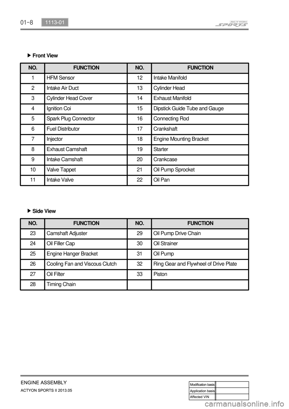
01-8
Front View ▶
NO. FUNCTION NO. FUNCTION
1 HFM Sensor 12 Intake Manifold
2 Intake Air Duct 13 Cylinder Head
3 Cylinder Head Cover 14 Exhaust Manifold
4 Ignition Coi 15 Dipstick Guide Tube and Gauge
5 Spark Plug Connector 16 Connecting Rod
6 Fuel Distributor 17 Crankshaft
7 Injector 18 Engine Mounting Bracket
8 Exhaust Camshaft 19 Starter
9 Intake Camshaft 20 Crankcase
10 Valve Tappet 21 Oil Pump Sprocket
11 Intake Valve 22 Oil Pan
NO. FUNCTION NO. FUNCTION
23 Camshaft Adjuster 29 Oil Pump Drive Chain
24 Oil Filler Cap 30 Oil Strainer
25 Engine Hanger Bracket 31 Oil Pump
26 Cooling Fan and Viscous Clutch 32 Ring Gear and Flywheel of Drive Plate
27 Oil Filter 33 Piston
28 Timing Chain
Side View ▶
Page 258 of 751
01-91113-01
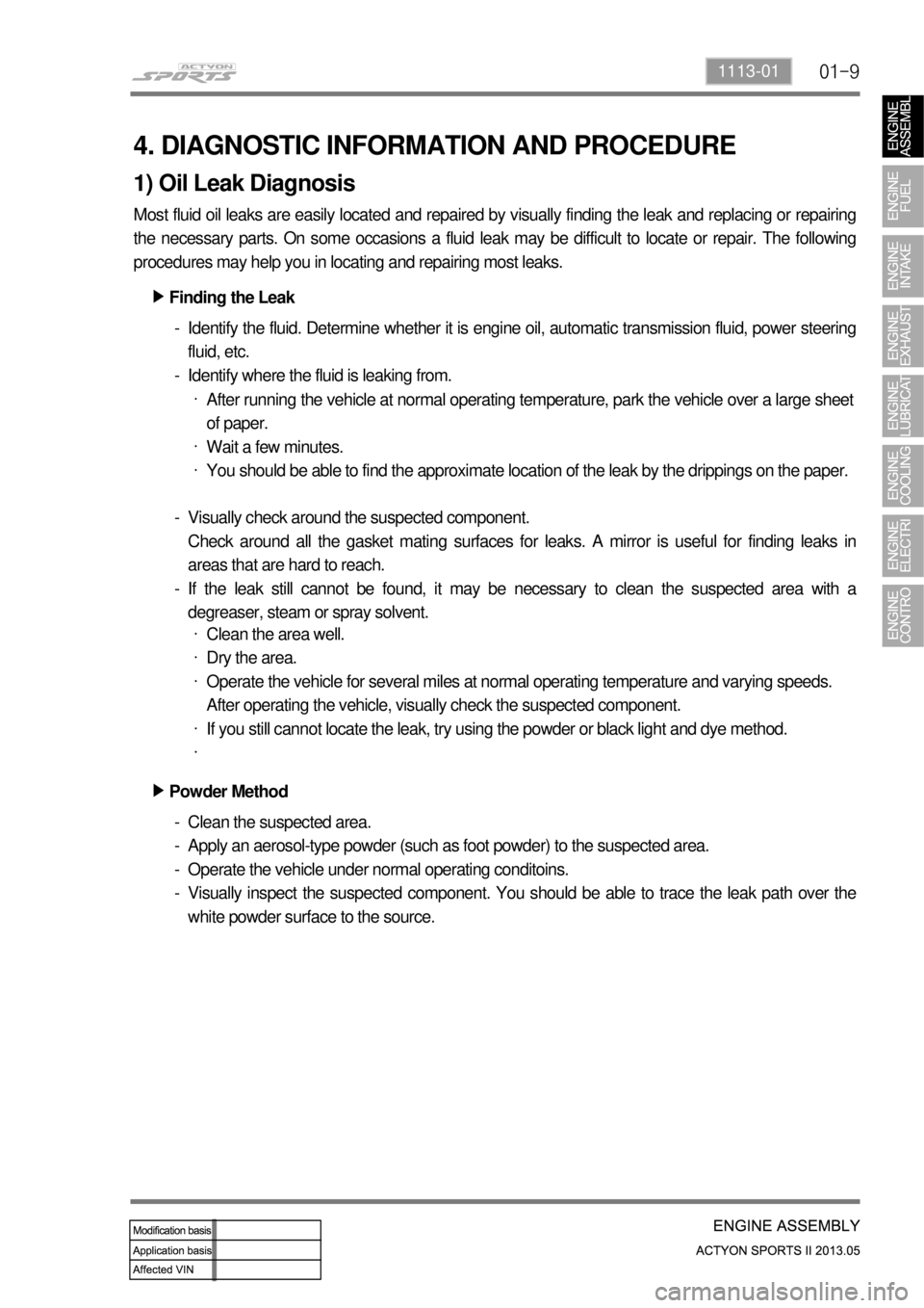
4. DIAGNOSTIC INFORMATION AND PROCEDURE
1) Oil Leak Diagnosis
Most fluid oil leaks are easily located and repaired by visually finding the leak and replacing or repairing
the necessary parts. On some occasions a fluid leak may be difficult to locate or repair. The following
procedures may help you in locating and repairing most leaks.
Finding the Leak ▶
Identify the fluid. Determine whether it is engine oil, automatic transmission fluid, power steering
fluid, etc.
Identify where the fluid is leaking from. -
-
After running the vehicle at normal operating temperature, park the vehicle over a large sheet
of paper.
Wait a few minutes.
You should be able to find the approximate location of the leak by the drippings on the paper. ·
·
·
Visually check around the suspected component.
Check around all the gasket mating surfaces for leaks. A mirror is useful for finding leaks in
areas that are hard to reach.
If the leak still cannot be found, it may be necessary to clean the suspected area with a
degreaser, steam or spray solvent. -
-
Clean the area well.
Dry the area.
Operate the vehicle for several miles at normal operating temperature and varying speeds.
After operating the vehicle, visually check the suspected component.
If you still cannot locate the leak, try using the powder or black light and dye method. ·
·
·
·
·
Clean the suspected area.
Apply an aerosol-type powder (such as foot powder) to the suspected area.
Operate the vehicle under normal operating conditoins.
Visually inspect the suspected component. You should be able to trace the leak path over the
white powder surface to the source. -
-
-
- Powder Method ▶
Page 259 of 751
01-10
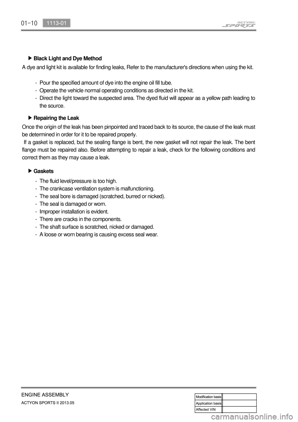
Black Light and Dye Method ▶
A dye and light kit is available for finding leaks, Refer to the manufacturer's directions when using the kit.
Pour the specified amount of dye into the engine oil fill tube.
Operate the vehicle normal operating conditions as directed in the kit.
Direct the light toward the suspected area. The dyed fluid will appear as a yellow path leading to
the source. -
-
-
Once the origin of the leak has been pinpointed and traced back to its source, the cause of the leak must
be determined in order for it to be repaired properly.
If a gasket is replaced, but the sealing flange is bent, the new gasket will not repair the leak. The bent
flange must be repaired also. Before attempting to repair a leak, check for the following conditions and
correct them as they may cause a leak.Repairing the Leak ▶
Gaskets ▶
The fluid level/pressure is too high.
The crankcase ventilation system is malfunctioning.
The seal bore is damaged (scratched, burred or nicked).
The seal is damaged or worn.
Improper installation is evident.
There are cracks in the components.
The shaft surface is scratched, nicked or damaged.
A loose or worn bearing is causing excess seal wear. -
-
-
-
-
-
-
-
Page 262 of 751
01-131113-01
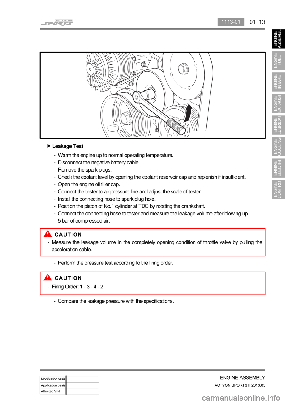
Leakage Test ▶
Warm the engine up to normal operating temperature.
Disconnect the negative battery cable.
Remove the spark plugs.
Check the coolant level by opening the coolant reservoir cap and replenish if insufficient.
Open the engine oil filler cap.
Connect the tester to air pressure line and adjust the scale of tester.
Install the connecting hose to spark plug hole.
Position the piston of No.1 cylinder at TDC by rotating the crankshaft.
Connect the connecting hose to tester and measure the leakage volume after blowing up
5 bar of compressed air. -
-
-
-
-
-
-
-
-
Measure the leakage volume in the completely opening condition of throttle valve by pulling the
acceleration cable. -
Perform the pressure test according to the firing order. -
Firing Order: 1 - 3 - 4 - 2 -
Compare the leakage pressure with the specifications. -
Page 298 of 751

07-91452-01
6) Alternator
Alternators are equipped with internal regulators.
Unlike three-wire generators, the alternator may be used with only two connections: battery positive and
an "D+" terminal to the charge indicator lamp.
As with other charging systems, the charge indicator lamp lights when the ignition switch is turned to
RUN, and goes out when the engine is running.
If the charge idicator is on with the engine running, a charging system defect is indicated. This indicato
r
light will glow at full brilliance for several kinds of defects as well as when the system voltage is too high
or too low.
The regulator voltage setting varies with temperature and limits the system voltage by controlling roto
r
field current.
Achieve correct average field current for proper system voltage control by varying the on-off time. At high
speeds, the on-time may be 10 percent and the off-time 90 percent.
At low speeds, with high electrical loads, the on-time may be 90 percent and the off-time 10 percent.
7) Charging System
Generators use a new type of regulator that incorporates a diode trio.
A Delta stator, a rectifier bridge, and a rotor with slip rings and brushes are electrically similar
to earlier generators.
A conventional pulley and fan are used.
There is no test hole.
8) Starter
Wound field starter motors have pole pieces, arranged around the armature, which are energized by
wound field coils.
Enclosed shift lever cranking motors have the shift lever mechanism and the solenoid plunger enclosed
in the drive housing, protecting them from exposure to dirt, icy conditions, and splashes.
In the basic circuit, solenoid windings are energized when the switch is closed.
The resulting plunger and shift lever movement causes the pinion to engage the engine flywheel ring
gear.
The solenoid main contacts close. Cranking then takes place.
When the engine starts, pinion overrun protects the armature from excessive speed until the switch is
opened, at which time the return spring causes the pinion to disengage.
To prevent excessive overrun, the switch should be released immediately after the engine starts.
Page 388 of 751
04-58210-01
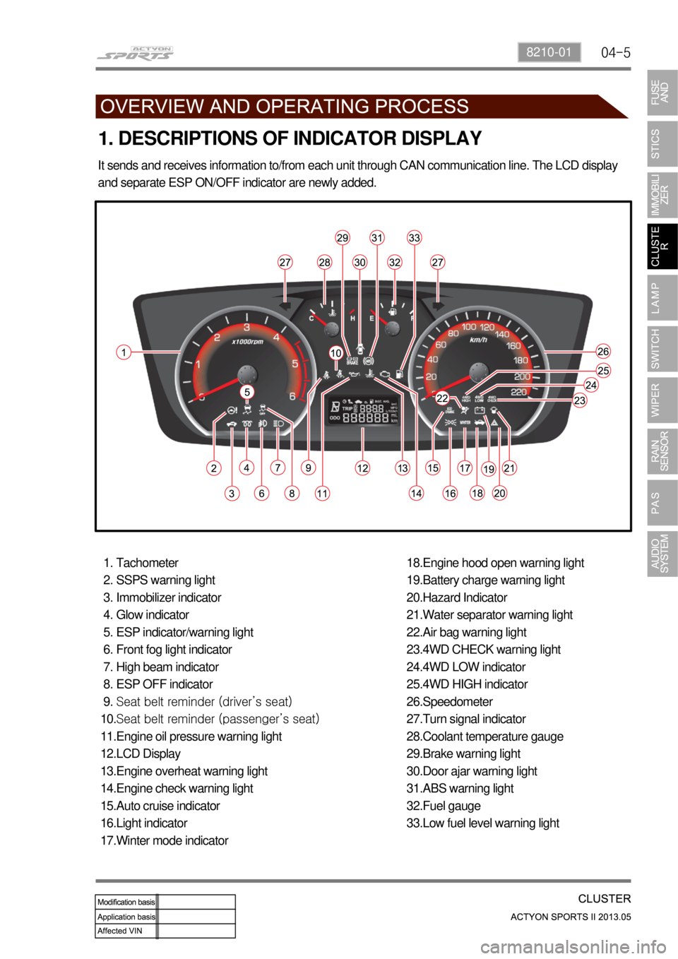
1. DESCRIPTIONS OF INDICATOR DISPLAY
Tachometer
SSPS warning light
Immobilizer indicator
Glow indicator
ESP indicator/warning light
Front fog light indicator
High beam indicator
ESP OFF indicator
Seat belt reminder (driver’s seat)
Seat belt reminder (passenger’s seat)
Engine oil pressure warning light
LCD Display
Engine overheat warning light
Engine check warning light
Auto cruise indicator
Light indicator
Winter mode indicator 1.
2.
3.
4.
5.
6.
7.
8.
9.
10.
11.
12.
13.
14.
15.
16.
17.Engine hood open warning light
Battery charge warning light
Hazard Indicator
Water separator warning light
Air bag warning light
4WD CHECK warning light
4WD LOW indicator
4WD HIGH indicator
Speedometer
Turn signal indicator
Coolant temperature gauge
Brake warning light
Door ajar warning light
ABS warning light
Fuel gauge
Low fuel level warning light 18.
19.
20.
21.
22.
23.
24.
25.
26.
27.
28.
29.
30.
31.
32.
33. It sends and receives information to/from each unit through CAN communication line. The LCD display
and separate ESP ON/OFF indicator are newly added.