ECO mode SSANGYONG NEW ACTYON SPORTS 2013 Service Manual
[x] Cancel search | Manufacturer: SSANGYONG, Model Year: 2013, Model line: NEW ACTYON SPORTS, Model: SSANGYONG NEW ACTYON SPORTS 2013Pages: 751, PDF Size: 72.63 MB
Page 189 of 751
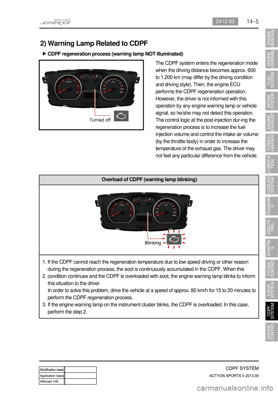
14-52412-02
The CDPF system enters the regeneration mode
when the driving distance becomes approx. 600
to 1,200 km (may differ by the driving condition
and driving style). Then, the engine ECU
performs the CDPF regeneration operation.
However, the driver is not informed with this
operation by any engine warning lamp or vehicle
signal, so he/she may not detect this operation.
The control logic at the post-injection dur-ing the
regeneration process is to increase the fuel
injection volume and control the intake air volume
(by the throttle body) in order to increase the
temperature of the exhaust gas. The driver may
not feel any particular difference from the vehicle.
Overload of CDPF (warning lamp blinking)
2) Warning Lamp Related to CDPF
CDPF regeneration process (warning lamp NOT illuminated) ▶
If the CDPF cannot reach the regeneration temperature due to low speed driving or other reason
during the regeneration process, the soot is continuously accumulated in the CDPF. When this
condition continues and the CDPF is overloaded with soot, the engine warning lamp blinks to inform
this situation to the driver.
In order to solve this problem, drive the vehicle at a speed of approx. 80 km/h for 15 to 20 minutes to
perform the CDPF regeneration process.
If the engine warning lamp on the instrument cluster blinks, the CDPF is overloaded. In this case,
perform the step 2. 1.
2.
3.
Page 211 of 751
15-110000-00
2) ECU Control
(1) Function
a. ECU Function
ECU receives and analyzes signals from various sensors and then modifies those signals into
permissible voltage levels and analyzes to control respective actuators.
ECU microprocessor calculates injection period and injection timing proper for engine piston speed and
crankshaft angle based on input data and stored specific map to control the engine power and emission
gas.
Output signal of the ECU microprocessor drives pressure control valve to control the rail pressure and
activates injector solenoid valve to control the fuel injection period and injection timing; so controls
various actuators in response to engine changes. Auxiliary function of ECU has adopted to reduce
emission gas, improve fuel economy and enhance safety, comforts and conveniences. For example,
there are EGR, booster pressure control, autocruise (export only) and immobilizer and adopted CAN
communication to exchange data among electrical systems (automatic T/M and brake system) in the
vehicle fluently. And Scanner can be used to diagnose vehicle status and defectives.
<00760097008c00990088009b00900095008e0047009b008c00940097008c00990088009b009c0099008c0047009900880095008e008c00470096008d0047006c006a007c00470090009a0047009500960099009400880093009300a000470054005b005700
47009b009600470052005f005c00b6006a004700880095008b> protected from factors like oil,
water and electromagnetism and there should be no mechanical shocks.
To control the fuel volume precisely under repeated injections, high current should be applied instantly
so there is injector drive circuit in the ECU to generate necessary current during injector drive stages.
Current control circuit divides current applying time (injection time) into full-in-current-phase and hold-
current-phase and then the injectors should work very correctly under every working condition.
b. Control Function
Controls by operating stages
To make optimum combustion under every operating stage, ECU should calculate proper injection
volume in each stage by considering various factors.
Starting injection volume control
During initial starting, injecting fuel volume will be calculated by function of temperature and engine
cranking speed. Starting injection continues from when the ignition switch is turned to ignition
position to till the engine reaches to allowable minimum speed.
Driving mode control
If the vehicle runs normally, fuel injection volume will be calculated by accelerator pedal travel and
engine rpm and the drive map will be used to match the drivers inputs with optimum engine power. -
-
-
Page 224 of 751
15-24
This is done periodically under certain operating conditions. When the resetting is finished, the new
minimum pulse value replaces the value obtained during the previous resetting. The first MDP value is
provided by the C3I. Each resetting then allows the closed loop of the MDP to be updated according to
the deviation of the injector.
B. Detection of leaks in the cylinders
The accelerometer is also used to detect any injector which may have stuck open. The detection
principle is based on monitoring the ratio. If there is a leak in the cylinder, the accumulated fuel self-
ignites as soon as the temperature and pressure conditions are favorable (high engine speed, high load
and small leak).
This combustion is set off at about 20 degrees before TDC and before main injection.
The ratio therefore increases considerably in the detection window. It is this increase which allows the
leaks to be detected. The threshold beyond which a fault is signaled is a percentage of the maximum
possible value of the ratio.
Because of the severity of the recovery process (engine shut-down), the etection must be extremely
robust.
An increase in the ratio can be the consequence of various causes:
Pilot injection too much
Main combustion offset
Fuel leak in the cylinder -
-
-
If the ratio becomes too high, the strategy initially restricts the pilot injection flow and retards the main
injection. If the ratio remains high despite these interventions, this shows that a real leak is present, a
fault is signaled and the engine is shut down.
C. Detection of an accelerometer fault
This strategy permits the detection of a fault in the sensor or in the wiring loom connecting the sensor to
the ECU.
It is based on detection of the combustion. When the engine is idling, the detection window is set too low
for the combustion caused by the main injection. If the ratio increases, this shows that the knock sensor
is working properly, but otherwise a fault is signaled to indicate a sensor failure. The recovery modes
associated with this fault consist of inhibition of the pilot injection and discharge through the injectors.
Page 275 of 751
02-6
1) Starting Mode
When the ignition is turned ON, the ECM turns the fuel pump relay on for 1 second. The fuel pump then
builds fuel pressure. The ECM also checks the Engine Coolant Temperature (ECT) sensor and the
Throttle Position (TP) sensor and determines the proper air/fuel ratio for starting the engine. This ranges
from1.5 to 1 at -36 °C (-33 °F) coolant temperature to 14.7 to 1 at 94 °C (201 °F) coolant
temperature. The ECM controls the amountof fuel delivered in the starting mode by changing how long
the fuel injector is turned on and off. This is done by ''pulsing" the fuel injectors for very short times.
2) Run Mode
The run mode has two conditions called ''open loop" and ''closed loop".
3) Open Loop
When the engine is first started and it is above 690 rpm, the system goes into "open loop" operation. In
"open loop", the ECM ignores the signal from the HO2S and calculates the air/fuel ratio based on inputs
from the ECT sensor and the MAF sensor. The ECM stays in "open loop" until the following conditions
are met:
The O2 has a varying voltage output, showing that it is hot enough to operate properly.
The ECT sensor is above a specified temperature (22.5 °C).
A specific amount of time has elapsed after starting the engine. -
-
-
4) Closed Loop
The specific values for the above conditions vary with different engines and are stored in the
Electronically Erasable Programmable Read-Only Memory (EEPROM).
When these conditions are met, the system goes into "closed loop" operation. In "closed loop", the ECM
calculates the air/fuel ratio (fuel injector on- time) based on the signals from the O2 sensors. This allows
the air/fuel ratio to stay very close to 14.7 to 1.
5) Acceleration Mode
The ECM responds to rapid changes in throttle position and airflow and provides extra fuel.
6) Deceleration Mode
The ECM responds to changes in throttle position and airflow and reduces the amount of fuel. When
deceleration is very fast, the ECM can cut off fuel completely for short periods of time.
Page 297 of 751
07-8
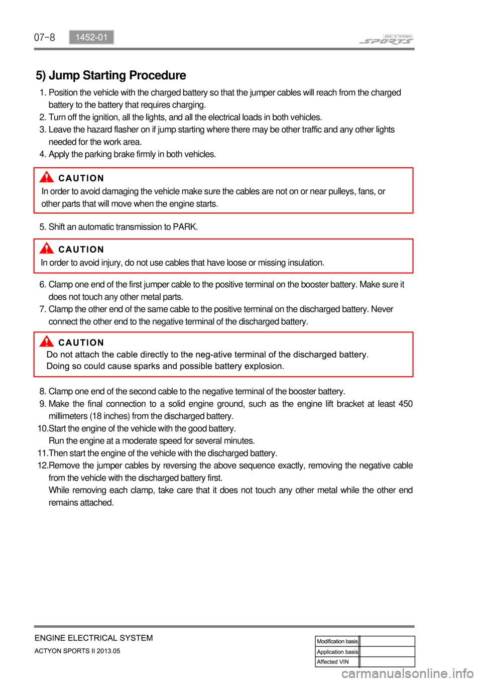
5) Jump Starting Procedure
Position the vehicle with the charged battery so that the jumper cables will reach from the charged
battery to the battery that requires charging.
Turn off the ignition, all the lights, and all the electrical loads in both vehicles.
Leave the hazard flasher on if jump starting where there may be other traffic and any other lights
needed for the work area.
Apply the parking brake firmly in both vehicles. 1.
2.
3.
4.
Shift an automatic transmission to PARK. 5.
Clamp one end of the first jumper cable to the positive terminal on the booster battery. Make sure it
does not touch any other metal parts.
Clamp the other end of the same cable to the positive terminal on the discharged battery. Never
connect the other end to the negative terminal of the discharged battery. 6.
7.
Clamp one end of the second cable to the negative terminal of the booster battery.
Make the final connection to a solid engine ground, such as the engine lift bracket at least 450
millimeters (18 inches) from the discharged battery.
Start the engine of the vehicle with the good battery.
Run the engine at a moderate speed for several minutes.
Then start the engine of the vehicle with the discharged battery.
Remove the jumper cables by reversing the above sequence exactly, removing the negative cable
from the vehicle with the discharged battery first.
While removing each clamp, take care that it does not touch any other metal while the other end
remains attached. 8.
9.
10.
11.
12.In order to avoid damaging the vehicle make sure the cables are not on or near pulleys, fans, or
other parts that will move when the engine starts.
In order to avoid injury, do not use cables that have loose or missing insulation.
Page 317 of 751
02-78710-01
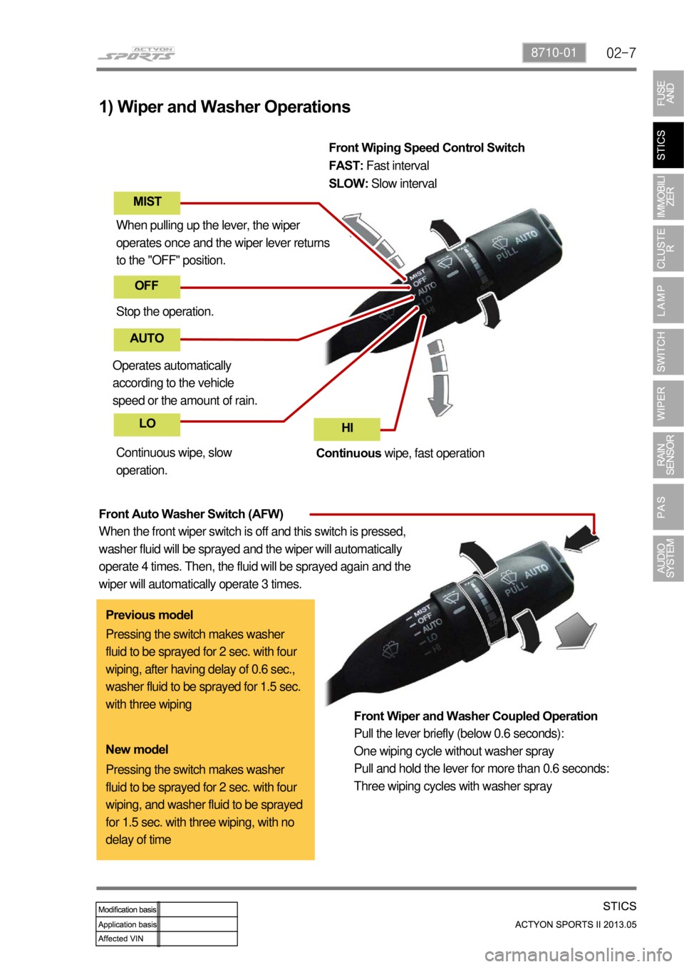
1) Wiper and Washer Operations
When pulling up the lever, the wiper
operates once and the wiper lever returns
to the "OFF" position.
Stop the operation.
Operates automatically
according to the vehicle
speed or the amount of rain. Continuous wipe, slow
operation. Front Wiping Speed Control Switch
FAST: Fast interval
SLOW: Slow interval
Continuous wipe, fast operation
Front Wiper and Washer Coupled Operation
Pull the lever briefly (below 0.6 seconds):
One wiping cycle without washer spray
Pull and hold the lever for more than 0.6 seconds:
Three wiping cycles with washer spray
Front Auto Washer Switch (AFW)
When the front wiper switch is off and this switch is pressed,
washer fluid will be sprayed and the wiper will automatically
operate 4 times. Then, the fluid will be sprayed again and the
wiper will automatically operate 3 times.
MIST OFF
AUTO
LO HI
Previous model
Pressing the switch makes washer
fluid to be sprayed for 2 sec. with four
wiping, after having delay of 0.6 sec.,
washer fluid to be sprayed for 1.5 sec.
with three wiping
Pressing the switch makes washer
fluid to be sprayed for 2 sec. with four
wiping, and washer fluid to be sprayed
for 1.5 sec. with three wiping, with no
delay of time New model
Page 331 of 751

02-218710-01
▶Volume Sensitive INT (Intermittent) Wiper
For RKSTICS without the rain sensor, perform the following operation:
Controls the wiper intermittent operation by the values from the vehicle\
speed and the volume
(resistance).
-
Calculates and converts the Intermittent interv al automatically by obtaining the INT VOLUME
when the ignition switch and the INT switch is in the "ON" position.
The wipers are operated in vehicle speed sensitiv e mode when turning the INT switch to the
"ON" position with the engine running or starting the engine with the INT switch positioned to
"ON".
Intermittent interval (at 0 km/h): 3 ± 0.5 ~ 19 ± 2 seconds
˙
˙
˙
Vehicle speed calculation
-
[Input the vehicle speed]
It is calculated by the numbers of input pulses for one second.
VOLUME calculation
-
The pause time of the vehicle speed sensitive INT wiper is calculated by\
the INT volume (inpu
t
voltage). Each level has the hysteresis.
˙
Pause time calculation
-
Pause time means the duration that wipers are stopped at parking positio\
n.
Elapsed time means the duration after the wiper motor started to operate from parking
position.
The pause time is calculated by the vehicle speed and the VOLUME.
※If the pause time is below 1.0 second, the wipers operate without pause.
※If the pause time is over 1.5 seconds, the wipers operate intermittently.
˙
˙
˙ 60 [km/h] × 60 [sec]
1 [PULSE/SEC] =
637 × 4 PULSE ≒ 1.41 [km/h]
Page 340 of 751
02-30
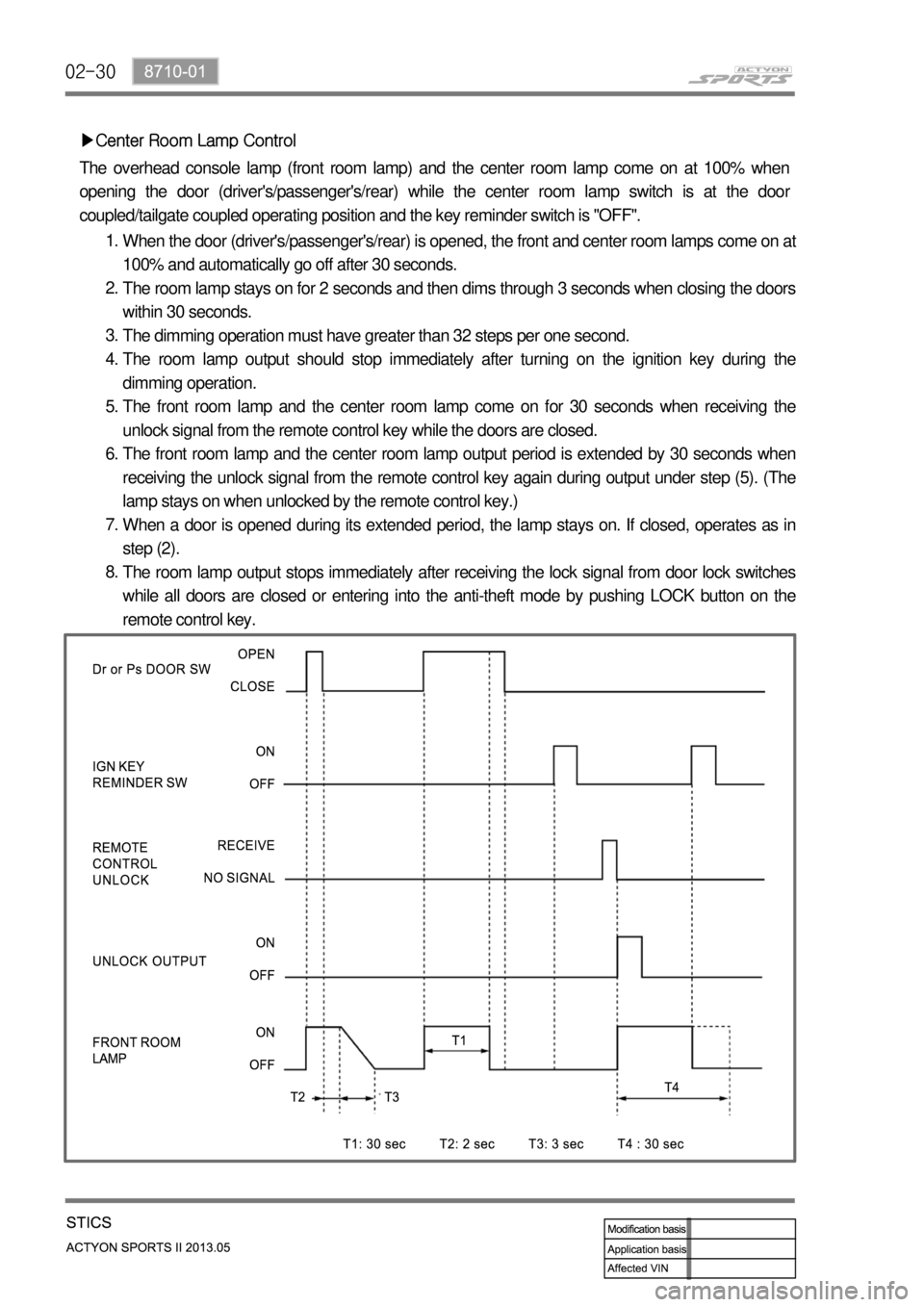
▶Center Room Lamp Control
The overhead console lamp (front room lamp) and the center room lamp come on at 100% when
opening the door (driver's/passenger's/rear) while the center room lamp switch\
is at the doo
r
coupled/tailgate coupled operating position and the key reminder switch \
is "OFF".
When the door (driver's/passenger's/rear) is opened, the front and center room lamps come on at
100% and automatically go off after 30 seconds.
The room lamp stays on for 2 seconds and then dims through 3 seconds whe\
n closing the doors
within 30 seconds.
The dimming operation must have greater than 32 steps per one second.
The room lamp output should stop immediately after turning on the ignition key during the
dimming operation.
The front room lamp and the center room lamp come on for 30 seconds when\
receiving the
unlock signal from the remote control key while the doors are closed.
The front room lamp and the center room lamp output period is extended b\
y 30 seconds when
receiving the unlock signal from the remote control key again during output under step (5). (The
lamp stays on when unlocked by the remote control key.)
When a door is opened during its extended period, the lamp stays on. If closed, operates as in
step (2).
The room lamp output stops immediately after receiving the lock signal from door lock switches
while all doors are closed or entering into the anti-theft mode by pushi\
ng LOCK button on the
remote control key.
1.
2.
3.
4.
5.
6.
7.
8.
Page 342 of 751
02-32
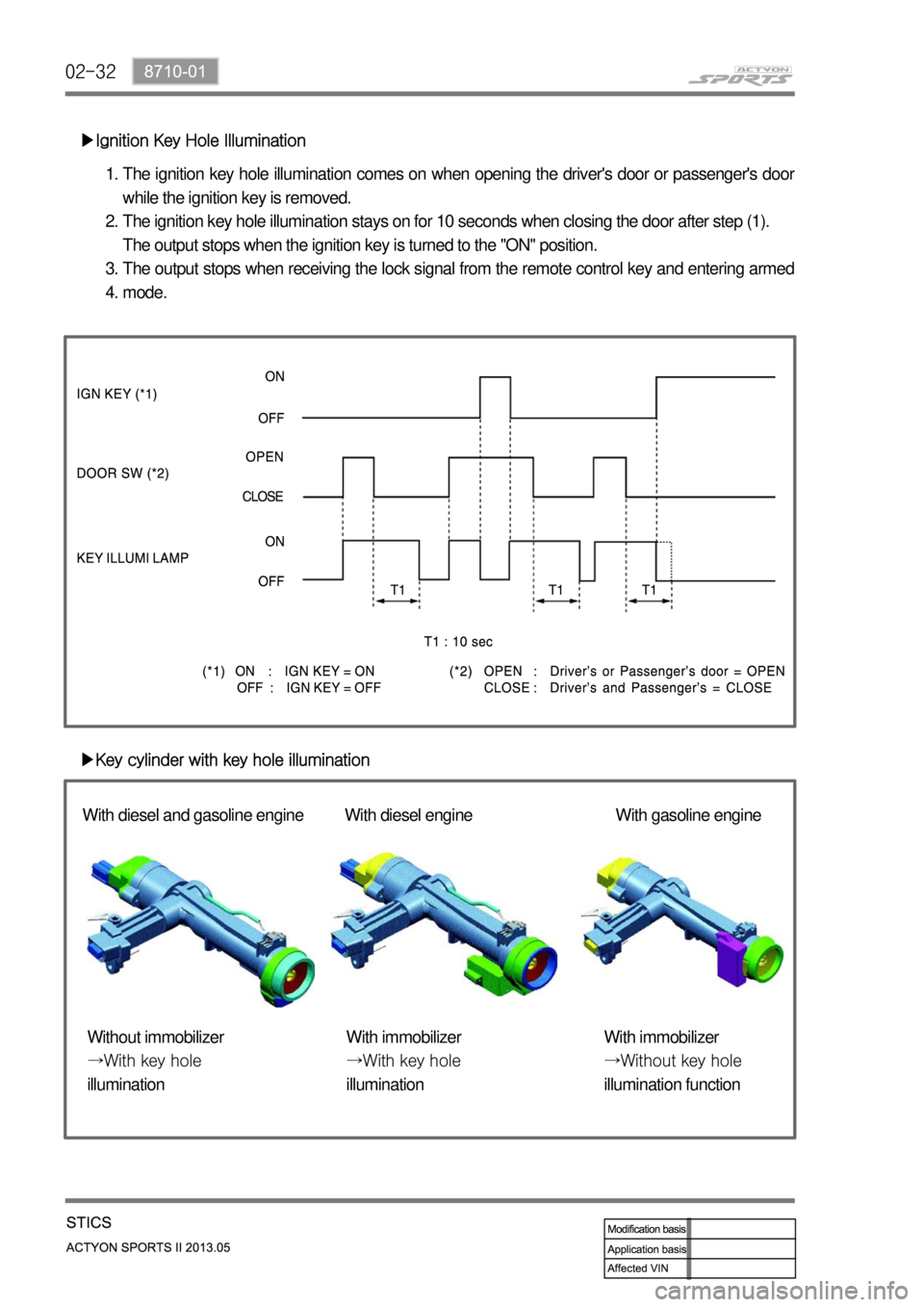
▶Ignition Key Hole IlluminationThe ignition key hole illumination comes on when opening the driver's door or passenger's doo
r
while the ignition key is removed.
The ignition key hole illumination stays on for 10 seconds when closing \
the door after step (1).
The output stops when the ignition key is turned to the "ON" position.
The output stops when receiving the lock signal from the remote control key and entering armed
mode.
1.
2.
3.
4.
▶Key cylinder with key hole illumination With diesel and gasoline engine With diesel engine With gasoline engine
Without immobilizer
→With key hole
illumination With immobilizer
→With key hole
illumination With immobilizer
→Without key hole
illumination function
Page 353 of 751

02-438710-01
▶Time Lag Power Window Control
The power window relay output is "ON" when turning on the ignition switc\
h.
The power window relay output is "ON" for 30 seconds when turning off th\
e ignition switch.
The power window relay output is "OFF" when opening the driver's door or the passenger's
door.
The power window relay is turned "OFF" when receiving the remote control\
key lock signal
(armed mode) during its extended operation period of 30 seconds.
1.
2.
3.