Turbo SSANGYONG NEW REXTON 2012 User Guide
[x] Cancel search | Manufacturer: SSANGYONG, Model Year: 2012, Model line: NEW REXTON, Model: SSANGYONG NEW REXTON 2012Pages: 600, PDF Size: 73.29 MB
Page 220 of 600

0000-00
1. COMPONENTS
1. E-EGR valve: Controlling the EGR valve electrically and sends the valve location signal to ECU
(vacuum modulator control has been deleted).
2. EGR cooler:
VGT turbochargerIntake manifold
Turbocharger intercooler
(intake air)
EGR gas (from EG
R
cooler)
E-EGR
valve
Exhaust manifoldE-EGR
valveCoolant
To intake
manifold
EGR cooler
EGR pipe
E-EGR valveDecreasing EGR gas (NOx) efficiently by cooling the EGR gas and let it flow to the
intake manifold. The components of the exhaust system consist of:
Throttle body
Exhaust manifold
Page 222 of 600

Under air cleaner in right side
of engine compartment
2. CDPF (EURO IV) SYSTEM
The CDPF system is only installed to the D27DT engine, and the major changes comparing to the
previous D27DT engine is as follows:
CDPF (Catalyst & Diesel Particulate Filter) and Sensors
Front exhaust gas
temperature sensor
CDPF Exhaust Gas Temperature Sensor
The two temperature sensors
in-side the CDPF are installed
inexhaust manifold (front
exhaustgas temperature
sensor) and inDOC (rear
exhaust gas tempera-ture
sensor), and perform the fol-
lowing functions.Front Exhaust Gas Tempera-ture
Sensor:
Measures the exhaust gas tem-
perature of the exhaust manifold. As it
is installed in front of the VGT
turbocharger, it also monitors the
exhaust gas tempera-ture coming to
the turbocharger. If the temperature of
the exhaust gas flowing to the
turbocharger is higher than the
specification, the engine lowers the
exhaust gas temperature.Rear Exhaust Gas Tempera-
ture Sensor:
Measures the increased ex-
haust gas temperature after
the oxidation process of DOC.
If the temperature is below
amount is increased to
increase the temperature.
As the soot is filtered in the CDPF, the pressure between the front side and the rear side of the filter is
different from each other. If the amount of soot is over 28 g, the soot is burnt in the CDPF. The
combustion is determined depending on the pressure difference, temperature of exhaust gas and
Page 223 of 600

1533-01
Throttle Body
CDPF system controls the amount of intake air by controlling the
electronic throttle body. The electronic throttle body has the
following main functions.
CDPF control - added a function that increases the exhaust gas
temperature by closing the throttle valve flap to minimize the intake
air amount by the fuel injection amount during the CDPF
regeneration range with the low engine load range.
ON/OFF control - prevents the engine from turning off with
vibration and noise by closing the throttle body flap to block the
intake air when the engine is stopped.
Duty control - controls the valve inside the throttle body to burn
more EGR gas in the EGR valve operating range.
VGT Turbocharger and Front Exhaust Gas Temperature Sensor
Turbocharger may become weaker if high tem-
perature exhaust gas passes through the tur-
bocharger for DPF regeneration process.
The front exhaust gas temperature sensor moni-tors
the temperature of the exhaust gas that flows into the
turbocharger.
If the temperature of the exhaust gas that passes
through the exhaust manifold is higher than the
specification, the ECU decreases the fuel injection
amount and increases the EGR gas intake amount to
decrease the exhaust gas temperature.Front exhaust gas
temperature sensor
Page 259 of 600

0000-00
Right view
Front exhaust gas temperature
sensor
Oil dipstick tube &
gauge assembly
E-VGT actuator
E-VGT turbocharger
Coolant screw plug
Oil drain plug
Left view
Thermostat assembly
Variable swirl valve assembly
E-EGR valve
E-EGR solenoid valve
EGR cooler
Electronic throttle body
Oil cooler assembly
Page 267 of 600

0000-00
Hot water inlet pipe2 -
1 -
1 -
4 25~2.5Nm -
4 -
2 -
6 -
6 -
1 -
2 -
2 -
1 10~14Nm -
1 -
M8 10
-
M8 3
-
1
-
M8 1
-
T/C oil supply pipe M6(to block) 1
-
M6
(to turbocharger)1
-
T/C oil return pipe
2 -
(to turbocharger)2
-
EGR valve
3 -
EGR pipe bolt (to exhaust
manifold)
2 -
EGR pipe bolt (to EGR
cooler)
2 -
Name SizeNumbers of
fastenerTightening
torque (Nm)Note (total
tightening
torque)
Hot water inlet pipe
2 -
Alternator
1 -
1 -
Air conditioner
compressor
4 25~2.5Nm -
Air conditioner bracket
4 -
Intake manifold
2 -
6 -
Oil filter module
6 -
1 -
2 -
Knock sensor
2 -
Camshaft position sensor
1 10~14Nm -
T-MAP pressure sensor
1 -
Exhaust manifold M8 10
-
Turbocharger M8 3
-
T/C support bolt M8 1
-
Page 272 of 600

0000-00
Component SizeBolt
QuantitySpecified torque
(Nm)Remark
(Total torque)
Hot water inlet pipe
2 -
Alternator
1 -
1 -
A/C bracket
4 7.8~11.8Nm -
A/C sub bracket
4 -
Intake manifold
2 -
6 -
Oil filter module
6 -
1 -
2 -
Knock sensor
2 -
Cam position sensor
1 10~14Nm -
Booster pressure sensor
2 -
Exhaust manifold M8 10
-
Turbocharger M8 3
-
Support bolt 1
-
Support nut M8 1
-
T/C oil supply pipe M6(block side) 1
-
M6(turbo side) 1
-
T/C oil return pipe
2 -
2 -
EGR valve
2 -
EGR pipe bolt
(Intake side)
2 -
EGR pipe bolt
(EGR cooler side)
2 -
EGR combination bolt
4 -
16 -
Idle pulley/Tensioner
pulley1
-
Page 342 of 600

2. INSPECTION
1) Troubleshooting
When Abnormal Noises are Heard from the Engine Room
For the vehicle equipped with DI engine, if a learning noise occurs in each range or other noises
occur, the major cause of it is a faulty turbocharger assembly. But an interference issue, poor
tightness or loose in the intake and exhaust system also can cause those noises. This is mainly
because the operator didn't follow the instruction exactly when reconnecting the intake hoses and
pipes which were disconnected to check the system or replace the air cleaner. If the intake system is
free of any faults, check the EGR and PCV oil separator connected to the intake system.
The figure may be different from the actual engine. Therefore, read thoroughly below before replacing
the parts.
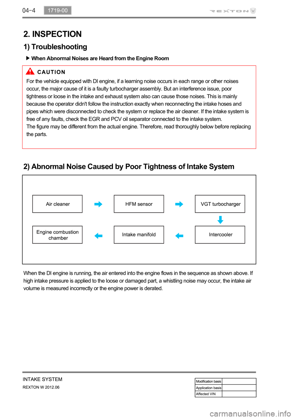
2) Abnormal Noise Caused by Poor Tightness of Intake System
When the DI engine is running, the air entered into the engine flows in the sequence as shown above. If
high intake pressure is applied to the loose or damaged part, a whistling noise may occur, the intake air
volume is measured incorrectly or the engine power is derated.
Page 354 of 600

1914-01
1. SPECIFICATION
Unit Description Specification
TurbochargerMax. expansion coefficient 4.0
Max. turbine speed 226,000rpm
Max. temperature of turbine housing
Weight 6.5kg
E-VGT actuator Operation duty cycle 250Hz
Page 355 of 600

2. INSPECTION
1) Cautions During Driving
The following lists cautions to take during test drive and on the turbocharger vehicle, which must be
considered during the operation.
It's important not to drastically increase the engine rpm starting the engine. It could make rotation at
excessive speed even before the journal bearing is lubricated and when the turbocharger rotates in
poor oil supply condition, it could cause damage of bearing seizure within few seconds.
If the engine is running radically after replacing the engine oil or oil filter brings poor oil supply
condition. To avoid this, it's necessary to start off after idling the engine for about 1 minute allowing oil
to circulate to the turbocharger after the replacement.
When the engine is stopped abruptly after driving at high speed, the turbocharger continues to rotate
in condition where the oil pressure is at '0'. In such condition, an oil film between the journal bearing
and the housing shaft journal section gets broken and this causes abrasion of the journal bearing due
to the rapid contact. The repeat of such condition significantly reduces life of the turbocharger.
Therefore, the engine should be stopped possibly in the idle condition. 1.
2.
3.
After string for long period of time during winter season or in the low temperature condition where the
fluidity of engine oil declines, the engine, before being started, should be cranked to circulate oil and
must drive after checking the oil pressure is in normal condition by idling the engine for few minutes.
Page 356 of 600

1914-01
2) Inspection of Turbocharger
When problem occurs with the turbocharger, it could cause engine power decline, excessive discharge of
exhaust gas, outbreak of abnormal noise and excessive consumption of oil.
On-board Inspection 1.
Check the bolts and nuts foe looseness or missing
Check the intake and exhaust manifold for looseness or damage
Check the oil supply pipe and drain pipe for damages
Check the housing for crack and deterioration -
-
-
-
Inspection of turbine 2.
Remove the exhaust pipe at the opening of the turbine and check, with a lamp, the existence of
interference of housing and wheel, oil leakage and contamination (at blade edge) of foreign materials.
Interference: In case where the oil leak sign exists, even the small traces of interferences on the
turbine wheel mean, most of times, that abrasion has occurred on the journal bearing. Must inspect
after overhauling the turbocharger.
Oil Leakage: Followings are the reasons for oil leakage condition -
-
Idling for long period of time can cause oil leakage to the turbine side due to low pressure of exhaust
gas and the rotation speed of turbine wheel. Please note this is not a turbocharger problem.
Oil Drain Pipe Defect
In case where oil flow from the turbocharger sensor housing to the crank case is not smooth would
become the reason for leakage as oil builds up within the center housing. Also, oil thickens (sludge) at
high temperature and becomes the indirect reason of wheel hub section. In such case, clogging and
damage of the oil drain pipe and the pressure of blow-by gas within the crank case must be inspected.
Damages due to Foreign Materials
When the foreign materials get into the system, it could induce inner damage as rotating balance of
the turbocharger gets out of alignment. -
-Problems in engine: In case where the oil is smeared on inner wall section of the exhaust gas
opening.
Problems in turbocharger: In case where the oil is smeared on only at the exhaust gas
outlet section. *
*