ECU SSANGYONG NEW REXTON 2012 Owner's Manual
[x] Cancel search | Manufacturer: SSANGYONG, Model Year: 2012, Model line: NEW REXTON, Model: SSANGYONG NEW REXTON 2012Pages: 600, PDF Size: 73.29 MB
Page 335 of 600

2210-01
1. OVERVIEW
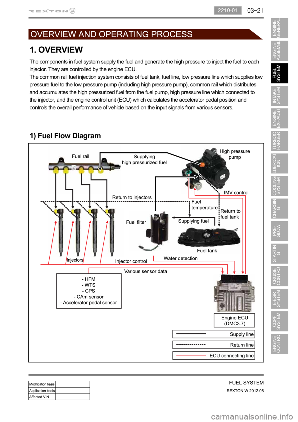
The components in fuel system supply the fuel and generate the high pressure to inject the fuel to each
injector. They are controlled by the engine ECU.
The common rail fuel injection system consists of fuel tank, fuel line, low pressure line which supplies low
pressure fuel to the low pressure pump (including high pressure pump), common rail which distributes
and accumulates the high pressurized fuel from the fuel pump, high pressure line which connected to
the injector, and the engine control unit (ECU) which calculates the accelerator pedal position and
controls the overall performance of vehicle based on the input signals from various sensors.
1) Fuel Flow Diagram
Page 336 of 600

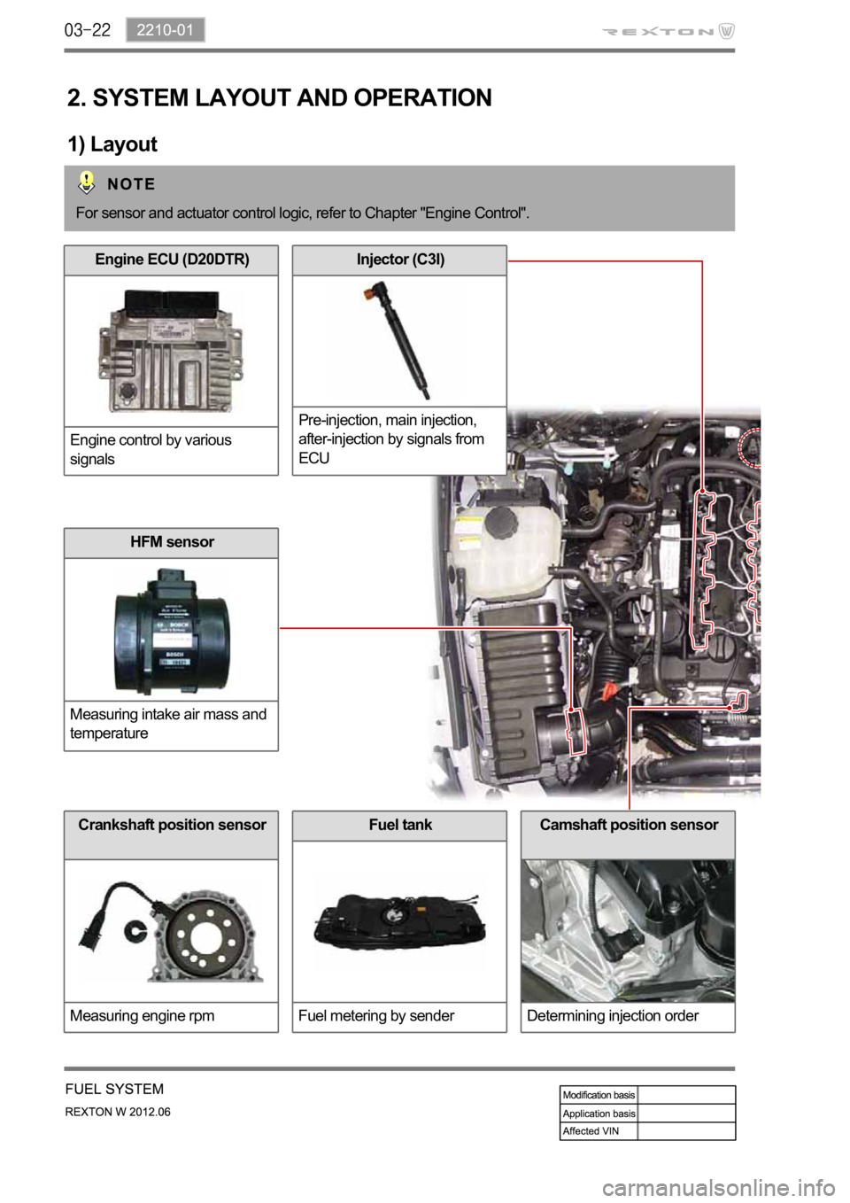
Fuel tank
Fuel metering by sender
2. SYSTEM LAYOUT AND OPERATION
1) Layout
For sensor and actuator control logic, refer to Chapter "Engine Control".
Engine ECU (D20DTR)
Engine control by various
signals
Crankshaft position sensor
Measuring engine rpm
Injector (C3I)
Pre-injection, main injection,
after-injection by signals from
ECU
HFM sensor
Measuring intake air mass and
temperature
Camshaft position sensor
Determining injection order
Page 340 of 600

The engine ECU calculates the accelerator pedal based on the input signals from various sensors, and
controls the overall operation of the vehicle.
The ECU receives the signals from various sensor through data line, and performs effective air-fuel ratio
control based on these signals.
The crankshaft speed (position) sensor measures the engine speed, and the camshaft speed (position)
sensor determines the order of injections, and the ECU detects the amount of the accelerator pedal
depressed (driver's will) by receiving the electrical signals from the accelerator pedal sensor.
The mass air flow sensor detects the volume of intake air and sends the value to the ECU.
The major function of the ECU is controlling air-fuel ratio to reduce the emission level (EGR valve control)
by detecting instantaneous air flow change with the signals from the mass air flow sensor.
Also, the ECU uses the signals from the coolant temperature & air temperature sensors, booster pressure
sensor, atmospheric pressure sensor to: a) determine injection starting point and set value for pilot
injection, and b) deal with various operations and variable conditions.
Page 368 of 600

1914-01
1. SYSTEM DESCRIPTION OF E-VGT
(Electric-Variable Geometry Turbine)
The E-VGT turbocharger has one shaft where at each ends are installed with two turbines having
different angles to connect one end of housing to the intake manifold and the other end to the exhaust
manifold. As the turbine, at exhaust end, is rotated by exhaust gas pressure the impeller, at intake end,
gets rotated to send air around center of the impeller, being circumferentially accelerated by the
centrifugal force, into the diffuser. The air, which has been introduced to the diffuser having a passage
with big surface, transforms its speed energy into the pressure energy while being supplied to the
cylinder improving the volume efficiency. Also, the exhaust efficiency improves as the exhaust turbine
rotates. The turbocharger is often referred to as the exhaust turbine turbocharger.
1) Overview
Diffuser: With the meaning of spreading out it is a device that transforms fluid's speed energy into the
pressure energy by enlarging the fluid's passage to slow down the flow.
The E-VGT system installed to the D20DTR engine variably controls the passages of the turbine
housing to regulate the flow rate of the exhaust gas. The actuator of E-VGT is a DC motor actuator (E-
Actuator) which controls more quickly and precisely than the previous vacuum type actuator.
The engine ECU controls the E-Actuator electronically as follows:
At low speed: Narrows the flow passage for the exhaust gas, resulting in increasing the flow
speed of the exhaust gas and running the turbine quickly and powerfully.
At high speed: Expands the flow passage for the exhaust gas, resulting in increasing the mass
flow of the exhaust gas and running the turbine more powerfully. -
-
Page 370 of 600

1914-01
E-VGT turbocharger
Improves engine power
2. COMPONENTS
Engine ECU (D20DTR)
E-VGT duty controlAccelerator pedal position
sensor
Transfers driver's will to
accelerate to ECU
Atmospheric pressure, RPM
signal
HFM sensor
Improves the engine powerCoolant temperature sensor
Operates the VGT according to
engine warm-upT-MAP sensor
Booster pressure and
temperature
Page 376 of 600

1543-00
1. SYSTEM DESCRIPTION
1) Overview
The lubrication system supplies oil to each lubrication section to prevent friction and wear and to remove
heat from the friction part. As the engine runs, frictional heat is generated on each lubrication section. If
this condition persists, the bearing can be burned and stuck.
In other words, it creates an oil film on each sliding surface to convert solid friction to liquid friction in order
to minimize wear and prevent temperature increasing on the friction part.
For the D20DTF engine with no oil pressure switch, the engine ECU receives the low engine oil level
signal from the oil level sensor and communicates with the instrument cluster through the CAN
communication to turn on the warning lamp.
2) Components
Oil coolerOil dipstick gaugeOil pump
Oil filter moduleOil pressure switchOil pan
Page 384 of 600

1520-00
Electric fan
Circulates the fresh air forcibly to exchange heat
with the radiator core fin.
Radiator
Releases heat through fins and cools down the hot
coolant as the coolant passes through the tube of the
radiator core.
Coolant temperature sensor
Measures the coolant
temperature and sends the
result to the engine ECU.
Page 397 of 600

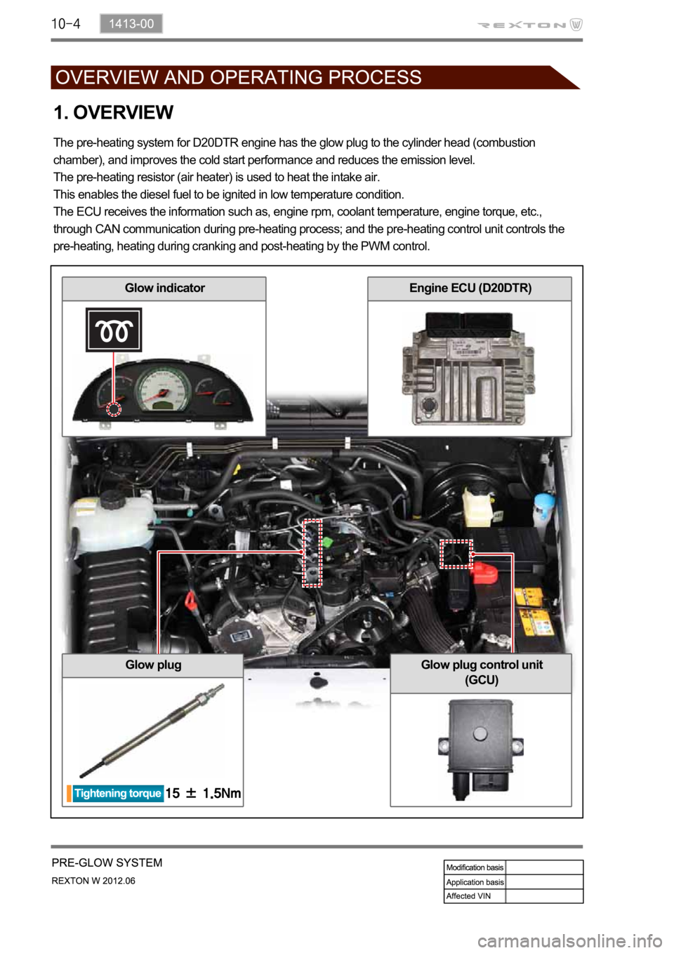
1. OVERVIEW
The pre-heating system for D20DTR engine has the glow plug to the cylinder head (combustion
chamber), and improves the cold start performance and reduces the emission level.
The pre-heating resistor (air heater) is used to heat the intake air.
This enables the diesel fuel to be ignited in low temperature condition.
The ECU receives the information such as, engine rpm, coolant temperature, engine torque, etc.,
through CAN communication during pre-heating process; and the pre-heating control unit controls the
pre-heating, heating during cranking and post-heating by the PWM control.
Glow plug
Glow indicatorEngine ECU (D20DTR)
Glow plug control unit
(GCU)
Page 400 of 600

1413-00
Voltage pattern in actual stepGCU PWM control
4) Operation
Glow plug is installed in the cylinder head. It enhances the cold starting performance and reduces the
exhaust gas during cold starting.
ECU receives the data (engine rpm, coolant temperature, vehicle speed) through CAN lines. Based on the
data, GCU controls the pre-glow, cranking and post-glow. It also checks the glow plugs, and sends the
result to ECU.
Duty control area:
Between 5 and 100%
Frequency: 20 Hz
1.
2.
3.
(1) Temperature/Current Properties of GCU
FETs (similar to transistor) for each cylinder are integrated in GCU. During the pre-glow period, battery
voltage is supplied to the glow plugs directly to heat them rapidly.
After getting the desired temperature by pre-glowing, the temperature is controlled by duty ratio. 1.
2.
3.
Frequency:
20~33Hz
PWM control duty
ratio
- 1st step: 100%
- 2nd step: 35%
- 3rd step: 23%
This describes the voltage supplying types to glow plugs. This shows the supplying voltage and
time by GCU in each step. The 3rd
step is the period to keep the
temperature.
(2) Operation Type of GCU
Page 401 of 600

(3) Operation
Pre-Glow: Step 1
If normal communication with the ECU is established 2 seconds after the power is supplied to the IGN
terminal from the battery, the GCU supplies the battery power to raise the temperature of the glow plug
- The time for pre-heating is controlled by the ECU.
Input power VB(V) Arrival time T1(s)
68.27
75.8
84.1
93.15
10 2.4
11 1.95
1.9
If the input power (VB) is 11.5 V or less, the GCU supplies the battery power for arrival time (T1).
If the input power (VB) is greater than 11.5 V, the GCU supplies the voltage of 11.5 V for arrival time
(T1). -
-
The time for pre-heating by coolant temperature can vary slightly depending on e.g. other vehicle
operation elements.