change time SSANGYONG NEW REXTON 2012 Service Manual
[x] Cancel search | Manufacturer: SSANGYONG, Model Year: 2012, Model line: NEW REXTON, Model: SSANGYONG NEW REXTON 2012Pages: 600, PDF Size: 73.29 MB
Page 212 of 600

1. FUEL FLOW OF D20DT (EURO 4) ENGINE
According to input signals from various sensors, engine ECU calculates driver's demand (position of the
accelerator pedal) and then controls overall operating performance of engine and vehicle on that time. ECU
receives the signals from sensors via data line and then performs effective engine air-fuel ratio controls
based on those signals. Engine speed is measured by crankshaft speed (position) sensor and camshaft
speed (position) sensor determines injection order and ECU detects driver's pedal position (driver's
demand) through electrical signal that is generated by variable resistance changes in accelerator pedal
sensor. HFM (Hot Film Air Mass) sensor detects intake air volume and sends the signals to ECU.
Especially, the engine ECU controls the air-fuel ratio by recognizing instant air volume changes from air flow
sensor to decrease the emissions (EGR valve control). Furthermore, ECU uses signals from coolant
temperature sensor and air temperature sensor, booster pressure sensor and atmospheric pressure sensor
as compensation signal to respond to injection starting, pilot injection set values, various operations and
variables.
Page 305 of 600

4) Features
Reduced vibration noise from the powertrain by blocking the torsional vibrations
Enhanced vehicle silence and riding comforts: reduced engine torque fluctuation
Reduced shifting shocks
Smooth acceleration and deceleration -
-
-
-
5) Advantages
Improved torque response by using 3-stage type spring: Strengthens the torque response in all
ranges (low, medium, and high speed) by applying respective spring constant at each range.
Stable revolution of the primary and secondary wheel by using planetary gear: Works as auxiliary
damper against spring changes
Less heat generation due to no direct friction against spring surface: Plastic material is covered on
the spring outer surface
Increased durability by using plastic bushing (extends the lifetime of grease) -
-
-
-
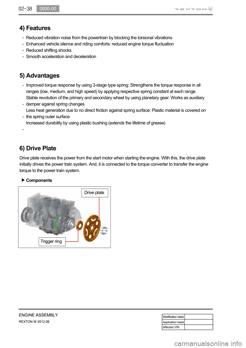
6) Drive Plate
Drive plate receives the power from the start motor when starting the engine. With this, the drive plate
initially drives the power train system. And, it is connected to the torque converter to transfer the engine
torque to the power train system.
Trigger ring
Drive plate
Components
Page 374 of 600

1543-00
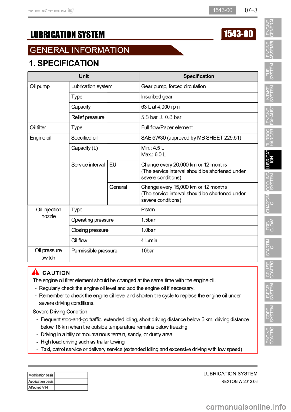
1. SPECIFICATION
The engine oil filter element should be changed at the same time with the engine oil.
Regularly check the engine oil level and add the engine oil if necessary.
Remember to check the engine oil level and shorten the cycle to replace the engine oil under
severe driving conditions. -
-
Severe Driving Condition
Frequent stop-and-go traffic, extended idling, short driving distance below 6 km, driving distance
below 16 km when the outside temperature remains below freezing
Driving in a hilly or mountainous terrain, sandy, or dusty area
High load driving such as trailer towing
Taxi, patrol service or delivery service (extended idling and excessive driving with low speed) -
-
-
-
Unit Specification
Oil pump Lubrication system Gear pump, forced circulation
Type Inscribed gear
Capacity 63 L at 4,000 rpm
Relief pressure
Oil filter Type Full flow/Paper element
Engine oil Specified oil SAE 5W30 (approved by MB SHEET 229.51)
Capacity (L) Min.: 4.5 L
Max.: 6.0 L
Service interval Change every 15,000 km or 12 months (But, shorten
the service interval under severe condition)
Oil injection
nozzleType Piston
Operating pressure 1.5bar
Closing pressure 1.0bar
Oil flow 4 L/min
Permissible pressure 10bar
Unit Specification
Oil pump Lubrication system Gear pump, forced circulation
Type Inscribed gear
Capacity 63 L at 4,000 rpm
Relief pressure
Oil filter Type Full flow/Paper element
Engine oil Specified oil SAE 5W30 (approved by MB SHEET 229.51)
Capacity (L) Min.: 4.5 L
Max.: 6.0 L
Service interval EU Change every 20,000 km or 12 months
(The service interval should be shortened under
severe conditions)
General Change every 15,000 km or 12 months
(The service interval should be shortened under
severe conditions)
Oil pressure
switch
Page 447 of 600

0000-00
2) ECU Control
(1) Function
a. ECU Function
ECU receives and analyzes signals from various sensors and then modifies those signals into
permissible voltage levels and analyzes to control respective actuators.
ECU microprocessor calculates injection period and injection timing proper for engine piston speed and
crankshaft angle based on input data and stored specific map to control the engine power and emission
gas.
Output signal of the ECU microprocessor drives pressure control valve to control the rail pressure and
activates injector solenoid valve to control the fuel injection period and injection timing; so controls
various actuators in response to engine changes. Auxiliary function of ECU has adopted to reduce
emission gas, improve fuel economy and enhance safety, comforts and conveniences. For example,
there are EGR, booster pressure control, autocruise (export only) and immobilizer and adopted CAN
communication to exchange data among electrical systems (automatic T/M and brake system) in the
vehicle fluently. And Scanner can be used to diagnose vehicle status and defectives.
water and electromagnetism and there should be no mechanical shocks.
To control the fuel volume precisely under repeated injections, high current should be applied instantly
so there is injector drive circuit in the ECU to generate necessary current during injector drive stages.
Current control circuit divides current applying time (injection time) into full-in-current-phase and hold-
current-phase and then the injectors should work very correctly under every working condition.
b. Control Function
Controls by operating stages
To make optimum combustion under every operating stage, ECU should calculate proper injection
volume in each stage by considering various factors.
Starting injection volume control
During initial starting, injecting fuel volume will be calculated by function of temperature and engine
cranking speed. Starting injection continues from when the ignition switch is turned to ignition
position to till the engine reaches to allowable minimum speed.
Driving mode control
If the vehicle runs normally, fuel injection volume will be calculated by accelerator pedal travel and
engine rpm and the drive map will be used to match the drivers inputs with optimum engine power. -
-
-
Page 455 of 600

0000-00
B. Driver Demand
The driver demand is the translation of the pedal position into the fuel demand. It is calculated as a
function of the pedal position and of the engine speed. The driver demand is filtered in order to limit the
hesitations caused by rapid changes of the pedal position. A mapping determines the maximum fuel
which can be injected as a function of the driver demand and the rail pressure. Since the flow is
proportional to the injection time and to the square root of the injection pressure, it is necessary to limit
the flow according to the pressure in order to avoid extending the injection for too long into the engine
cycle. The system compares the driver demand with this limit and chooses the smaller of the 2 values.
The driver demand is then corrected according to the coolant temperature. This correction is added to
the driver demand.