SSANGYONG NEW REXTON 2012 Service Manual
NEW REXTON 2012
SSANGYONG
SSANGYONG
https://www.carmanualsonline.info/img/67/57514/w960_57514-0.png
SSANGYONG NEW REXTON 2012 Service Manual
Page 169 of 600
Font Side
7910-01 Radiator Grille
- Changed the mounting type
(from on hood to on bumper).
- Changed the radiator grill design.
8310-01 Head Lamp
- Changed the head lamp design and functions.
- Turn signal lamp integrated with front fog lamp
1. EXTERIOR
7871-01 Front Bumper and Front PAS Sensor
- Changed the front bumper design according to the design changes of front combination lamp
and radiator grille.
- Changed the location of front PAS sensor.
Head lamp -
Low beam
Turn signal/Position lamp
Head lamp -
High beam Head lamp -
High beamHead lamp - Low beam
Position lamp (LED)
Front fog lamp
Front PAS sensorTurn signal/Front fog lamp
Front PAS sensor
Page 173 of 600
7881-01 Rear Bumper and Rear PAS Sensor
- Changed the rear bumper design.
Rear PAS sensorRear PAS sensor
Rear Side
7950-39 Quarter Badge
- Installed the brand logo on LH rear quarter
panel (Rexton W).
8912-26 Audio Antenna
- Changed the antenna type from shark type to pole
type.
Page 180 of 600
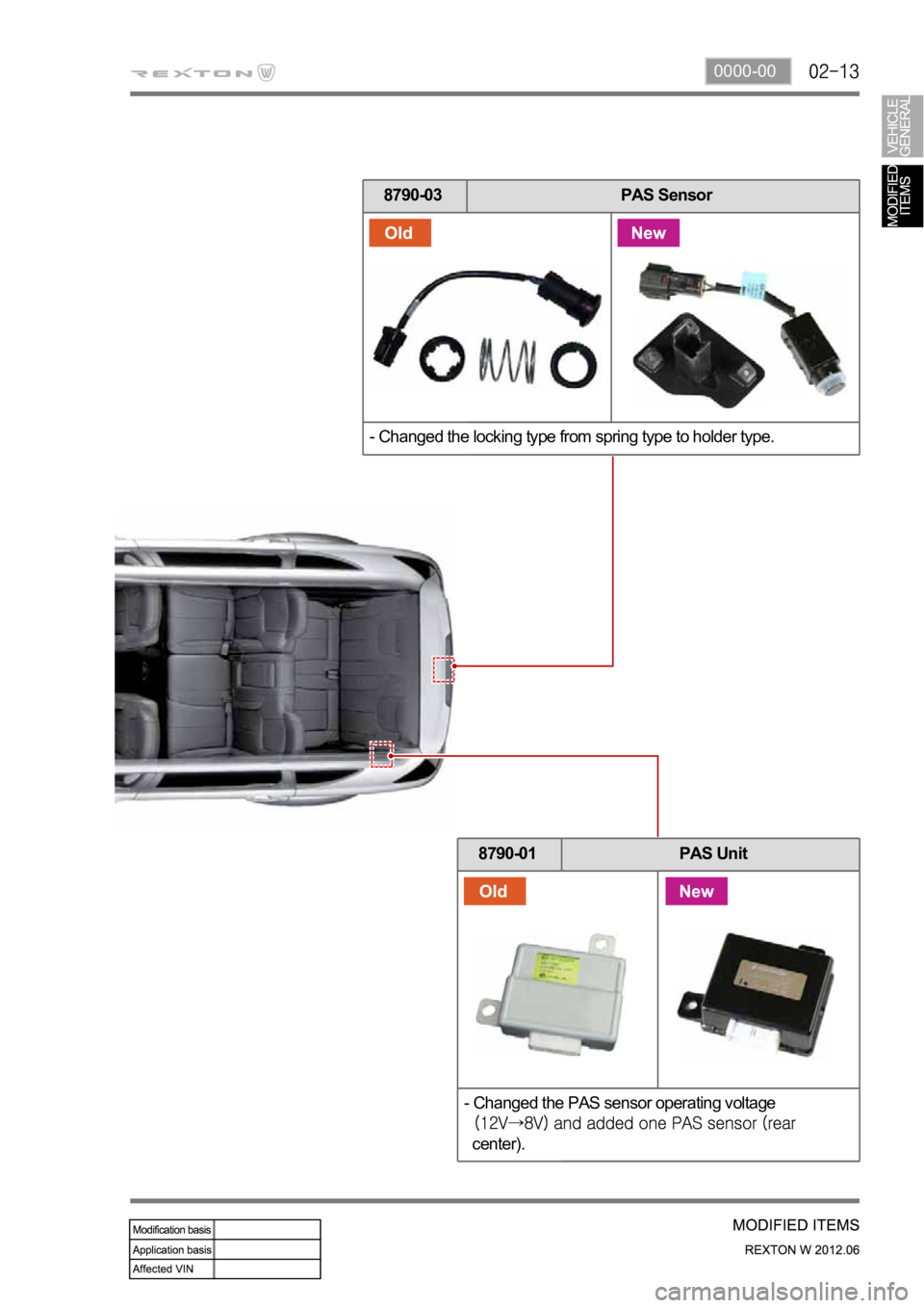
0000-00
8790-03 PAS Sensor
- Changed the locking type from spring type to holder type.
8790-01 PAS Unit
- Changed the PAS sensor operating voltage
center).
Page 184 of 600
0000-00
Knock sensor (one) and
water temperature sensor
Fuel rail sensor (common
rail)
1. LOCATION OF MAJOR SENSORS ON ENGINE
Major sensors and devices
InjectorGlow plugCommon rail
Camshaft position sensorBoost pressure sensor
Crankshaft position
sensor
HP pumpCommon rail
Injector
Turbocharger vacuum
modulator
Page 185 of 600
2. ENGINE ACCESSORIES RELATED TO ECU
HFM sensor (HFM 6.0)
To control the engine more precisely, new
functions such as digital signal for intake air mass
have been introduced.
Engine ECU
Location
Page 186 of 600
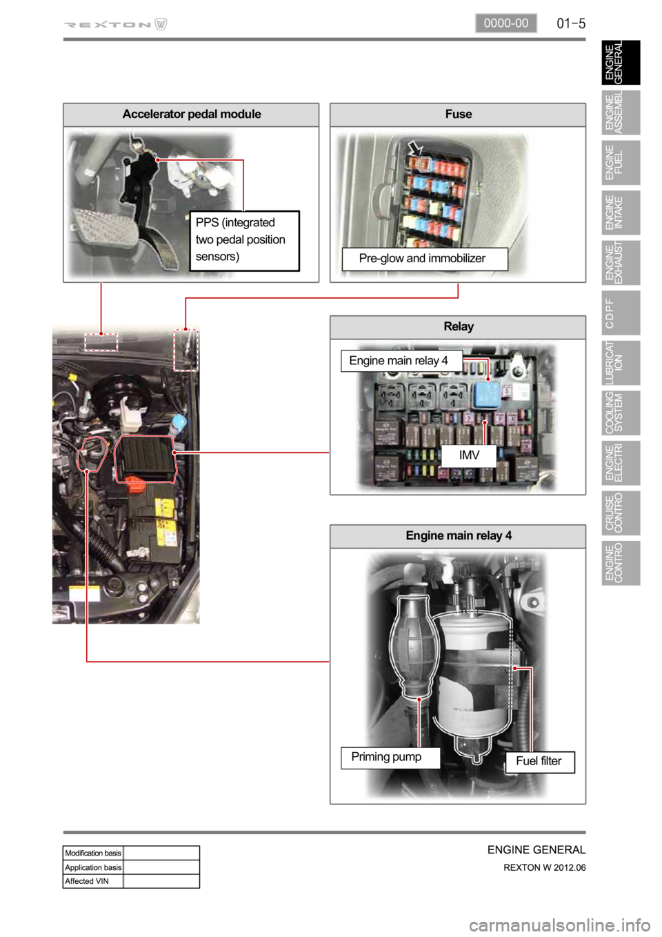
0000-00
Accelerator pedal moduleFuse
Relay
Engine main relay 4
PPS (integrated
two pedal position
sensors)
Pre-glow and immobilizer
Engine main relay 4
IMV
Priming pumpFuel filter
Page 188 of 600
0000-00
Turbocharger intercooler
4. LAYOUT OF INTAKE SYSTEM
HFM sensor (HFM 6.0)
Turbocharger
Supplying the compressed air by turbocharger
Air cleaner
Turbocharger
Turbocharger
Plug in sensor
Air
cleanerTurbochargerProtension graph
Temperature
sensor
Air cleaner
Intake manifold
Coolant port To respective cylinder
From
intercoolerVGT control
actuator
Exhaust gas
Throttle body
Engine operating: Flap
openEngine stopped:
Flap closed
Intake duct
Intake duct
Boost pressure
sensor
Power
Voltage outputGround
Page 195 of 600
InjectorFuel filter and priming pump
8. LAYOUT OF FUEL SYSTEM
Components
IMV connector
Pressure sensor
in fuel rail
High pressure
fuel pipe
Fuel pipe
Common rail IMV connector
HP pump
Priming pumpFuel filter
Connector
Returned fuel
from HP pumpFuel filter
Fuel tank
HP pump
Fuel tank
Fuel return port
Low pressure fuel supply portVenturi
Fuel return portFuel temperature
sensor
IMV valve
IMV connectorHigh pressure fuel
supply port
(with orifice)
Page 210 of 600
0000-00
D20DT Engine Remarks
To enhance the EGR performance by
making the temperature of exhaust
gas into the intake manifold down, the
EGR cooler has been introduced. *EGR cooler
EGR GasCoolant
The throttle body and boost pressure
sensor have been installed on the
intake manifold. *
Intake manifold
Throttle
bodyBoost pressure sensor
Cylinder head
Coolant portTo enhance the cooling performance,
the coolant port has been introduced. *
To enhance the cooling performance,
the coolant passage has been made
in the cylinder block. *
Cylinder head gasket
Coolant passage
Page 212 of 600

1. FUEL FLOW OF D20DT (EURO 4) ENGINE
According to input signals from various sensors, engine ECU calculates driver's demand (position of the
accelerator pedal) and then controls overall operating performance of engine and vehicle on that time. ECU
receives the signals from sensors via data line and then performs effective engine air-fuel ratio controls
based on those signals. Engine speed is measured by crankshaft speed (position) sensor and camshaft
speed (position) sensor determines injection order and ECU detects driver's pedal position (driver's
demand) through electrical signal that is generated by variable resistance changes in accelerator pedal
sensor. HFM (Hot Film Air Mass) sensor detects intake air volume and sends the signals to ECU.
Especially, the engine ECU controls the air-fuel ratio by recognizing instant air volume changes from air flow
sensor to decrease the emissions (EGR valve control). Furthermore, ECU uses signals from coolant
temperature sensor and air temperature sensor, booster pressure sensor and atmospheric pressure sensor
as compensation signal to respond to injection starting, pilot injection set values, various operations and
variables.


