engine oil SSANGYONG RODIUS 2005 Service Manual
[x] Cancel search | Manufacturer: SSANGYONG, Model Year: 2005, Model line: RODIUS, Model: SSANGYONG RODIUS 2005Pages: 502, PDF Size: 70.43 MB
Page 110 of 502

01-3
ENGINE GENERAL
RODIUS 2005.07
0000-00
0000-00ENGINE GENERAL
1. COMPONENTS LOCATOR
1) FRONT VIEW
1. HFM sensor
2. Intake air duct
3. Resonance flap
4. Cylinder head cover
5. Exhaust camshaft
6. Intake camshaft
7. Cylinder head
8. Spark plug connector9. Valve tappet
10. Injector
11. Exhaust valve
12. Intake manifold
13. Connecting rod
14. Exhaust manifold
15. Crankshaft16. Engine mounting bracket
17. Starter
18. Crankcase
19. Oil pump sprocket
20. Oil strainer
21. Oil pan
22. Drain plug
Page 111 of 502

01-4
RODIUS 2005.07
0000-00
ENGINE GENERAL
2) SIDE VIEW
23. Camshaft adjuster
24. Cooling fan and viscous clutch
25. Piston
26. Flywheel of drive plate27. Oil pump drive chain
28. Oil return pipe
29. Timing chain
Page 112 of 502

01-5
ENGINE GENERAL
RODIUS 2005.07
0000-00
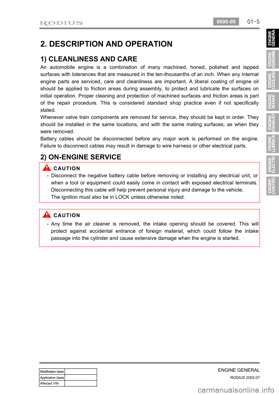
2. DESCRIPTION AND OPERATION
1) CLEANLINESS AND CARE
An automobile engine is a combination of many machined, honed, polished and lapped
surfaces with tolerances that are measured in the ten-thousanths of an inch. When any internal
engine parts are serviced, care and cleanliness are important. A liberal coating of enigne oil
should be applied to friction areas during assembly, to protect and lubricate the surfaces on
initial operation. Proper cleaning and protection of machined surfaces and friction areas is part
of the repair procedure. This is considered standard shop practice even if not specifically
stated.
Whenever valve train components are removed for service, they should be kept in order. They
should be installed in the same locations, and with the same mating surfaces, as when they
were removed.
Battery cables should be disconnected before any major work is performed on the engine.
Failure to disconnect cables may result in damage to wire harness or other electrical parts.
2) ON-ENGINE SERVICE
Disconnect the negative battery cable before removing or installing any electrical unit, or
when a tool or equipment could easily come in contact with exposed electrical terminals.
Disconnecting this cable will help prevent personal injury and damage to the vehicle.
The ignition must also be in LOCK unless otherwise noted. -
Any time the air cleaner is removed, the intake opening should be covered. This will
protect against accidental entrance of foreign material, which could follow the intake
passage into the cylinder and cause extensive damage when the engine is started. -
Page 115 of 502

02-4
RODIUS 2005.07
1113-01
ENGINE ASSEMBLY
2. COMPONENTS LOCATOR
1) FRONT VIEW
1. HFM sensor
2. Intake air duct
3. Resonance flap
4. Cylinder head cover
5. Exhaust camshaft
6. Intake camshaft
7. Cylinder head
8. Spark plug connector9. Valve tappet
10. Injector
11. Exhaust valve
12. Intake manifold
13. Connecting rod
14. Exhaust manifold
15. Crankshaft16. Engine mounting bracket
17. Starter
18. Crankcase
19. Oil pump sprocket
20. Oil strainer
21. Oil pan
22. Drain plug
Page 116 of 502

02-5
ENGINE ASSEMBLY
RODIUS 2005.07
1113-01
2) SIDE VIEW
23. Camshaft adjuster
24. Cooling fan and viscous clutch
25. Piston
26. Flywheel of drive plate27. Oil pump drive chain
28. Oil return pipe
29. Timing chain
Page 117 of 502

02-6
RODIUS 2005.07
1113-01
ENGINE ASSEMBLY
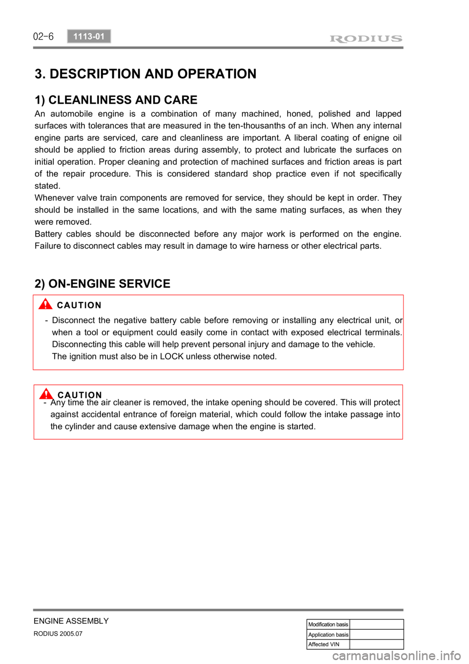
3. DESCRIPTION AND OPERATION
1) CLEANLINESS AND CARE
An automobile engine is a combination of many machined, honed, polished and lapped
surfaces with tolerances that are measured in the ten-thousanths of an inch. When any internal
engine parts are serviced, care and cleanliness are important. A liberal coating of enigne oil
should be applied to friction areas during assembly, to protect and lubricate the surfaces on
initial operation. Proper cleaning and protection of machined surfaces and friction areas is part
of the repair procedure. This is considered standard shop practice even if not specifically
stated.
Whenever valve train components are removed for service, they should be kept in order. They
should be installed in the same locations, and with the same mating surfaces, as when they
were removed.
Battery cables should be disconnected before any major work is performed on the engine.
Failure to disconnect cables may result in damage to wire harness or other electrical parts.
2) ON-ENGINE SERVICE
Disconnect the negative battery cable before removing or installing any electrical unit, or
when a tool or equipment could easily come in contact with exposed electrical terminals.
Disconnecting this cable will help prevent personal injury and damage to the vehicle.
The ignition must also be in LOCK unless otherwise noted. -
Any time the air cleaner is removed, the intake opening should be covered. This will protect
against accidental entrance of foreign material, which could follow the intake passage into
the cylinder and cause extensive damage when the engine is started. -
Page 136 of 502

0-3
ENGINE LUBRICATION SYSTEM
RODIUS 2005.07
9210-01
0000LUBRICATION SYSTEM
1. ENGINE OIL SPECIFICATION
1) components
1. Drain plug .................................... 25 Nm (18 lb-ft)
2. Oil filter3. Engine oil filler cap
4. Dipstick gauge
2) Specifications
Page 137 of 502

0-4
RODIUS 2005.07
9210-01
ENGINE LUBRICATION SYSTEM
3) Replacement
Install the socket wrench A9910 0050A
(103 589 02 09 00) on the oil filter cover (2).
1.
Tighten the bolts on the socket wrench to
remove the screw cover.
Set a wrench on the bolt on the top of
socket wrench and turn it to remove the
oil filter cover.
Remove the oil filter element.
2.
3.
Wrap the used filter element with a shop
cloth so that the oil cannot drop on the floor.
Remove the drain plug (1) and drain the
engine oil completely.
4.
To drain the oil easily, remove the oil filler
cap (3).
Clean the drain plug and reinstall it.
5.
Replace the seal washer with new one.
Replace the O-ring (5) on the oil filter
cover with new one.
6.
When replacing, apply the engine oil on the
O-ring.
Insert new oil filter element into the oil
filter housing.
Temporarily tighten the oil filter cover (2)
by hands and then tighten it with the
socket wrench A9910 0050A
(103 589 02 09 00).
7.
8.
Pour the engine oil through the engine oil
filler hole. Run the engine and check for oil leakage
at normal operating temperature.
Stop the engine and wait for 5 minutes.
Check the oil level and add if necessary.
9.
10.
11.
Page 140 of 502

0-7
ENGINE LUBRICATION SYSTEM
RODIUS 2005.07
9210-01
1. OIL CIRCULATION
1. Oil pump
2. Oil gallery (to oil filter)
3. Oil filter
4. Oil pressure switch
5. Main oil gallery
6. Cylinder head closing cover
7. Oil gallery (at chain tensioner)
8. Oil non-return valve
9. Chain tensioner
10. Vent (chain tensioner)
11. Front closing cover (φ 17 mm)
12. Oil gallery (perpendicular to the shaft)
13. Ball (φ 6 mm)
14. Oil spray nozzle (timing chain)
15. Oil gallery (at cylinder head)
16. Ball (φ 15mm)
17. Oil restriction inner (φ 4mm)
18. Oil supply (to exhaust camshaft)19. Oil supply (to intake camshaft)
20. Oil supply (to exhaust camshaft bearing)
21. Oil supply (to intake camshaft bearing)
22. Oil gallery (oil supply to exhaust valve tappet)
23. Oil gallery (oil supply to intake valve tappet)
24. Camshaft closing cover
25. Ball (φ 8 mm)
26. Screw plug
27. Camshaft adjuster
28. Front closing cover (intake camshaft)
29. Front treaded bushing (exhaust camshaft)
30. Valve tappet
a. Oil gallery (from oil pump to oil filter)
b. Main oil gallery
c. Oil return line (oil returns to the oil pan when
replacing the filter element)
Page 147 of 502

08-9
ENGINE ELECTRIC SYSTEM
RODIUS 2005.07
1452-01
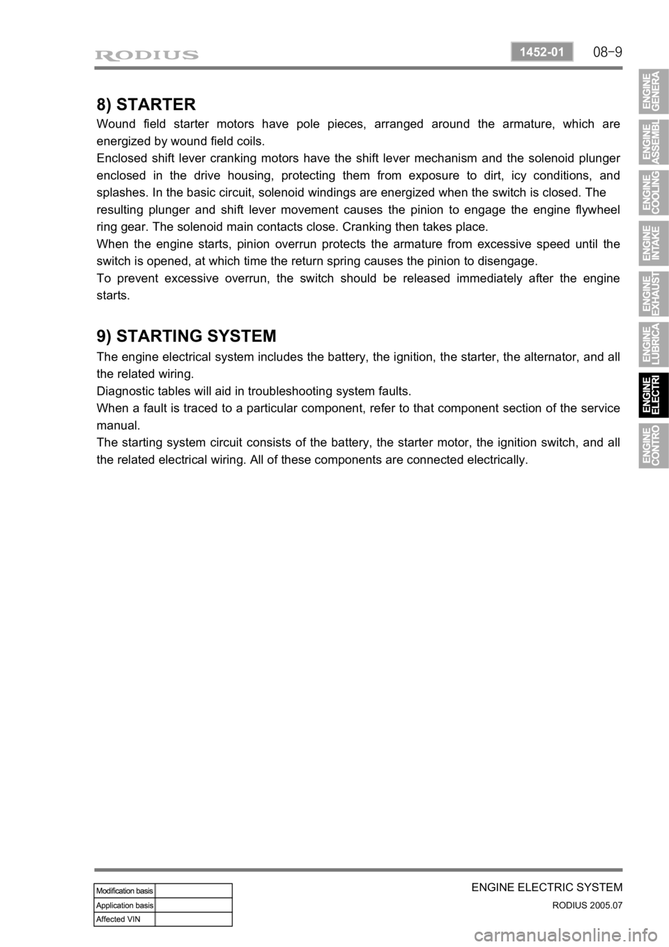
8) STARTER
Wound field starter motors have pole pieces, arranged around the armature, which are
energized by wound field coils.
Enclosed shift lever cranking motors have the shift lever mechanism and the solenoid plunge
r
enclosed in the drive housing, protecting them from exposure to dirt, icy conditions, and
splashes. In the basic circuit, solenoid windings are energized when the switch is closed. The
resulting plunger and shift lever movement causes the pinion to engage the engine flywheel
ring gear. The solenoid main contacts close. Cranking then takes place.
When the engine starts, pinion overrun protects the armature from excessive speed until the
switch is opened, at which time the return spring causes the pinion to disengage.
To prevent excessive overrun, the switch should be released immediately after the engine
starts.
9) STARTING SYSTEM
The engine electrical system includes the battery, the ignition, the starter, the alternator, and all
the related wiring.
Diagnostic tables will aid in troubleshooting system faults.
When a fault is traced to a particular component, refer to that component section of the service
manual.
The starting system circuit consists of the battery, the starter motor, the ignition switch, and all
the related electrical wiring. All of these components are connected electrically.