SSANGYONG RODIUS 2005 Service Manual
RODIUS 2005
SSANGYONG
SSANGYONG
https://www.carmanualsonline.info/img/67/57522/w960_57522-0.png
SSANGYONG RODIUS 2005 Service Manual
Trending: brake, ECU, ignition, high beam, low oil pressure, height, air filter
Page 1 of 502
GENERAL INFORMATION
0000-00
GENERAL INFORMATION
GENERAL INFORMATION1. HOW TO READ ELECTRICAL WIRING
DIAGRAM...............................................
3
Page 2 of 502
Page 3 of 502
0-3
GENERAL INFORMATION
RODIUS 2005.07
0000-00
GENERAL INFORMATION
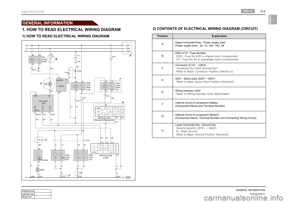
1. HOW TO READ ELECTRICAL WIRING DIAGRAM
Position Explanation
A- Upper horizontal lines : Power supply lines
- Power supply lines : 30, 15, 15A, 15C, 58
B- Ef20 or F2 : Fuse Number
·Ef20 : Fuse No #20 in engine room compartment
·F2 : Fuse No #2 in passenger room compartment
C- Connector (C101 ~ C903)
·Connector No C203 terminal No1
·Refer to Major Connector Position (Section 2)
D- S201 : Splice pack (S201 ~ S207)
·Refer to Major Splice Pack Position (Section2)
E- Wiring Harness Color
·Refer to Wiring Harness Color Abbreviation
F- Internal circuit of component (Relay)
(Component Name and Terminal Number)
G- Internal circuit of component (Switch)
(Component Name, Terminal Number and Connecting Wiring Circuit)
H- Lower horizontal line : Ground line
·Ground position (G101 ~ G402)
·B : Body Ground
·Refer to Major Ground Position (Section2)
1) HOW TO READ ELECTRICAL WIRING DIAGRAM2) CONTENTS OF ELECTRICAL WIRING DIAGRAM (CIRCUIT)
Page 4 of 502
0-4RODIUS 2005.07
0000-00
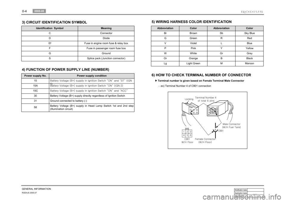
GENERAL INFORMATION3) CIRCUIT IDENTIFICATION SYMBOL
Identification Symbol Meaning
C Connector
D Diode
Ef Fuse in engine room fuse & relay box
F Fuse in passenger room fuse box
G Ground
S Splice pack (Junction connector)
5) WIRING HARNESS COLOR IDENTIFICATION
Abbreviation Color Abbreviation Color
Br Brown Sb Sky Blue
G Green R Red
V Violet L Blue
P Pink Y Yellow
W White Gr Gray
Or Orange B Black
Lg Light Green M Maroon
6) HOW TO CHECK TERMINAL NUMBER OF CONNECTOR
Terminal number is given based on Female Terminal Male Connector ▶
ex) Terminal Number 4 of C901 connection -
Power supply No. Power supply condition
15<00690088009b009b008c009900a00047007d00960093009b0088008e008c0047004f0069005200500047009a009c00970097009300a000470090009500470070008e00950090009b0090009600950047007a009e0090009b008a008f004702c80076007502
c9004700880095008b004702c8007a007b02c90047004f0070>GN
1)
15A<00690088009b009b008c009900a00047007d00960093009b0088008e008c0047004f0069005200500047009a009c00970097009300a000470090009500470070008e00950090009b0090009600950047007a009e0090009b008a008f004702c80076007502
c90047004f0070006e0075004700590050>
15C<00690088009b009b008c009900a00047007d00960093009b0088008e008c0047004f0069005200500047009a009c00970097009300a000470090009500470070008e00950090009b0090009600950047007a009e0090009b008a008f004702c80076007502
c9004700880095008b004702c80068006a006a02c9>
30 Battery Voltage (B+) supply directly regardless of Ignition Switch
31 Ground connected to battery (-)
58Battery Voltage (B+) supply in Head Lamp Switch 1st and 2nd step
(Illumination circuit)4) FUNCTION OF POWER SUPPLY LINE (NUMBER)
Page 5 of 502
0-5
GENERAL INFORMATION
RODIUS 2005.07
0000-00
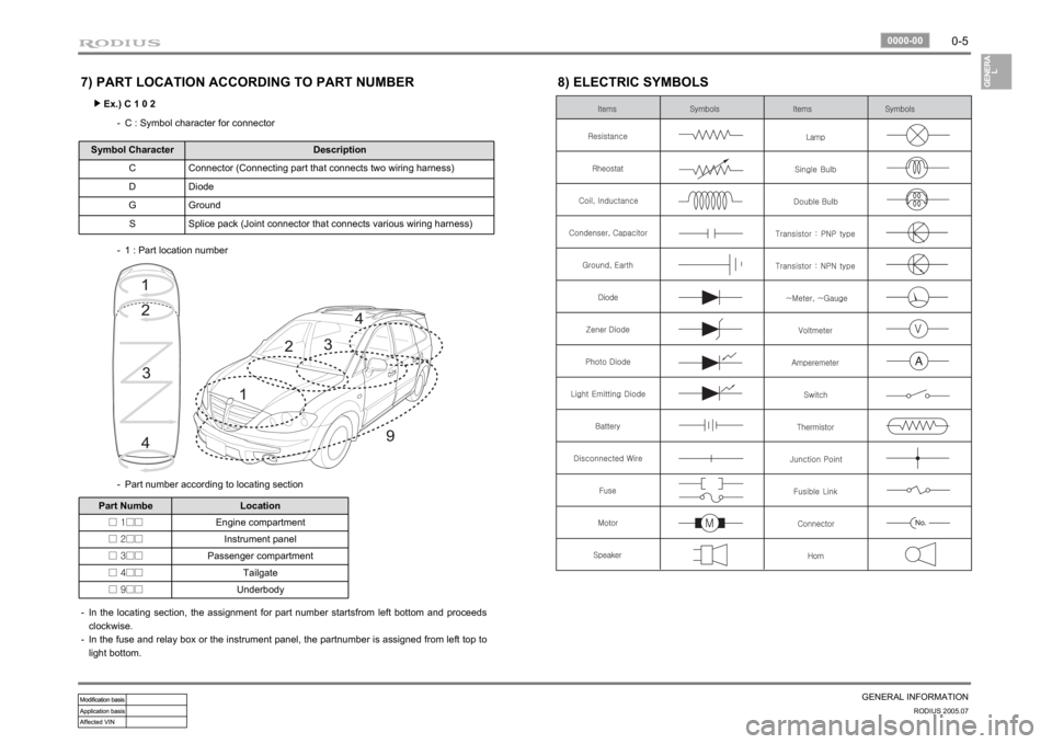
7) PART LOCATION ACCORDING TO PART NUMBER
Ex.) C 1 0 2 ▶
C : Symbol character for connector -
Symbol Character Description
C Connector (Connecting part that connects two wiring harness)
D Diode
G Ground
S Splice pack (Joint connector that connects various wiring harness)
1 : Part location number -
Part number according to locating section -
Part Numbe Location
□ 1□□Engine compartment
□ 2□□Instrument panel
□ 3□□Passenger compartment
□ 4□□Tailgate
□ 9□□Underbody
In the locating section, the assignment for part number startsfrom left bottom and proceeds
clockwise.
In the fuse and relay box or the instrument panel, the partnumber is assigned from left top to
light bottom. -
-
8) ELECTRIC SYMBOLS
Page 6 of 502
Page 7 of 502
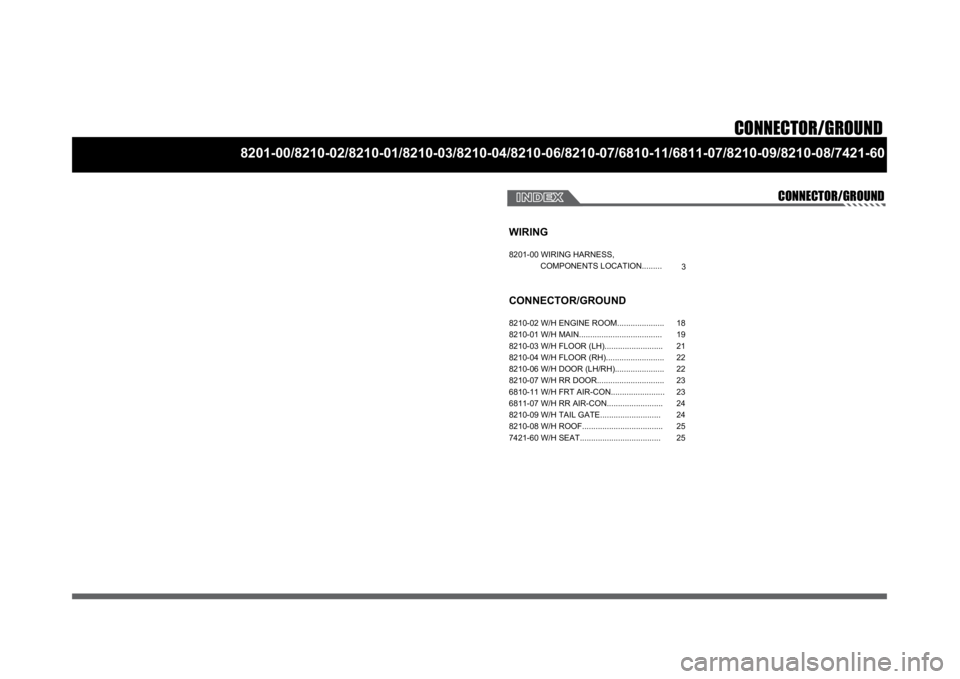
CONNECTOR/GROUND
8201-00/8210-02/8210-01/8210-03/8210-04/8210-06/8210-07/6810-11/6811-07/8210-09/8210-08/7421-60
CONNECTOR/GROUND
WIRING8201-00 WIRING HARNESS,
COMPONENTS LOCATION.........CONNECTOR/GROUND8210-02 W/H ENGINE ROOM.....................
8210-01 W/H MAIN.....................................
8210-03 W/H FLOOR (LH)..........................
8210-04 W/H FLOOR (RH)..........................
8210-06 W/H DOOR (LH/RH)......................
8210-07 W/H RR DOOR..............................
6810-11 W/H FRT AIR-CON........................
6811-07 W/H RR AIR-CON.........................
8210-09 W/H TAIL GATE...........................
8210-08 W/H ROOF....................................
7421-60 W/H SEAT....................................
318
19
21
22
22
23
23
24
24
25
25
Page 8 of 502
0-2RODIUS 2005.07
0000-00
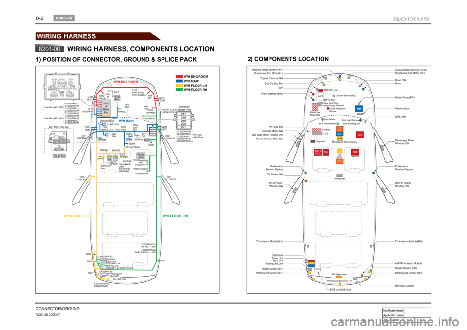
CONNECTOR/GROUNDWIRING HARNESS8201-00
WIRING HARNESS, COMPONENTS LOCATION
1) POSITION OF CONNECTOR, GROUND & SPLICE PACK
2) COMPONENTS LOCATION
Page 9 of 502
0-3
CONNECTOR/GROUND
RODIUS 2005.07
8201-00
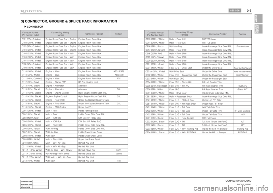
3) CONNECTOR, GROUND & SPLICE PACK INFORMATION
CONNECTOR ▶
Page 10 of 502
0-4RODIUS 2005.07
8201-00
CONNECTOR/GROUND
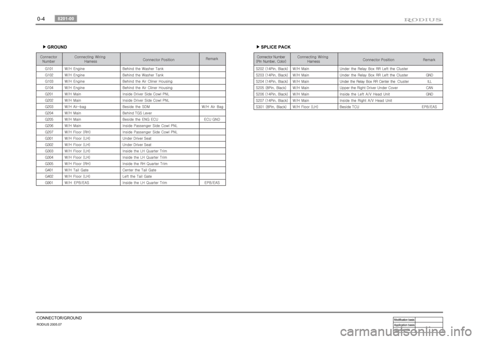
GROUND ▶
SPLICE PACK ▶
Trending: set clock, clock, wheel torque, brake pads, battery replacement, wipers, open hood
