fuse SSANGYONG RODIUS 2005 Service Manual
[x] Cancel search | Manufacturer: SSANGYONG, Model Year: 2005, Model line: RODIUS, Model: SSANGYONG RODIUS 2005Pages: 502, PDF Size: 70.43 MB
Page 3 of 502
0-3
GENERAL INFORMATION
RODIUS 2005.07
0000-00
GENERAL INFORMATION
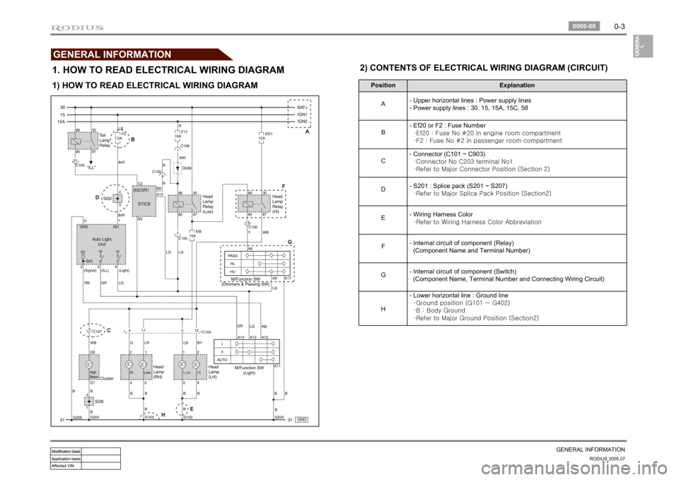
1. HOW TO READ ELECTRICAL WIRING DIAGRAM
Position Explanation
A- Upper horizontal lines : Power supply lines
- Power supply lines : 30, 15, 15A, 15C, 58
B- Ef20 or F2 : Fuse Number
·Ef20 : Fuse No #20 in engine room compartment
·F2 : Fuse No #2 in passenger room compartment
C- Connector (C101 ~ C903)
·Connector No C203 terminal No1
·Refer to Major Connector Position (Section 2)
D- S201 : Splice pack (S201 ~ S207)
·Refer to Major Splice Pack Position (Section2)
E- Wiring Harness Color
·Refer to Wiring Harness Color Abbreviation
F- Internal circuit of component (Relay)
(Component Name and Terminal Number)
G- Internal circuit of component (Switch)
(Component Name, Terminal Number and Connecting Wiring Circuit)
H- Lower horizontal line : Ground line
·Ground position (G101 ~ G402)
·B : Body Ground
·Refer to Major Ground Position (Section2)
1) HOW TO READ ELECTRICAL WIRING DIAGRAM2) CONTENTS OF ELECTRICAL WIRING DIAGRAM (CIRCUIT)
Page 4 of 502
0-4RODIUS 2005.07
0000-00
GENERAL INFORMATION3) CIRCUIT IDENTIFICATION SYMBOL
Identification Symbol Meaning
C Connector
D Diode
Ef Fuse in engine room fuse & relay box
F Fuse in passenger room fuse box
G Ground
S Splice pack (Junction connector)
5) WIRING HARNESS COLOR IDENTIFICATION
Abbreviation Color Abbreviation Color
Br Brown Sb Sky Blue
G Green R Red
V Violet L Blue
P Pink Y Yellow
W White Gr Gray
Or Orange B Black
Lg Light Green M Maroon
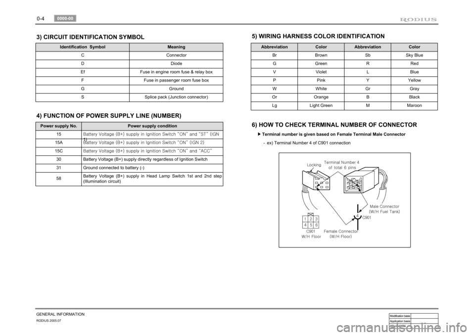
6) HOW TO CHECK TERMINAL NUMBER OF CONNECTOR
Terminal number is given based on Female Terminal Male Connector ▶
ex) Terminal Number 4 of C901 connection -
Power supply No. Power supply condition
15<00690088009b009b008c009900a00047007d00960093009b0088008e008c0047004f0069005200500047009a009c00970097009300a000470090009500470070008e00950090009b0090009600950047007a009e0090009b008a008f004702c80076007502
c9004700880095008b004702c8007a007b02c90047004f0070>GN
1)
15A<00690088009b009b008c009900a00047007d00960093009b0088008e008c0047004f0069005200500047009a009c00970097009300a000470090009500470070008e00950090009b0090009600950047007a009e0090009b008a008f004702c80076007502
c90047004f0070006e0075004700590050>
15C<00690088009b009b008c009900a00047007d00960093009b0088008e008c0047004f0069005200500047009a009c00970097009300a000470090009500470070008e00950090009b0090009600950047007a009e0090009b008a008f004702c80076007502
c9004700880095008b004702c80068006a006a02c9>
30 Battery Voltage (B+) supply directly regardless of Ignition Switch
31 Ground connected to battery (-)
58Battery Voltage (B+) supply in Head Lamp Switch 1st and 2nd step
(Illumination circuit)4) FUNCTION OF POWER SUPPLY LINE (NUMBER)
Page 5 of 502
0-5
GENERAL INFORMATION
RODIUS 2005.07
0000-00
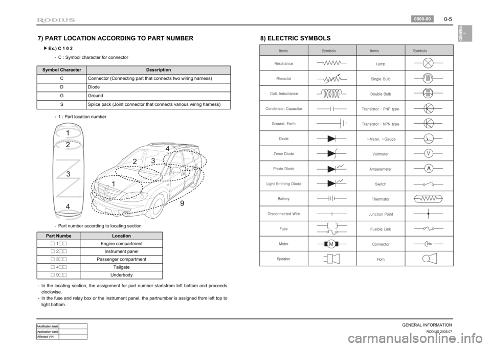
7) PART LOCATION ACCORDING TO PART NUMBER
Ex.) C 1 0 2 ▶
C : Symbol character for connector -
Symbol Character Description
C Connector (Connecting part that connects two wiring harness)
D Diode
G Ground
S Splice pack (Joint connector that connects various wiring harness)
1 : Part location number -
Part number according to locating section -
Part Numbe Location
□ 1□□Engine compartment
□ 2□□Instrument panel
□ 3□□Passenger compartment
□ 4□□Tailgate
□ 9□□Underbody
In the locating section, the assignment for part number startsfrom left bottom and proceeds
clockwise.
In the fuse and relay box or the instrument panel, the partnumber is assigned from left top to
light bottom. -
-
8) ELECTRIC SYMBOLS
Page 33 of 502
POWER DISTRIBUTION
8410-02/8410-05POWER DISTRIBUTION
FUSE/RELAY8410-02 ENGINE ROOM FUSE &
RELAY BOX.................................
8410-05 I.P FUSE & ICM BOX
(IP RELAY BOX)...........................ELECTRICITY DIVIDE8210-02 ENG ROOM FUSE BOX...............
8410-04 I.P FUSE BOX..............................3
5
7
11
Page 35 of 502
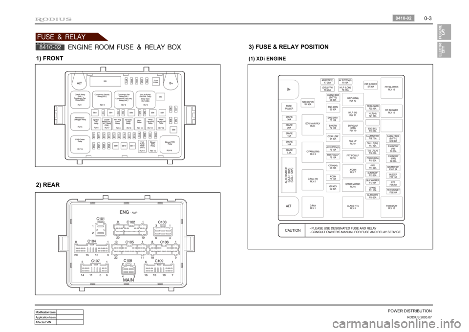
0-3
POWER DISTRIBUTION
RODIUS 2005.07
8410-02
FUSE & RELAY8410-02
ENGINE ROOM FUSE & RELAY BOX
1) FRONT2) REAR
3) FUSE & RELAY POSITION(1) XDi ENGINE
Page 36 of 502
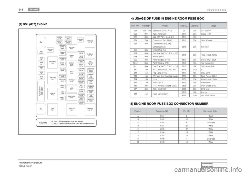
0-4RODIUS 2005.07
8410-02
POWER DISTRIBUTION
4) USAGE OF FUSE IN ENGINE ROOM FUSE BOX
5) ENGINE ROOM FUSE BOX CONNECTOR NUMBER
(2) GSL (G23) ENGINE
Page 37 of 502
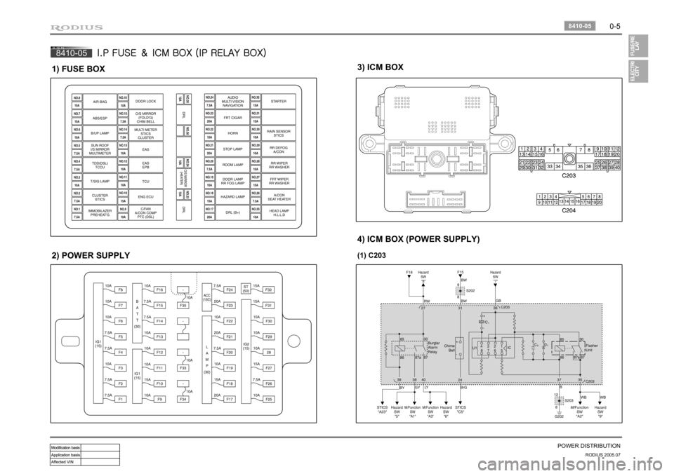
0-5
POWER DISTRIBUTION
RODIUS 2005.07
8410-05
8410-05
I.P FUSE & ICM BOX (IP RELAY BOX)
1) FUSE BOX2) POWER SUPPLY
3) ICM BOX4) ICM BOX (POWER SUPPLY)(1) C203
Page 39 of 502
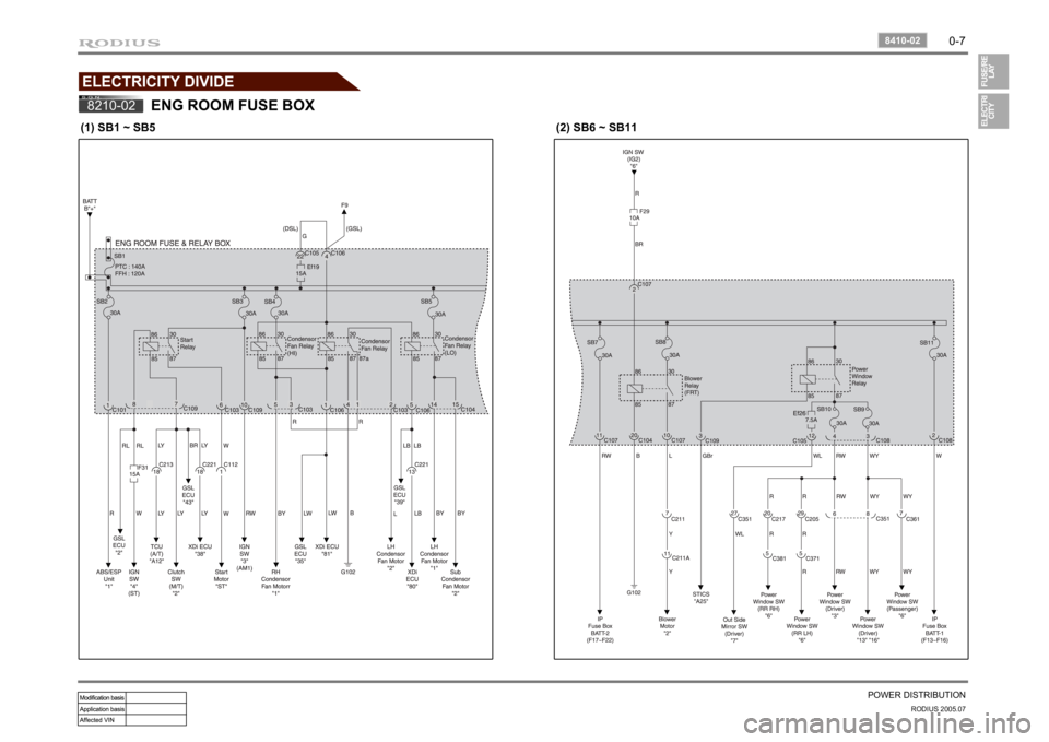
0-7
POWER DISTRIBUTION
RODIUS 2005.07
8410-02
ELECTRICITY DIVIDE8210-02
ENG ROOM FUSE BOX
(1) SB1 ~ SB5
(2) SB6 ~ SB11
Page 43 of 502

0-11
POWER DISTRIBUTION
RODIUS 2005.07
8410-04
8410-04
I.P FUSE BOX
(1) F1 ~ F5
(2) F6 ~ F12
Page 262 of 502
0-10
RODIUS 2005.07
4892-01
ABS SYSTEM
3. ON-VEHICLE SERVICE
(1) Electronic system service precautions
Take care to avoid electronic brake control module (HECU) circuit overloading. In testing for
opens or shorts, do not ground or apply voltage to any circuit unless instructed to do so by the
diagnostic procedure. Test circuits only with a high-impedance multi-meter. Never remove o
r
apply power to any control module with the ignition switch in the ON position. Always turn the
ignition to the OFF position before removing or connecting battery cables, fuses or connectors.
(2) General service precautions
Disconnect the HECU connector before performing any vehicle welding work using an electric
arc welder. Do not attempt to disassemble any component designated as nonserviceable. The
hydraulic modulator and the HECU can be seperated. (There is however no access to repai
r
the each components.)
(3) Bleeding system
Replacement modulators are shipped already filled and bled. In normal procedures requiring
removal of the modulator, such as to replace the HECU, air will not enter the modulator, and
normal bleeding will be all that is needed.
If air enters the hydraulic modulator, or if an unfilled modulator is installed, use the brake
bleeding program in the scan tool to bleed the modulator. Manual bleeding of the hydraulic
modulator is not possible.
1) Service Precautions
Brake Fluid may irritate eyes and skin. In case of contact, take the following actions:
Eye contact - rinse thoroughly with water.
Skin contact - wash with soap and water.
Ingestion - consult a physician immediately. -
-
-
To help avoid personal injury due to poor braking. DO NOT Tap into the vehicle’s
brake system to operate a trailer brake system.
When fasteners are removed, always reinstall them at the same location from which they
were removed. If a fastener needs to be replaced, use the correct part number fastener
for is not available, a fastener of equal size and strength (or stronger) may be used.
Fasteners that are not reused, and those requiring thread-locking compound will be
called out. The correct torque values must be used when installing fasteners that require
them. If the above procedures are not followed, parts or system damage could result.