display SSANGYONG RODIUS 2005 User Guide
[x] Cancel search | Manufacturer: SSANGYONG, Model Year: 2005, Model line: RODIUS, Model: SSANGYONG RODIUS 2005Pages: 502, PDF Size: 70.43 MB
Page 393 of 502

0-3
PARKING AID SYSTEM
RODIUS 2005.07
8790-04
8790-04PARKING ASSISTANCE SYSTEM
1. COMPONENT SPECIFICATIONS OF PARKING AID
SYSTEM
The parking aid system emits the supersonic wave signals from the sensors on the rear bumper
with a specific interval and detects the reflected signals from obstacles while the gear selecto
r
lever is in “R” position.
The number of displaying bars is decreased and the alarm interval becomes faster as the
obstacle approaches. This supplementary system is to secure the safety distance for parking.
Parking aid unit
Detecting type: Super sonic wave
Detecting distance: 25 ~ 120 cm
(distance between sensor and obstacle)
1)
Parking aid sensor
- Type: Piezo ceramic element
- Frequency: 40 KHz ± 2 KHz
- Detecting range (13.5 V)
* Horizontal: Min. 20° at 110 ± 5 cm Min. 1 00° at 50 ± 5 cm
* Vertical: Min. 20° at 110 ± 5 cm Min. 60° at 50 ± 5 cm
2)
Page 394 of 502

0-4
RODIUS 2005.07
8790-04
PARKING AID SYSTEM
Grear selector lever
Applies power to parking aid system
Rearview camera
1. COMPONENTS OF PARKING AID SYSTEM (PARKING AID SYSTEM + REARVIEW CAMERA)
1) REARVIEW CAMERA EQUIPPED VEHICLE
When moving the gear selector lever into R (Reverse) position while watching DVD or VCD, the
rearview appears on the front monitor but the rear monitor continuously shows current screen.
The video mode in front A/V system is changed to rearview monitoring mode. However, the
audio mode stays on.
The video mode in front A/V system resumes when shifting out from “R” position.
The audio and video mode in rear A/V system are not changed.
When selecting R position while A/V system is not in use:
Both monitors are automatically turned on to display rearview.
Both monitors are automatically turned off when shifting out from “R” position.
-
-
-
-
- When selecting R position while A/V system is in use:
Page 398 of 502

0-8
RODIUS 2005.07
8790-04
PARKING AID SYSTEM
3. OPERATIONS OF PARKING AID SYSTEM(PAS)
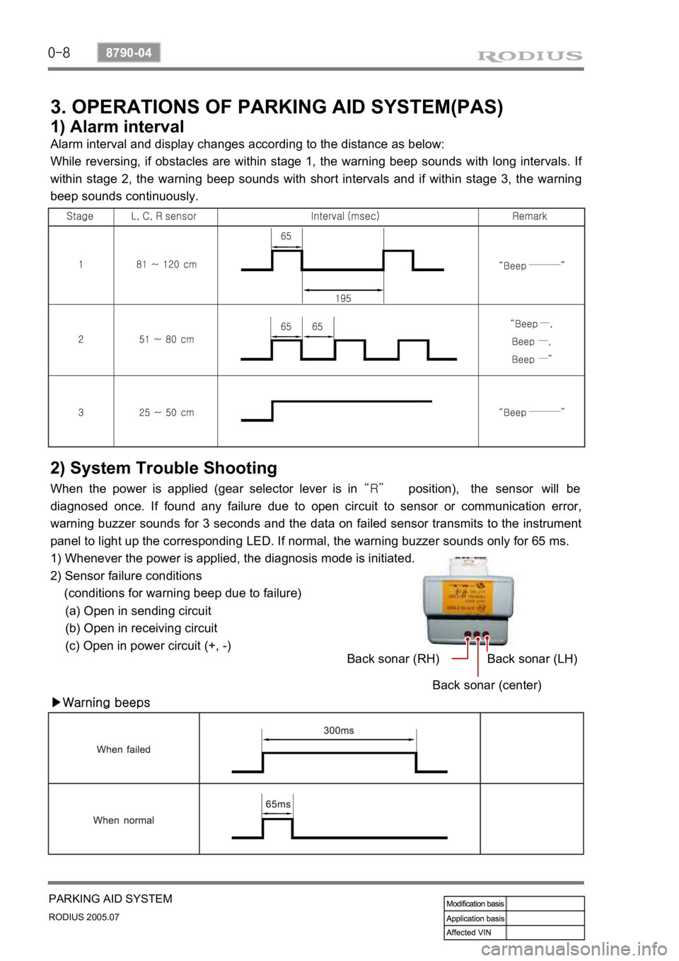
1) Alarm interval
Alarm interval and display changes according to the distance as below:
While reversing, if obstacles are within stage 1, the warning beep sounds with long intervals. I
f
within stage 2, the warning beep sounds with short intervals and if within stage 3, the warning
beep sounds continuously.
2) System Trouble Shooting
When the power is applied (gear selector lever is in “R” position), the sensor will be
diagnosed once. If found any failure due to open circuit to sensor or communication error,
warning buzzer sounds for 3 seconds and the data on failed sensor transmits to the instrument
panel to light up the corresponding LED. If normal, the warning buzzer sounds only for 65 ms.
1) Whenever the power is applied, the diagnosis mode is initiated.
2) Sensor failure conditions
(conditions for warning beep due to failure)
(a) Open in sending circuit
(b) Open in receiving circuit
(c) Open in power circuit (+, -)
▶Warning beepsBack sonar (RH)
Back sonar (center)Back sonar (LH)
Page 399 of 502

0-9
PARKING AID SYSTEM
RODIUS 2005.07
8790-04
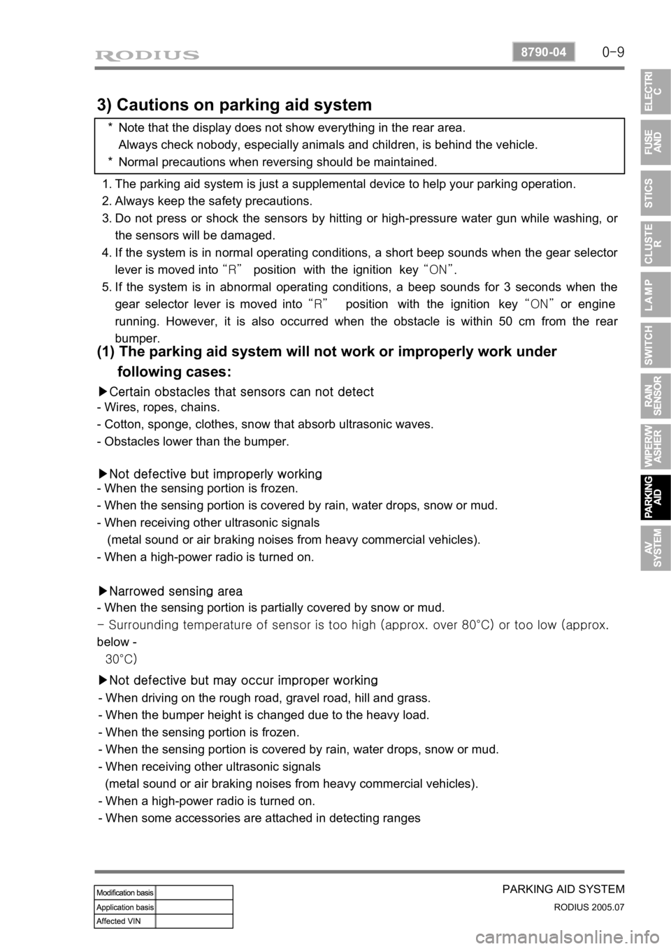
3) Cautions on parking aid system
Note that the display does not show everything in the rear area.
Always check nobody, especially animals and children, is behind the vehicle.
Normal precautions when reversing should be maintained. *
*
The parking aid system is just a supplemental device to help your parking operation.
Always keep the safety precautions.
Do not press or shock the sensors by hitting or high-pressure water gun while washing, o
r
the sensors will be damaged.
If the system is in normal operating conditions, a short beep sounds when the gear selecto
r
lever is moved into “R” position with the ignition key “ON”.
If the system is in abnormal operating conditions, a beep sounds for 3 seconds when the
gear selector lever is moved into “R” position with the ignition key “ON” or engine
running. However, it is also occurred when the obstacle is within 50 cm from the rea
r
bumper. 1.
2.
3.
4.
5.
(1) The parking aid system will not work or improperly work under
following cases:
▶Certain obstacles that sensors can not detect
- Wires, ropes, chains.
- Cotton, sponge, clothes, snow that absorb ultrasonic waves.
- Obstacles lower than the bumper.
▶Not defective but improperly working
- When the sensing portion is frozen.
- When the sensing portion is covered by rain, water drops, snow or mud.
- When receiving other ultrasonic signals
(metal sound or air braking noises from heavy commercial vehicles).
- When a high-power radio is turned on.
▶Narrowed sensing area
- When the sensing portion is partially covered by snow or mud.
<00540047007a009c009900990096009c0095008b00900095008e0047009b008c00940097008c00990088009b009c0099008c00470096008d0047009a008c0095009a0096009900470090009a0047009b009600960047008f0090008e008f0047004f008800
97009700990096009f005500470096009d008c00990047005f>0°C) or too low (approx.
below -
30°C)
▶Not defective but may occur improper working
- When driving on the rough road, gravel road, hill and grass.
- When the bumper height is changed due to the heavy load.
- When the sensing portion is frozen.
- When the sensing portion is covered by rain, water drops, snow or mud.
- When receiving other ultrasonic signals
(metal sound or air braking noises from heavy commercial vehicles).
- When a high-power radio is turned on.
- When some accessories are attached in detecting ranges
Page 401 of 502

0-11
PARKING AID SYSTEM
RODIUS 2005.07
8790-04
5. OPERATIONS OF REARVIEW CAMERA
This is a supplementary parking aid system to display the rearview when the gear selector lever
is moved into “R” position.
The audio and video mode in rear A/V system are not changed when selecting R position while
A/V system is in use.
The real distance is different from what you see in monitor because the camera uses
wide-angle lens.
Note that the display does not show everything in the rear area.
Keep the camera lens clean with a lens cleaner. -
-
-
Page 402 of 502

0-12
RODIUS 2005.07
8790-04
PARKING AID SYSTEM
6. OPERATIONAL PRINCIPLE OF REARVIEW CAMERA
In the rearview camera equipped vehicle, the monitors display when selecting “R”
position for safe parking. The operating conditions are as below:
1) General
When selecting R position while A/V system is in use:
The video mode in front A/V system is changed to rearview monitoring mode. However, the
audio mode stays on.
<007b008f008c0047009d0090008b008c0096004700940096008b008c0047009000950047008d009900960095009b004700680056007d0047009a00a0009a009b008c009400470099008c009a009c0094008c009a0047009e008f008c00950047009a008f00
90008d009b00900095008e00470096009c009b0047008d0099>om “R” position.
The audio and video mode in rear A/V system are not changed.
When selecting R position while A/V system is not in use:
Both monitors are automatically turned on to display rearview.
<00690096009b008f00470094009600950090009b00960099009a004700880099008c00470088009c009b009600940088009b0090008a00880093009300a00047009b009c00990095008c008b00470096008d008d0047009e008f008c00950047009a008f00
90008d009b00900095008e00470096009c009b0047008d0099>om “R” position. -
-
-
-
-
2) Operating Conditions and Modes of Rearview Camera
The rearview camera cannot operate alone. If the gear selector lever stays in “R” position
more than 3 seconds with the ignition key “ON” or engine running, the rearview appears
on the monitors automatically regardless of displays by head unit.
When the rearview mode is activated, the AV system doesn’t work even though the
buttons on the AV unit are pressed.
However, the monitor angle can be adjusted when the AV system is changed to the rearview
mode with the head unit turned off. And, the monitor angle and volume can be adjusted when
the AV system is changed to the rearview mode with the head unit turned on.
▶Auto mode
* Automatic operating mode
<004700470047007e008f008c00950047009a008c0093008c008a009b00900095008e00470079004700970096009a0090009b0090009600950047009e008f00900093008c004700680056007d0047009a00a0009a009b008c009400470090009a0047009500
96009b0047009000950047009c009a008c0047004f0070008e>nition switch “ON”, engine
running):
Both monitors are automatically turned on to display rearview.
<00690096009b008f00470094009600950090009b00960099009a004700880099008c00470088009c009b009600940088009b0090008a00880093009300a00047009b009c00990095008c008b00470096008d008d0047009e008f008c00950047009a008f00
90008d009b00900095008e00470096009c009b0047008d0099>om “R” position.
<007e008f008c00950047009a008c0093008c008a009b00900095008e00470079004700970096009a0090009b0090009600950047009e008f00900093008c004700680056007d0047009a00a0009a009b008c009400470090009a0047009000950047009c00
9a008c0047004f0070008e00950090009b0090009600950047>switch “ON”, engine
running):
The video mode in front A/V system is changed to rearview monitoring mode. However, the
audio mode stays on.
<007b008f008c0047009d0090008b008c0096004700940096008b008c0047009000950047008d009900960095009b004700680056007d0047009a00a0009a009b008c009400470099008c009a009c0094008c009a0047009e008f008c00950047009a008f00
90008d009b00900095008e00470096009c009b0047008d0099>om “R” position.
The audio and video mode in rear A/V system are not changed. -
-
-
-
-
The real distance is different from what you see in monitor because the camera uses wide-
angle lens.
Note that the display does not show everything in the rear area.
Keep the camera lens clean with a lens cleaner. -
-
-
Page 403 of 502

0-13
PARKING AID SYSTEM
RODIUS 2005.07
8790-04
3) Rearview Camera Operation
The reverse signal works as an operation signal for rearview camera. If it receives reverse
signal, the rearview camera is turned on even though the AV unit is turned off.
The rearview camera consists of AV unit (including monitor), reverse signal, battery voltage and
rearview camera.
The AV unit receives the power from battery and if it receives the reverse signal, supplies the
power to rearview camera.
When the rearview camera operates, it transmits color video signal to the A/V unit then the
rearview is displayed on the monitor.
Page 426 of 502

0-17
AIR CONDITIONING SYSTEM
RODIUS 2005.07
6810-20
5. AIR QUALITY SYSTEM (AQS)
1) Components of AQS
Air Quality System (AQS) changes the air source selection to recirculation mode when polluted
air is detected through AQS sensor. The air source selection returns back to fresh air intake
mode after a specified period or the polluted air is disappeared.
AQS sensor and ambient temperature sensor
AQS sensor
Ambient
temperature
sensor
Connector
AQS and air source selection switch
The AQS switch is integrated with the air source selection switch.
AUTO Mode
The air source is not changed when pressing the AQS and air
source selection switch in “AUTO” mode. However, the
indicator on the switch turned ON/OFF. In other words, the air
source cannot be changed to recirculation mode in AUTO mode
by just pressing the switch. To change the air source to
recirculation mode in AUTO mode, get into Manual mode first,
then press the air source selection switch.
Manual Mode
To change the AQS mode to Manual mode from AUTO mode,
use the MODE switch or the fan speed control dial. In Manual
mode, the “AUTO” symbol on the display is disappeared.
When pressing the AQS and air source selection switch, the
mode is changed in order of AQS LED ON, AQS LED OFF
(fresh air), and air source LED ON (recirculation).
The figure shows that the mode has been changed to the
recirculation mode from fresh air mode under AQS mode (AQS
LED ON) after detecting the polluted outside air.
Page 427 of 502

0-18
RODIUS 2005.07
6810-20
AIR CONDITIONING SYSTEM
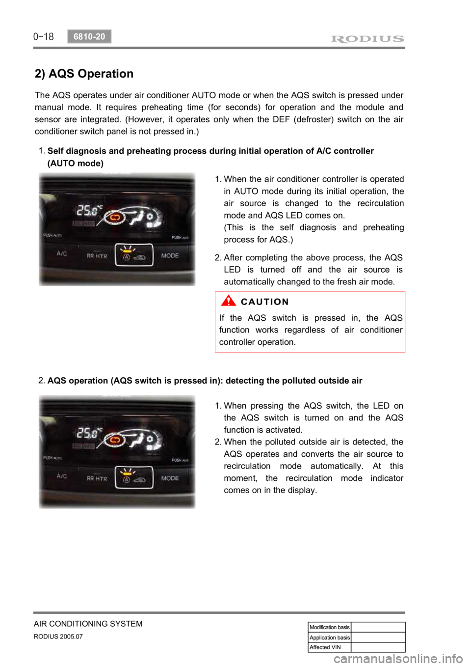
2) AQS Operation
The AQS operates under air conditioner AUTO mode or when the AQS switch is pressed under
manual mode. It requires preheating time (for seconds) for operation and the module and
sensor are integrated. (However, it operates only when the DEF (defroster) switch on the ai
r
conditioner switch panel is not pressed in.)
Self diagnosis and preheating process during initial operation of A/C controller
(AUTO mode)
1.
AQS operation (AQS switch is pressed in): detecting the polluted outside air
2.
When the air conditioner controller is operated
in AUTO mode during its initial operation, the
air source is changed to the recirculation
mode and AQS LED comes on.
(This is the self diagnosis and preheating
process for AQS.)
1.
After completing the above process, the
AQS
LED is turned off and the air source is
automatically changed to the fresh air mode.
2.
If the AQS switch is pressed in, the AQS
function works regardless of air conditioner
controller operation.
When pressing the AQS switch, the LED on
the AQS switch is turned on and the
AQS
function is activated.
When the polluted outside air is detected, the
AQS operates and converts the air source to
recirculation mode automatically. At this
moment, the recirculation mode indicato
r
comes on in the display.
1.
2.
Page 444 of 502

0-7
AIR BAG SYSTEM
RODIUS 2005.07
8810-01
4) Inflator
The inflator is a type of the direct gas generated device.
The inflator with initial low pressure provides negative restraint effect regarding passengers
moving and time.
On the contrary, the inflator with initial high pressure allows other components of the airbag
to make a excessive impact resulting in any personal injury.
Thus, the inflator output must be optimized according to the characteristic of the vehicle and
passenger moving.
The discharge gas has no toxicity or inflammability and also it is the important parameter to
control the high temperature for gas firing. ·
·
·
5) SDM (Sensing and Diagnostic Module)
The airbag system consists of the module section (driver, passenger and side), seat belt
section and SDM.
The SDM has no user-serviceable parts and monitors the system components continuously.
The SDM also records any faults which are discovered.
The SDM allows the fault codes to be retrieved with a scan tool and illuminates a warning
lamp that alerts the driver to any faults. 1.
2.
3.
The SDM located on floor beneath the floor console assembly. The SDM performs the
following functions:
Impact decision processor function.
Determine the airbag deployment through the impact signal of the accelerometer sensor and
the safety sensor. ·
·
Malfunction detection and recording any faults that are detected.
Monitor the supplemental restrain system electrical components and set a diagnostic trouble
code when malfunction is detected.
Display airbag fault codes Display airbag fault codes and system status information when
connected to a scan tool.
Self-diagnosis function Illuminate the AIRBAG indicator to alert the driver to any fault.
Power supply function Provide a reserve power source to deploy the airbags and
pretensioners if an accident has disabled the normal power source. ·
·
·
·