air condition SSANGYONG RODIUS 2005 Owner's Manual
[x] Cancel search | Manufacturer: SSANGYONG, Model Year: 2005, Model line: RODIUS, Model: SSANGYONG RODIUS 2005Pages: 502, PDF Size: 70.43 MB
Page 427 of 502

0-18
RODIUS 2005.07
6810-20
AIR CONDITIONING SYSTEM
2) AQS Operation
The AQS operates under air conditioner AUTO mode or when the AQS switch is pressed under
manual mode. It requires preheating time (for seconds) for operation and the module and
sensor are integrated. (However, it operates only when the DEF (defroster) switch on the ai
r
conditioner switch panel is not pressed in.)
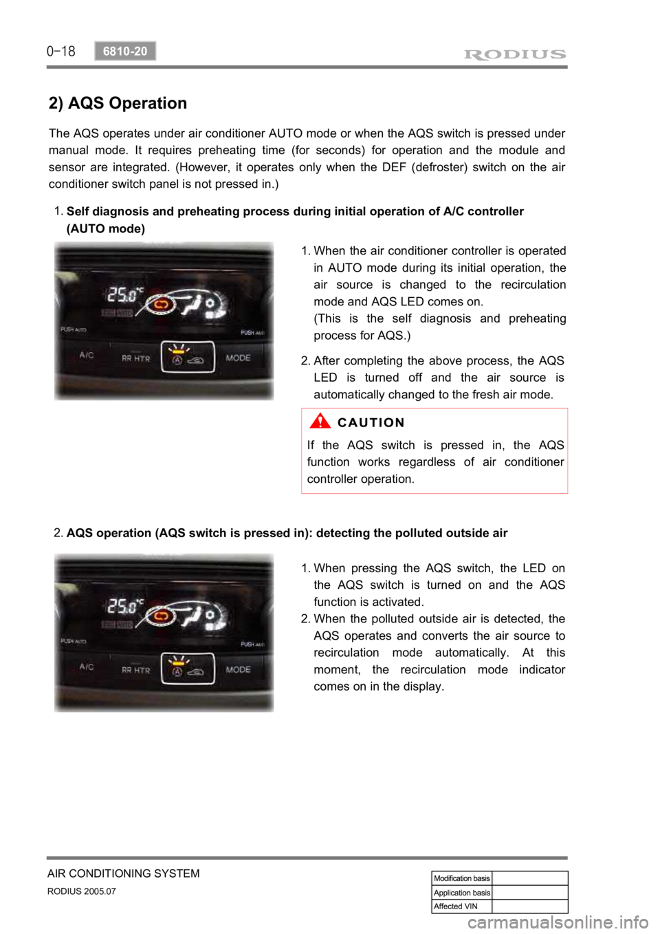
Self diagnosis and preheating process during initial operation of A/C controller
(AUTO mode)
1.
AQS operation (AQS switch is pressed in): detecting the polluted outside air
2.
When the air conditioner controller is operated
in AUTO mode during its initial operation, the
air source is changed to the recirculation
mode and AQS LED comes on.
(This is the self diagnosis and preheating
process for AQS.)
1.
After completing the above process, the
AQS
LED is turned off and the air source is
automatically changed to the fresh air mode.
2.
If the AQS switch is pressed in, the AQS
function works regardless of air conditioner
controller operation.
When pressing the AQS switch, the LED on
the AQS switch is turned on and the
AQS
function is activated.
When the polluted outside air is detected, the
AQS operates and converts the air source to
recirculation mode automatically. At this
moment, the recirculation mode indicato
r
comes on in the display.
1.
2.
Page 428 of 502

0-19
AIR CONDITIONING SYSTEM
RODIUS 2005.07
6810-20
When driving out of polluted area 3.
If the polluted air is disappeared, the air
source is automatically changed to the fresh
air mode and AQS LED stays on.
The air source is not changed when pressing
the AQS and air source selection switch in
“AUTO” mode. To change the air source to
recirculation mode in AUTO mode, get into
Manual mode first, then press the air source
selection switch. 1.
2.
Page 429 of 502
![SSANGYONG RODIUS 2005 Owners Manual 0-20
RODIUS 2005.07
6810-20
AIR CONDITIONING SYSTEM
3) AQS Operation Circuit
1. Ambient temperature switch
2. Sensor ground
3. AQS signal (Output)
4. Ground
5. IGN 2
[AQS sensor] ▶
Measure the volt SSANGYONG RODIUS 2005 Owners Manual 0-20
RODIUS 2005.07
6810-20
AIR CONDITIONING SYSTEM
3) AQS Operation Circuit
1. Ambient temperature switch
2. Sensor ground
3. AQS signal (Output)
4. Ground
5. IGN 2
[AQS sensor] ▶
Measure the volt](/img/67/57522/w960_57522-428.png)
0-20
RODIUS 2005.07
6810-20
AIR CONDITIONING SYSTEM
3) AQS Operation Circuit
1. Ambient temperature switch
2. Sensor ground
3. AQS signal (Output)
4. Ground
5. IGN 2
[AQS sensor] ▶
Measure the voltage value of AQS. (between connector terminal No. 3 and 4.)
If the measured voltage is out of 0.1 to 4.8 V, replace the AQS.
If the measured voltage is out of the specified range, replace the AQS. If it is within the
specified range, check as below.
Turn the ignition key to “ON” position.
Measure the voltage between terminal B9 and B15 on the air conditioner controller.
If the voltage value cannot be measured, check the circuit for open. If the measured value is
within the specified range, replace the FATC controller. 1.
2.
3.
4.
5.
6.
Remove the sensor and measure the resistance between terminal No. 5 and 6 on the senso
r
connector. (standard: approx. 25°C, 2.2 kΩ) In addition, if the resistance is extremely
high or low, replace the sensor.
If the measured value is out of the specified range, replace the ambient temperature sensor.
If the measured value is within the specified range, check as below.
Turn the ignition switch to ON position and measure the voltage to ambient temperature
sensor from the FATC controller connector. (standard: approx. 2 V at 25°C)
If the voltage value cannot be measured, check the circuit for open. If the measured value is
within the specified range, replace the FATC controller. 1.
2.
3.
4.[Ambient temperature sensor] ▶
Page 430 of 502

0-21
AIR CONDITIONING SYSTEM
RODIUS 2005.07
6810-20
6. AIR CONDITIONER MODULE SENSORS AND ACTUATORS
1) Duct Temperature Sensor
The duct temperature sensor is installed on the top of heater unit. It detects the inside
temperature of duct and transmits the voltage value that is changed according to resistance
value (NTC) to FATC controller.
(1) Inspection
If the duct temperature sensor defect code (DTC 3) is set, check as below.
▶
Remove the duct temperature sensor and measure the resistance between terminals on the
sensor connector. (standard: approx. 25°C, 2.2 kΩ) In addition, if the resistance is
extremely high or, replace the sensor.
If the measured value is out of the specified range, replace the duct temperature sensor. I
f
the measured value is within the specified range, check as below.
Turn the ignition switch to ON position and measure the voltage to duct temperature senso
r
from the FATC controller connector.
(standard: approx. 2 V at 25°C)
If the voltage value cannot be measured, check the circuit for open. If the measured value is
within the specified range, replace the FATC controller.
1.
2.
3.
4.
Page 431 of 502

0-22
RODIUS 2005.07
6810-20
AIR CONDITIONING SYSTEM
2) Power Transistor
The power transistor controls the fan speed. It controls the blower motor operating speed
without stages by changing the current value to the base of power transistor when receiving the
fan control signal from FATC.
Front air conditioner power transistor
Rear air conditioner power transistor
(1) Inspection
If the power transistor defect code (DTC 6) is appeared, check as below.
▶
Turn the ignition switch to ON position.
Measure the voltage between terminals while changing the fan speed from stage 1 to stage
6
The specified voltage value in each stage:
1.
2.
3.
If the voltage is out of specified value, check the circuit for open. If the circuit is in normal
condition, replace the power transistor.
4.
Page 432 of 502

0-23
AIR CONDITIONING SYSTEM
RODIUS 2005.07
6810-20
3) Mode Door Actuator
The mode door actuator is an actuator that closes, opens and adjusts the mode door for VENT,
FLOOR and DEF mode to change the air flow directions according to FATC controller. Unde
r
the FATC controller AUTO mode, it stays on DEF mode until the engine coolant temperature
reaches at normal operating level and the mode is changed as below when the MODE switch is
pressed.
Page 433 of 502

0-24
RODIUS 2005.07
6810-20
AIR CONDITIONING SYSTEM
(1) Inspection
If the intake door mode on FATC is different from the actual intake door mode,
check as below. ▶
Turn the ignition switch to ON position.
Measure the voltage between each terminal (P1 through P5)and positive (+) terminal in
respective mode.
(If the voltage is changed from 0 V to 12 V after selecting the mode, it is normal.)
If the voltage value is out of the specified value, check the related circuits for open.
If the circuits are in normal condition, replace the FATC.
If the voltage is within the specified value, replace the mode door actuator assembly.
Connect the positive (+) and negative (-) cables of temporary power supply to the doo
r
mode actuator. And, connect the negative cable to each terminal (P1 through P5) to check
its operation.
(If it operates as shown in above figure, it is normal.) 1.
2.
3.
4.
5.
6.
Circuit diagramTerminal arrangement
Page 434 of 502

0-25
AIR CONDITIONING SYSTEM
RODIUS 2005.07
6810-20
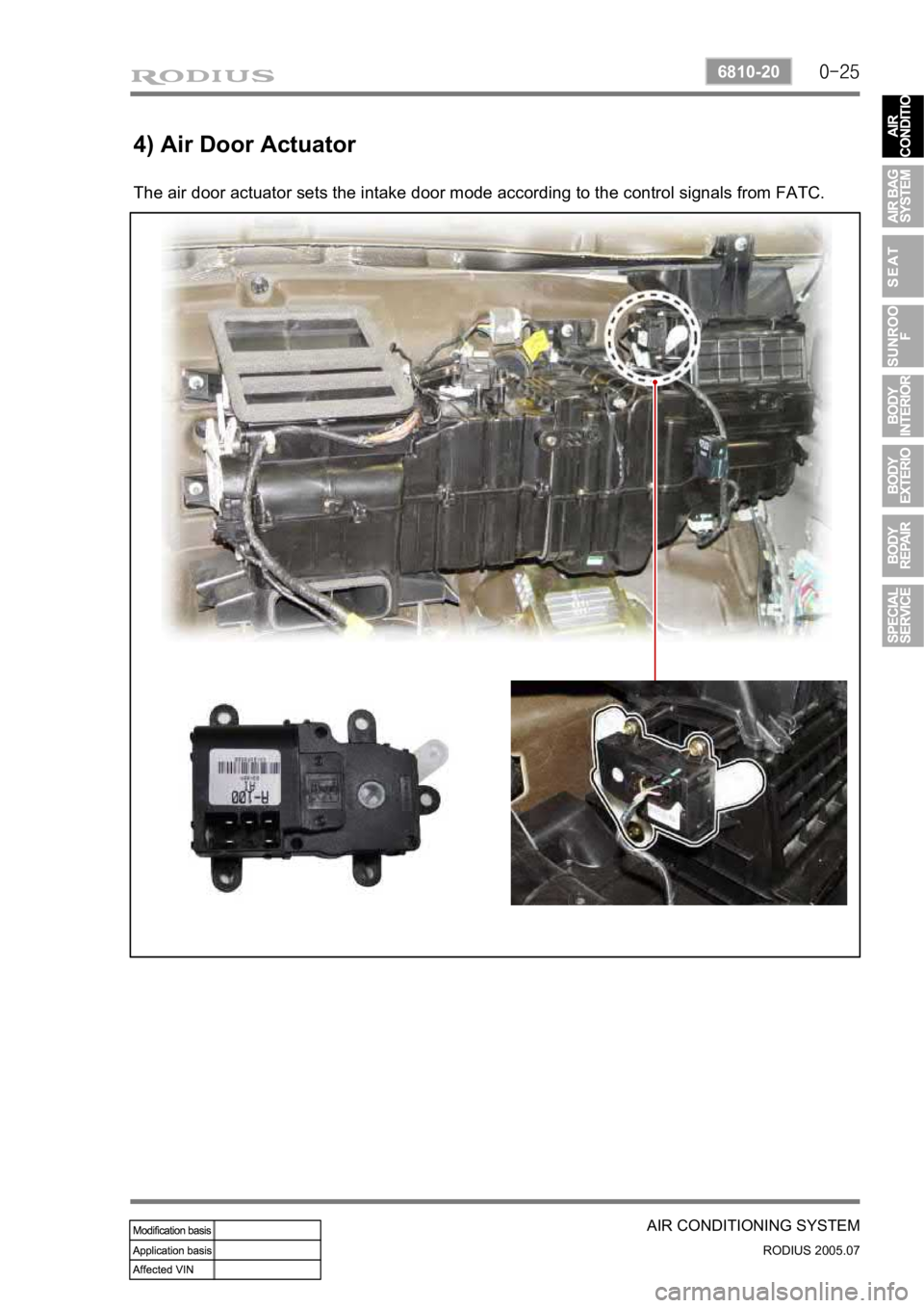
4) Air Door Actuator
The air door actuator sets the intake door mode according to the control signals from FATC.
Page 435 of 502

0-26
RODIUS 2005.07
6810-20
AIR CONDITIONING SYSTEM
(1) Inspection
Terminal arrangementCircuit diagram
If the intake door mode on FATC is different from the actual intake door mode, check
as below. ▶
Turn the ignition switch to ON position.
Measure the voltage between terminal P1 and P2 (approx. 12 V) and terminal a and b
(approx. 5V).
If the voltage value is out of the specified value, check the related circuits for open.
If the circuits are in normal condition, replace the air door actuator assembly.
If the voltage is within the specified value, replace the mode door actuator assembly.
Connect the positive (+) and negative (-) cables of temporary power supply to the air doo
r
actuator. And, connect the cable to each terminal (P1 and P2) in turn to check the moto
r
operation and terminal output. 1.
2.
3.
4.
5.
6.
Air source Mode Bc resistance
Fresh air P1 (-), P2 (+)below 300 Ω
Recirculation P1 (+), P2 (-)over 2.4 kΩ
Page 436 of 502

0-27
AIR CONDITIONING SYSTEM
RODIUS 2005.07
6810-20
5) Air Mix Door Actuator
The air mix door actuator controls the discharging air temperature properly by closing/opening
the damper according to the control signals from FATC.