SSANGYONG RODIUS 2005 Owner's Manual
RODIUS 2005
SSANGYONG
SSANGYONG
https://www.carmanualsonline.info/img/67/57522/w960_57522-0.png
SSANGYONG RODIUS 2005 Owner's Manual
Page 214 of 502

0-7
TORQUE ON DEMAND
RODIUS 2005.07
3240-01
2) Transfer Case
(1) Planetary gear set
Planetary Gear set consists of sun gear, ring gear and carrier. It is engaged with the gear in
“HIGH-LOW” collar to increase the driving force by reducing vehicle speed.
Sun gear is connected to input shaft and ring gear is fixed into the transfer case.
Splined rear output shaft is able to slide on the “HIGH - LOW” collar.
The inside and outside ends of “HIGH - LOW” collar have machined gear. The input
shaft transmits the power to driving wheels by engaging with sun gear and carrier gear.
If the 4WD switch is at “4WD HIGH”, the TOD control unit operates the shift motor to
engage “HIGH - LOW” collar directly with input shaft for transmitting the driving force
to front and rear propeller shafts.
When a driver selects “4WD LOW”, the TOD control unit controls the electro-magnetic
clutch and operates the shift motor to engage “HIGH - LOW” collar with carrier.
The power from transmission is increased up to 2.48:1 by reduction ratio from planetary
gear, and then is sent to front and rear propeller shafts. null
(2) Ball type slant cam and clutch
disc pack
If the speed sensors installed on front and
rear propeller shafts detect the slips at front
and rear wheels, and these slips exceed
the specified range, TOD control unit
controls electromagnetic clutch to transmit
driving force to front wheels.
At this time, ball slant cam is moved to
compress multi-disc located in clutch disc to
transmit driving force to front wheels.
Page 215 of 502
0-8
RODIUS 2005.07
3240-01
TORQUE ON DEMAND
(3) Electro Magnetic Clutch (EMC)
EMC consists of coil and housing. TOD control unit controls EMC by controlling duty cycle
according to the road and driving conditions. These controls use the continuity time and amount
of electric current to determine the torque to be transmitted to front wheels.
Basic controls in EMC ▶
Page 216 of 502
0-9
TORQUE ON DEMAND
RODIUS 2005.07
3240-01
3) Signal Flow
Page 217 of 502
0-10
RODIUS 2005.07
3240-01
TORQUE ON DEMAND
4) Power Flow
(1) 4H Mode (4WD Drive - High Speed)
Page 218 of 502
0-11
TORQUE ON DEMAND
RODIUS 2005.07
3240-01
(2) 4H Mode (4WD Drive - Low Speed)
Page 219 of 502
0-12
RODIUS 2005.07
3240-01
TORQUE ON DEMAND
3. OPERATION
1) System Layout
Page 220 of 502
0-13
TORQUE ON DEMAND
RODIUS 2005.07
3240-01
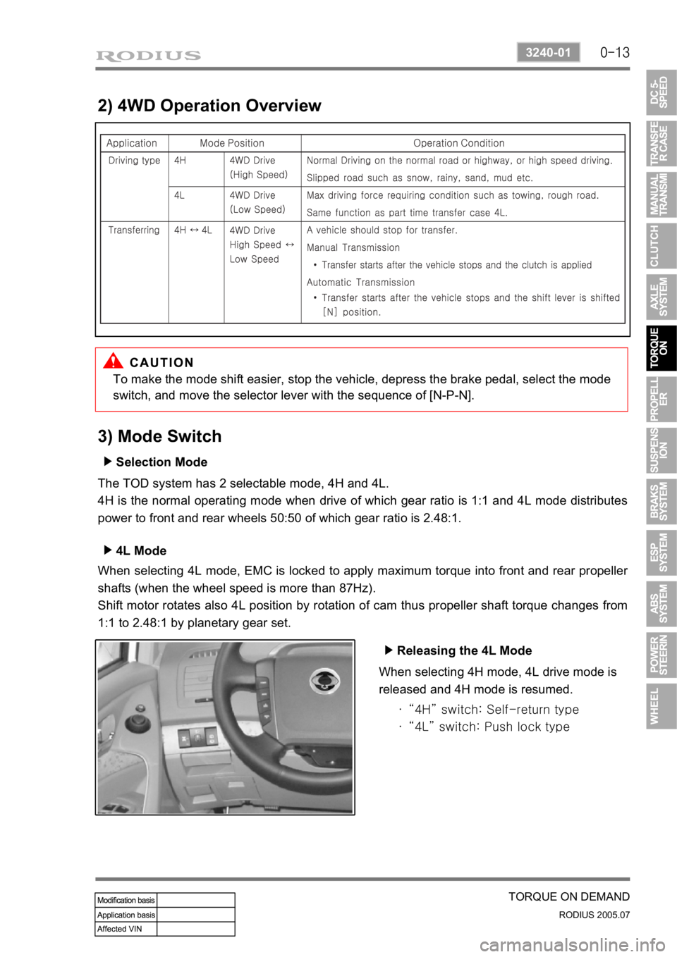
2) 4WD Operation Overview
To make the mode shift easier, stop the vehicle, depress the brake pedal, select the mode
switch, and move the selector lever with the sequence of [N-P-N].
3) Mode Switch
Selection Mode ▶
The TOD system has 2 selectable mode, 4H and 4L.
4H is the normal operating mode when drive of which gear ratio is 1:1 and 4L mode distributes
power to front and rear wheels 50:50 of which gear ratio is 2.48:1.
4L Mode ▶
When selecting 4L mode, EMC is locked to apply maximum torque into front and rear propelle
r
shafts (when the wheel speed is more than 87Hz).
Shift motor rotates also 4L position by rotation of cam thus propeller shaft torque changes from
1:1 to 2.48:1 by planetary gear set.
Releasing the 4L Mode ▶
When selecting 4H mode, 4L drive mode is
released and 4H mode is resumed.
“4H” switch: Self-return type
“4L” switch: Push lock type ·
·
Page 221 of 502
0-14
RODIUS 2005.07
3240-01
TORQUE ON DEMAND
4. CIRCUIT DIAGRAM
Page 262 of 502

0-10
RODIUS 2005.07
4892-01
ABS SYSTEM
3. ON-VEHICLE SERVICE
(1) Electronic system service precautions
Take care to avoid electronic brake control module (HECU) circuit overloading. In testing for
opens or shorts, do not ground or apply voltage to any circuit unless instructed to do so by the
diagnostic procedure. Test circuits only with a high-impedance multi-meter. Never remove o
r
apply power to any control module with the ignition switch in the ON position. Always turn the
ignition to the OFF position before removing or connecting battery cables, fuses or connectors.
(2) General service precautions
Disconnect the HECU connector before performing any vehicle welding work using an electric
arc welder. Do not attempt to disassemble any component designated as nonserviceable. The
hydraulic modulator and the HECU can be seperated. (There is however no access to repai
r
the each components.)
(3) Bleeding system
Replacement modulators are shipped already filled and bled. In normal procedures requiring
removal of the modulator, such as to replace the HECU, air will not enter the modulator, and
normal bleeding will be all that is needed.
If air enters the hydraulic modulator, or if an unfilled modulator is installed, use the brake
bleeding program in the scan tool to bleed the modulator. Manual bleeding of the hydraulic
modulator is not possible.
1) Service Precautions
Brake Fluid may irritate eyes and skin. In case of contact, take the following actions:
Eye contact - rinse thoroughly with water.
Skin contact - wash with soap and water.
Ingestion - consult a physician immediately. -
-
-
To help avoid personal injury due to poor braking. DO NOT Tap into the vehicle’s
brake system to operate a trailer brake system.
When fasteners are removed, always reinstall them at the same location from which they
were removed. If a fastener needs to be replaced, use the correct part number fastener
for is not available, a fastener of equal size and strength (or stronger) may be used.
Fasteners that are not reused, and those requiring thread-locking compound will be
called out. The correct torque values must be used when installing fasteners that require
them. If the above procedures are not followed, parts or system damage could result.
Page 276 of 502
0-4
RODIUS 2005.07
4610-00
POWER STEERING SYSTEM
2. TIGHTENING TORQUE
3. SPECIAL TOOLS AND EQUIPMENT


