heater SSANGYONG RODIUS 2005 Service Manual
[x] Cancel search | Manufacturer: SSANGYONG, Model Year: 2005, Model line: RODIUS, Model: SSANGYONG RODIUS 2005Pages: 502, PDF Size: 70.43 MB
Page 47 of 502

CIRCUIT
1461-01/2820-01/1491-01/1491-01/8210-01/3670-01/3670-03/3410-01/4891-01/4920-01/4480-01/8810-01/8010-01/8610-04/8610-11/7421-60/8510-52/8610-17/8510
-
20
/
8710-03/8510-03/8710-03/8510-12/8610-09/7630-02/7340-03/8310-01/8510-00/8320-01/8510-26/8510-24/4810-10/8610-01/7770-07/8910-01/8730-01/6810-21/6910
-
01
/
6810-30/6810-30
CIRCUIT
ENGINE
8910-01 AUDIO (MULTI VISION)................
8910-01 AUDIO..........................................
8730-01 PARKING AID CIRCUIT................
6810-21 PTC HEATER (POSITIVE
TEMPERATURE
COEFFICIENT).............................
6910-01 FFH (FUEL FIRED HEATER).........
6810-30 FATC (FULL AUTO TEMP.
CONTROL) CIRCUIT....................
6810-30 AIR-CON (MANUAL).....................
CHASSIS3670-01 TCU (5-SPEED)............................
3670-03 TOD.............................................
3410-01 TCCU...........................................
4891-01 ABS/ESP......................................
4920-01 EPB..............................................
4480-01 EAS..............................................ELECTRIC
8610-17 DEFFOGER (FRT GLASS, RR
GLASS, OUTSIDE MIRROR)........
8510-20 FRT SEAT WARMER...................
8510-20 AUTO LIGHT CORTROL CIRC.....
8710-03 STICS..........................................
8510-03 POWER WINDOW CIRCUIT.........
8710-03 CENTRAL DOOR LOCKING
CIRCUIT.......................................
8510-12 RR WIPER & WASHER
CIRCUIT.......................................
8610-09 HORN...........................................
7630-02 CIGAR LIGHTER, POWER
OUTLET......................................
7340-03 SUN ROOF CIRCUIT....................
8310-01 HEAD LAMP & DRL (DAY TIME
RUNNING LIGHT) UNIT
CIRCUIT.......................................
8510-00 HEAD LAMP LEVELING DEVICE
CIRCUIT.......................................
8320-01 TAIL LAMP CIRCUIT...................
8510-26 TURN SIGNAL & HAZARD LAMP
CIRCUIT.......................................
8510-24 FOG LAMP CIRCUIT....................
4810-10 STOP & BACK-UP LAMP
CIRCUIT.......................................
8610-01 INTERIOR LAMP(ROOM,
G/HENDLE, DOOR COURTESY)
CIRCUIT......................................
7770-07 AUTO DIMMING ROOM MIRROR
CIRCUIT....................................... 8810-01 AIR-BAG.......................................
8010-01 CLUSTER.....................................
8610-04 MULTI METER.............................
8610-11 RAIN SENSING WIPER
CIRCUIT.......................................
7421-60 DRIVER POWER SEAT
CIRCUIT.......................................
8510-52 ELECTRIC OUTSIDE MIRROR &
FOLDING CIRCUIT.......................49
52
53
54
55
56
59
12
14
15
16
18
19
20
21
24
25
26
2728
29
30
31
35
36
37
38
39
40
41
42
43
44
45
46
47
48 1461-01 STARTING & CHARGING............
2820-01 PREHEATING UNIT CIRCUIT
(XDi))............................................
1491-01 ECU (ENGINE CONTROL UNIT -
XDi)..............................................
1491-01 ECU (GSL G32)............................
8210-01 DIAGNOSIS CIRCUIT...................3
4
5
8
11
Page 100 of 502

0-54RODIUS 2005.07
6810-21
CIRCUIT
2) CONNECTOR IDENTIFICATION SYMBOL & PIN NUMBER POSITION
1) CONNECTOR INFORMATION
6810-21
PTC HEATER
(POSITIVE TEMPERATURE COEFFICIENT)
Page 101 of 502

0-55
CIRCUIT
RODIUS 2005.07
6910-01
6910-01
FFH (FUEL FIRED HEATER)
2) CONNECTOR IDENTIFICATION SYMBOL & PIN NUMBER POSITION
1) CONNECTOR INFORMATION
Page 123 of 502

07-7
ENGINE COOLING SYSTEM
RODIUS 2005.07
2110-01
3) COOLANT RESERVOIR
The coolant reservoir is a transparent plastic reservoir, similar to the windshield washer
reservoir.
The coolant reservoir is connected to the radiator by a hose and to the engine cooling system
by another hose. As the vehicle is driven, the engine coolant heats and expands. The portion o
f
the engine coolant displaced by this expansion flows from the radiator and the engine into the
coolant reservoir. The air trapped in the radiator and the engine is degassed into the coolant
reservoir.
When the engine stops, the engine coolant cools and contracts. The displaced engine coolant
is then drawn back into the radiator and the engine. This keeps the radiator filled with the
coolant to the desired level at all times and increases the cooling efficiency.
Maintain the coolant level between the MIN and MAX marks on the coolant reservoir when the
system is cold.
4) THERMOSTAT
A wax pellet-type thermostat controls the flow of the engine coolant through the engine cooling
system. The thermostat is mounted in the thermostat housing to the front of the cylinder head.
The thermostat stops the flow of the engine coolant from the engine to the radiator to provide
faster warm-up, and to regulate the coolant temperature. The thermostat remains closed while
the engine coolant is cold, preventing circulation of the engine coolant through the radiator.
At
this point, the engine coolant is allowed to circulate only throughout the heater core to warm it
quickly and evenly.
As the engine warms, the thermostat opens. This allows the engine coolant to flow through the
radiator where the heat is dissipated. This opening and closing of the thermostat permits
enough engine coolant to enter the radiator to keep the engine within proper engine
temperature operating limits.
The wax pellet in the thermostat is hermetically sealed in a metal case. The wax element of the
thermostat expands when it is heated and contracts when it is cooled.
As the vehicle is driven and the engine warms, the engine coolant temperature increases.
When the engine coolant reaches a specified temperature, the wax pellet element in the
thermostat expands and exerts pressure against the metal case, forcing the valve open. This
allows the engine coolant to flow through the engine cooling system and cool the engine.
As the wax pellet cools, the contraction allows a spring to close the valve.
The thermostat begins to open at 82°C (180°F) and is fully open at 95°C (203°F). The
thermostat closes at 80°C (176°F).
Page 340 of 502

0-27
STICS
RODIUS 2005.07
8710-01
This vehicle has the windshield heated glass and the tailgate and outside rearview mirror
heated glass. The heater relay in the ICM box controls the tailgate and outside rearview mirro
r
heated glass and its fuse (15A) is located in the engine compartment fuse box.
Defogger switch
Page 419 of 502

0-10
RODIUS 2005.07
6810-20
AIR CONDITIONING SYSTEM
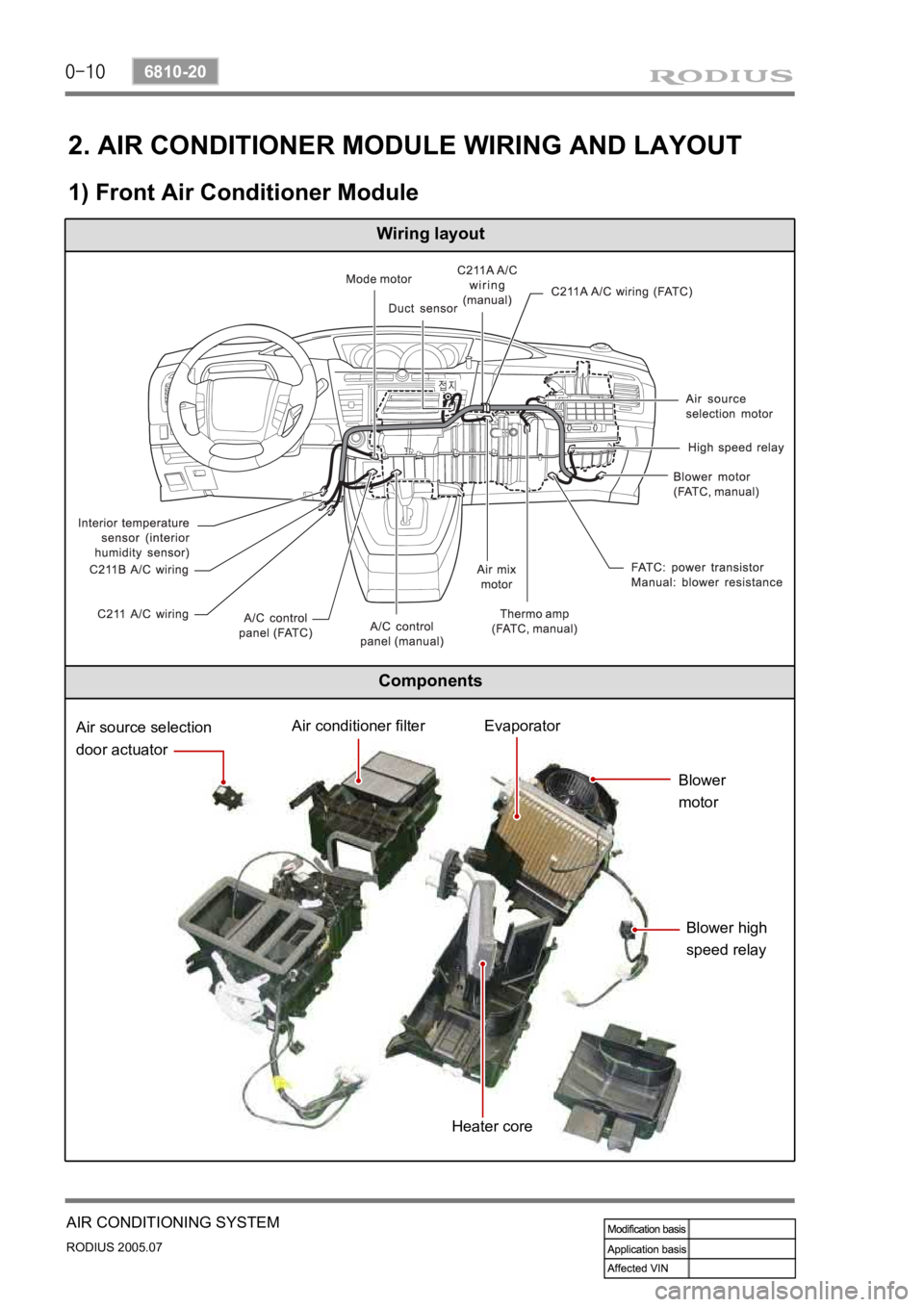
2. AIR CONDITIONER MODULE WIRING AND LAYOUT
1) Front Air Conditioner Module
Wiring layout
Components
Air source selection
door actuatorAir conditioner filterEvaporator
Blower
motor
Blower high
speed relay
Heater core
Page 420 of 502

0-11
AIR CONDITIONING SYSTEM
RODIUS 2005.07
6810-20
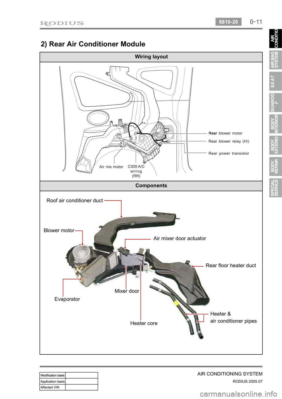
2) Rear Air Conditioner Module
Wiring layout
Components
Roof air conditioner duct
Blower motor
EvaporatorAir mixer door actuator
Rear floor heater duct
Mixer door
Heater coreHeater &
air conditioner pipes
Page 421 of 502

0-12
RODIUS 2005.07
6810-20
AIR CONDITIONING SYSTEM
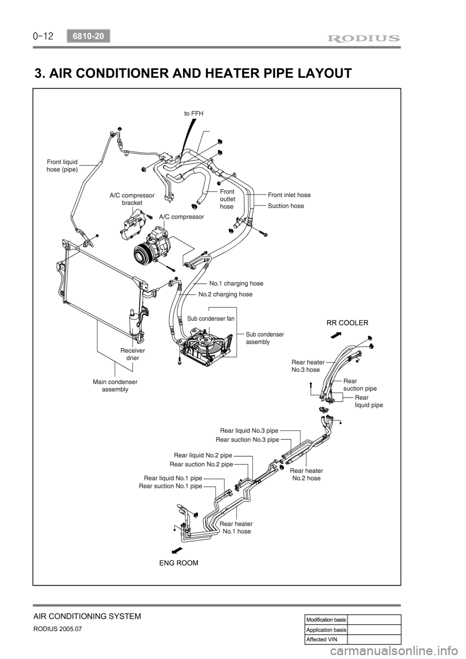
3. AIR CONDITIONER AND HEATER PIPE LAYOUT
Page 430 of 502

0-21
AIR CONDITIONING SYSTEM
RODIUS 2005.07
6810-20
6. AIR CONDITIONER MODULE SENSORS AND ACTUATORS
1) Duct Temperature Sensor
The duct temperature sensor is installed on the top of heater unit. It detects the inside
temperature of duct and transmits the voltage value that is changed according to resistance
value (NTC) to FATC controller.
(1) Inspection
If the duct temperature sensor defect code (DTC 3) is set, check as below.
▶
Remove the duct temperature sensor and measure the resistance between terminals on the
sensor connector. (standard: approx. 25°C, 2.2 kΩ) In addition, if the resistance is
extremely high or, replace the sensor.
If the measured value is out of the specified range, replace the duct temperature sensor. I
f
the measured value is within the specified range, check as below.
Turn the ignition switch to ON position and measure the voltage to duct temperature senso
r
from the FATC controller connector.
(standard: approx. 2 V at 25°C)
If the voltage value cannot be measured, check the circuit for open. If the measured value is
within the specified range, replace the FATC controller.
1.
2.
3.
4.