ignition SSANGYONG RODIUS 2005 Service Manual
[x] Cancel search | Manufacturer: SSANGYONG, Model Year: 2005, Model line: RODIUS, Model: SSANGYONG RODIUS 2005Pages: 502, PDF Size: 70.43 MB
Page 4 of 502
0-4RODIUS 2005.07
0000-00
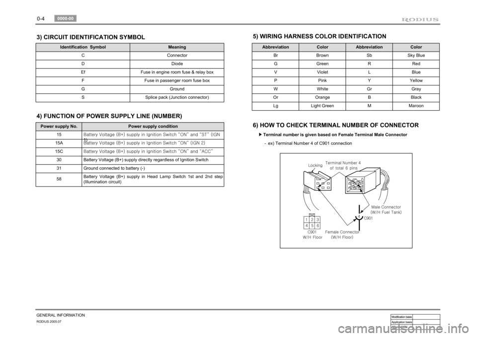
GENERAL INFORMATION3) CIRCUIT IDENTIFICATION SYMBOL
Identification Symbol Meaning
C Connector
D Diode
Ef Fuse in engine room fuse & relay box
F Fuse in passenger room fuse box
G Ground
S Splice pack (Junction connector)
5) WIRING HARNESS COLOR IDENTIFICATION
Abbreviation Color Abbreviation Color
Br Brown Sb Sky Blue
G Green R Red
V Violet L Blue
P Pink Y Yellow
W White Gr Gray
Or Orange B Black
Lg Light Green M Maroon
6) HOW TO CHECK TERMINAL NUMBER OF CONNECTOR
Terminal number is given based on Female Terminal Male Connector ▶
ex) Terminal Number 4 of C901 connection -
Power supply No. Power supply condition
15<00690088009b009b008c009900a00047007d00960093009b0088008e008c0047004f0069005200500047009a009c00970097009300a000470090009500470070008e00950090009b0090009600950047007a009e0090009b008a008f004702c80076007502
c9004700880095008b004702c8007a007b02c90047004f0070>GN
1)
15A<00690088009b009b008c009900a00047007d00960093009b0088008e008c0047004f0069005200500047009a009c00970097009300a000470090009500470070008e00950090009b0090009600950047007a009e0090009b008a008f004702c80076007502
c90047004f0070006e0075004700590050>
15C<00690088009b009b008c009900a00047007d00960093009b0088008e008c0047004f0069005200500047009a009c00970097009300a000470090009500470070008e00950090009b0090009600950047007a009e0090009b008a008f004702c80076007502
c9004700880095008b004702c80068006a006a02c9>
30 Battery Voltage (B+) supply directly regardless of Ignition Switch
31 Ground connected to battery (-)
58Battery Voltage (B+) supply in Head Lamp Switch 1st and 2nd step
(Illumination circuit)4) FUNCTION OF POWER SUPPLY LINE (NUMBER)
Page 112 of 502
01-5
ENGINE GENERAL
RODIUS 2005.07
0000-00
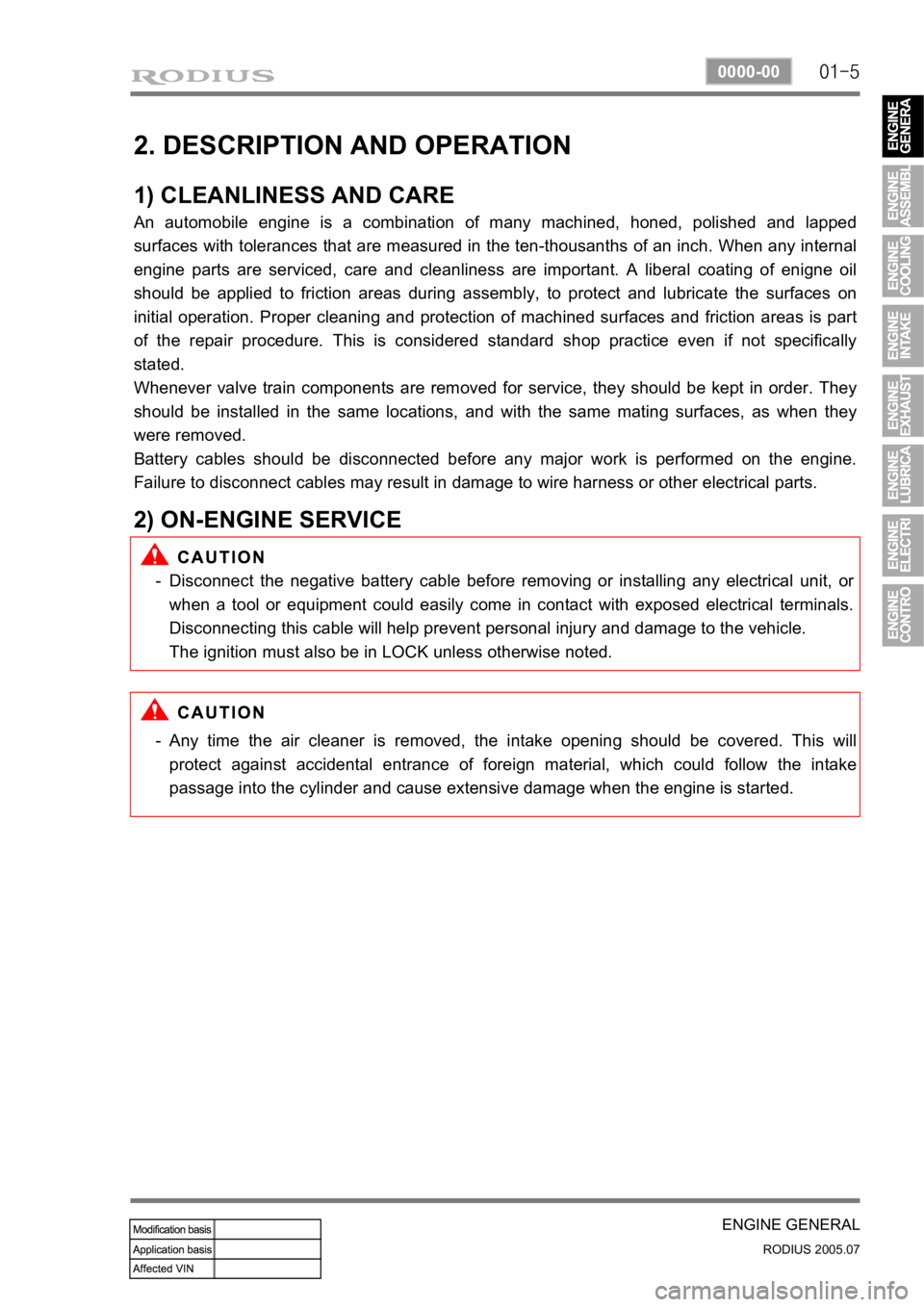
2. DESCRIPTION AND OPERATION
1) CLEANLINESS AND CARE
An automobile engine is a combination of many machined, honed, polished and lapped
surfaces with tolerances that are measured in the ten-thousanths of an inch. When any internal
engine parts are serviced, care and cleanliness are important. A liberal coating of enigne oil
should be applied to friction areas during assembly, to protect and lubricate the surfaces on
initial operation. Proper cleaning and protection of machined surfaces and friction areas is part
of the repair procedure. This is considered standard shop practice even if not specifically
stated.
Whenever valve train components are removed for service, they should be kept in order. They
should be installed in the same locations, and with the same mating surfaces, as when they
were removed.
Battery cables should be disconnected before any major work is performed on the engine.
Failure to disconnect cables may result in damage to wire harness or other electrical parts.
2) ON-ENGINE SERVICE
Disconnect the negative battery cable before removing or installing any electrical unit, or
when a tool or equipment could easily come in contact with exposed electrical terminals.
Disconnecting this cable will help prevent personal injury and damage to the vehicle.
The ignition must also be in LOCK unless otherwise noted. -
Any time the air cleaner is removed, the intake opening should be covered. This will
protect against accidental entrance of foreign material, which could follow the intake
passage into the cylinder and cause extensive damage when the engine is started. -
Page 117 of 502
02-6
RODIUS 2005.07
1113-01
ENGINE ASSEMBLY
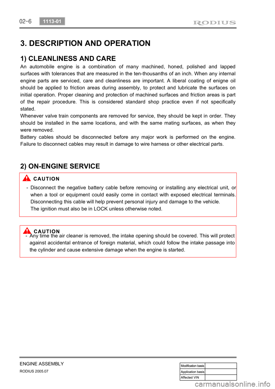
3. DESCRIPTION AND OPERATION
1) CLEANLINESS AND CARE
An automobile engine is a combination of many machined, honed, polished and lapped
surfaces with tolerances that are measured in the ten-thousanths of an inch. When any internal
engine parts are serviced, care and cleanliness are important. A liberal coating of enigne oil
should be applied to friction areas during assembly, to protect and lubricate the surfaces on
initial operation. Proper cleaning and protection of machined surfaces and friction areas is part
of the repair procedure. This is considered standard shop practice even if not specifically
stated.
Whenever valve train components are removed for service, they should be kept in order. They
should be installed in the same locations, and with the same mating surfaces, as when they
were removed.
Battery cables should be disconnected before any major work is performed on the engine.
Failure to disconnect cables may result in damage to wire harness or other electrical parts.
2) ON-ENGINE SERVICE
Disconnect the negative battery cable before removing or installing any electrical unit, or
when a tool or equipment could easily come in contact with exposed electrical terminals.
Disconnecting this cable will help prevent personal injury and damage to the vehicle.
The ignition must also be in LOCK unless otherwise noted. -
Any time the air cleaner is removed, the intake opening should be covered. This will protect
against accidental entrance of foreign material, which could follow the intake passage into
the cylinder and cause extensive damage when the engine is started. -
Page 146 of 502
08-8
RODIUS 2005.07
1452-01
ENGINE ELECTRIC SYSTEM
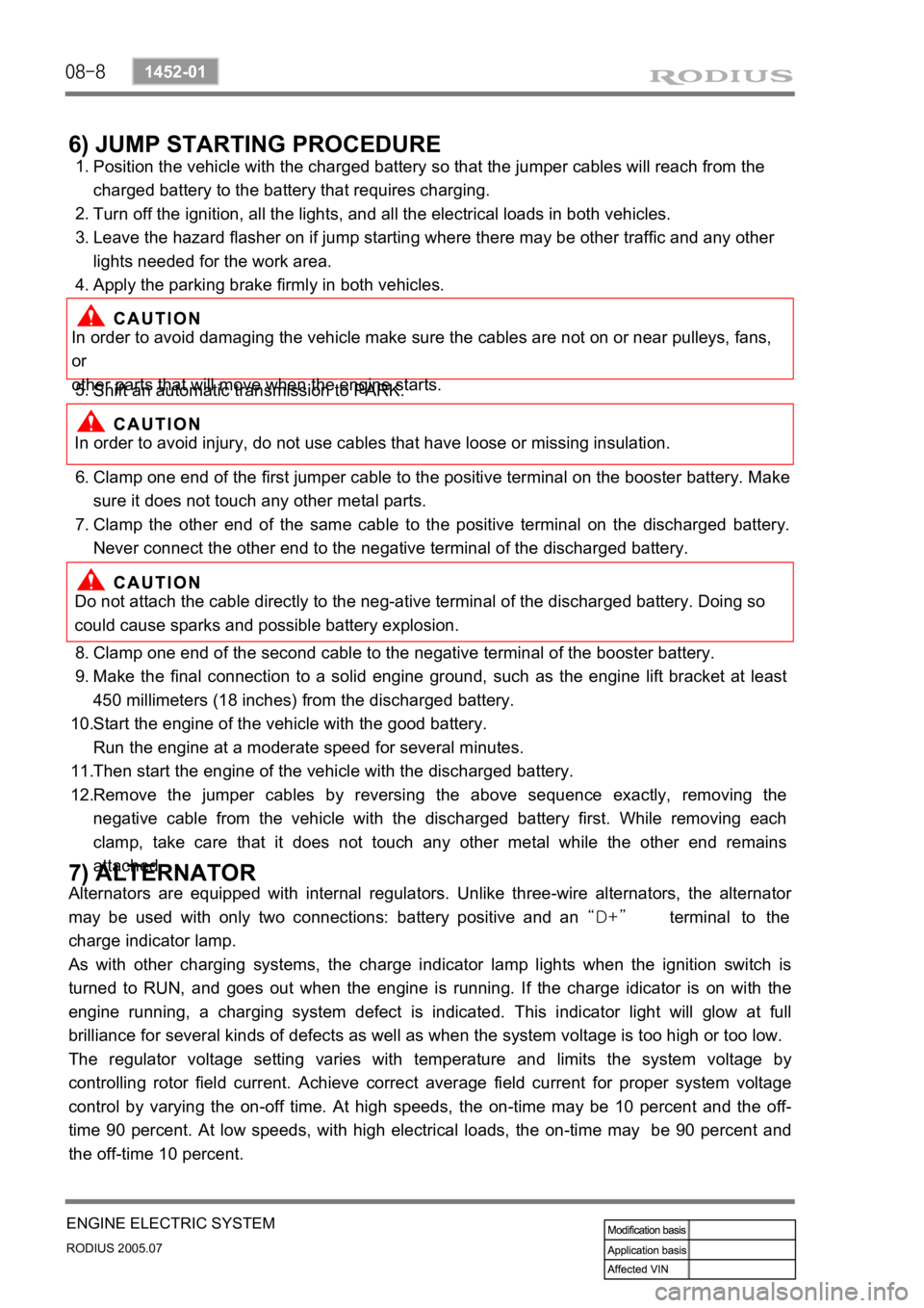
6) JUMP STARTING PROCEDURE
Position the vehicle with the charged battery so that the jumper cables will reach from the
charged battery to the battery that requires charging.
Turn off the ignition, all the lights, and all the electrical loads in both vehicles.
Leave the hazard flasher on if jump starting where there may be other traffic and any other
lights needed for the work area.
Apply the parking brake firmly in both vehicles. 1.
2.
3.
4.
In order to avoid damaging the vehicle make sure the cables are not on or near pulleys, fans,
or
other parts that will move when the engine starts.
Shift an automatic transmission to PARK. 5.
In order to avoid injury, do not use cables that have loose or missing insulation.
Clamp one end of the first jumper cable to the positive terminal on the booster battery. Make
sure it does not touch any other metal parts.
Clamp the other end of the same cable to the positive terminal on the discharged battery.
Never connect the other end to the negative terminal of the discharged battery. 6.
7.
Do not attach the cable directly to the neg-ative terminal of the discharged battery. Doing so
could cause sparks and possible battery explosion.
Clamp one end of the second cable to the negative terminal of the booster battery.
Make the final connection to a solid engine ground, such as the engine lift bracket at least
450 millimeters (18 inches) from the discharged battery.
Start the engine of the vehicle with the good battery.
Run the engine at a moderate speed for several minutes.
Then start the engine of the vehicle with the discharged battery.
Remove the jumper cables by reversing the above sequence exactly, removing the
negative cable from the vehicle with the discharged battery first. While removing each
clamp, take care that it does not touch any other metal while the other end remains
attached. 8.
9.
10.
11.
12.
7) ALTERNATOR
Alternators are equipped with internal regulators. Unlike three-wire alternators, the alternator
may be used with only two connections: battery positive and an “D+” terminal to the
charge indicator lamp.
As with other charging systems, the charge indicator lamp lights when the ignition switch is
turned to RUN, and goes out when the engine is running. If the charge idicator is on with the
engine running, a charging system defect is indicated. This indicator light will glow at full
brilliance for several kinds of defects as well as when the system voltage is too high or too low.
The regulator voltage setting varies with temperature and limits the system voltage by
controlling rotor field current. Achieve correct average field current for proper system voltage
control by varying the on-off time. At high speeds, the on-time may be 10 percent and the off-
time 90 percent. At low speeds, with high electrical loads, the on-time may be 90 percent and
the off-time 10 percent.
Page 147 of 502
08-9
ENGINE ELECTRIC SYSTEM
RODIUS 2005.07
1452-01
8) STARTER
Wound field starter motors have pole pieces, arranged around the armature, which are
energized by wound field coils.
Enclosed shift lever cranking motors have the shift lever mechanism and the solenoid plunge
r
enclosed in the drive housing, protecting them from exposure to dirt, icy conditions, and
splashes. In the basic circuit, solenoid windings are energized when the switch is closed. The
resulting plunger and shift lever movement causes the pinion to engage the engine flywheel
ring gear. The solenoid main contacts close. Cranking then takes place.
When the engine starts, pinion overrun protects the armature from excessive speed until the
switch is opened, at which time the return spring causes the pinion to disengage.
To prevent excessive overrun, the switch should be released immediately after the engine
starts.
9) STARTING SYSTEM
The engine electrical system includes the battery, the ignition, the starter, the alternator, and all
the related wiring.
Diagnostic tables will aid in troubleshooting system faults.
When a fault is traced to a particular component, refer to that component section of the service
manual.
The starting system circuit consists of the battery, the starter motor, the ignition switch, and all
the related electrical wiring. All of these components are connected electrically.
Page 154 of 502
09-8
RODIUS 2005.07
0452-01
ENGINE CONTROL SYSTEM
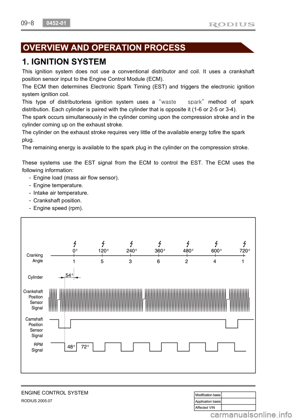
1. IGNITION SYSTEM
This ignition system does not use a conventional distributor and coil. It uses a crankshaft
position sensor input to the Engine Control Module (ECM).
The ECM then determines Electronic Spark Timing (EST) and triggers the electronic ignition
system ignition coil.
This type of distributorless ignition system uses a “waste spark” method of spark
distribution. Each cylinder is paired with the cylinder that is opposite it (1-6 or 2-5 or 3-4).
The spark occurs simultaneously in the cylinder coming upon the compression stroke and in the
cylinder coming up on the exhaust stroke.
The cylinder on the exhaust stroke requires very little of the available energy tofire the spark
plug.
The remaining energy is available to the spark plug in the cylinder on the compression stroke.
These systems use the EST signal from the ECM to control the EST. The ECM uses the
following information:
Engine load (mass air flow sensor).
Engine temperature.
Intake air temperature.
Crankshaft position.
Engine speed (rpm). -
-
-
-
-
Page 156 of 502
09-10
RODIUS 2005.07
0452-01
ENGINE CONTROL SYSTEM
1) Starting Mode
When the ignition is turned ON, the ECM turns the fuel pump relay on for 1 second.
The fuel pump then builds fuel pressure.
The ECM also checks the Engine Coolant Temperature (ECT) sensor and the Throttle Position
(TP) sensor and determines the proper air/fuel ratio for starting the engine.
This ranges from1.5 to 1 at -36°C (-33°F) coolant temperature to 14.7 to 1 at 94°C
(201°F) coolant temperature.
The ECM controls the amount of fuel delivered in the starting mode by changing how long the
fuel injector is turned on and off.
This is done by ‘‘pulsing” the fuel injectors for very short times.
<007b008f008c00470099009c0095004700940096008b008c0047008f0088009a0047009b009e00960047008a00960095008b0090009b009000960095009a0047008a008800930093008c008b004702c402c400960097008c00950047009300960096009702
c9004700880095008b004702c402c4008a00930096009a008c>d loop”.
2) Run Mode
3) Open Loop
When the engine is first started and it is above 690 rpm, the system goes into “open
loop” operation. In “open loop”, the ECM ignores the signal from the O2S and calculates
the air/fuel ratio based on inputs from the ECT sensor and the MAF sensor.
The ECM stays in “open loop” until the following conditions are met:
The O2 has a varying voltage output, showing that it is hot enough to operate properly.
<007b008f008c0047006c006a007b0047009a008c0095009a0096009900470090009a0047008800890096009d008c004700880047009a0097008c008a0090008d0090008c008b0047009b008c00940097008c00990088009b009c0099008c0047004f005900
5900550047005c00b6006a00500055>
A specific amount of time has elapsed after starting the engine. -
-
-
4) Closed Loop
The specific values for the above conditions vary with different engines and are stored in the
Electronically Erasable programmable Read-Only Memory (EEPROM).
When these conditions are met, the system goes into “closed loop” operation. In “closed
loop”, the ECM calculates the air/fuel ratio (fuel injector on-time) based on the signals
from the O2 sensors.
This allows the air/fuel ratio to stay very close to 14.7 to 1.
5) Acceleration Mode
The ECM responds to rapid changes in throttle position and airflow and provides extra fuel.
The ECM responds to changes in throttle position and airflow and reduces the amount of fuel.
When deceleration is very fast, the ECM can cut off fuel completely for short periods of time.
6) Deceleration Mode
Page 157 of 502
09-11
ENGINE CONTROL SYSTEM
RODIUS 2005.07
0452-01
No fuel is delivered by the fuel injectors when the ignition is off.
This prevents dieseling or engine run-on. Also, the fuel is not delivered if there are no reference
pulses received from the CKP sensor.
This prevents flooding.
8) Fuel Cut-Off Mode
Increasing the fuel injector pulse width.
Increasing the idle speed rpm.
Increasing the ignition dwell time. -
-
- When battery voltage is low, the ECM can compensate for a weak spark delivered by the
ignition module by using the following methods
7) Battery Voltage Correction Mode
3. EXHAUST SYSTEM
1) Catalytic Converter
The purpose of the catalytic converter is to convert the three pollutants of carbon
monoxide(CO), hydrocarbons (HC) and oxides of nitrogen (NOx) contained in the exhaust o
f
gasoline engines, into the harmless compounds of water (H2O), carbon dioxide (CO2) and
nitrogen (N2).
The catalytic converter contains a catalyst, a word coming from the Greek and which
designates the element essential for catalyst which triggers chemical reactions without itsel
f
being consumed.
These catalysts in the 3-way catalytic converter are the rare metals platinum (Pt) and rhodium
(Rh).
The catalytic converter consists essentially of three main elements.
The exhaust gases flow through the catalytic converter and, in so doing, coming into contact
with rare metals (Pt and Rh).
The following chemical reaction are produced.
CO + O2 → CO2
HC + O2 → CO2 + H2O
NOx → N2 + O2 -
-
-
Page 158 of 502
09-12
RODIUS 2005.07
0452-01
ENGINE CONTROL SYSTEM
Ignition “OFF” ▶
4. INDUCTION SYSTEM
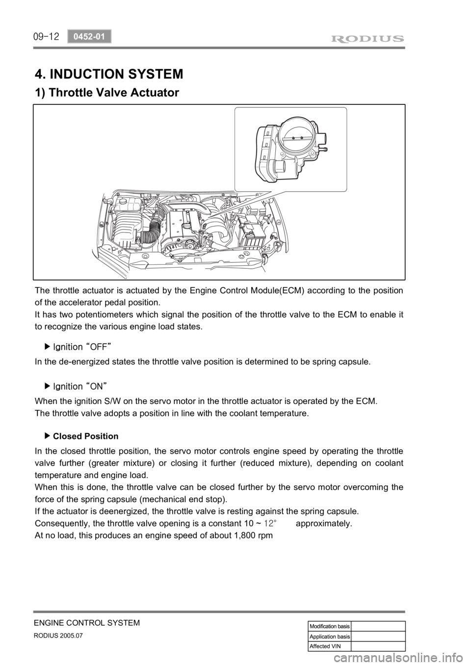
1) Throttle Valve Actuator
The throttle actuator is actuated by the Engine Control Module(ECM) according to the position
of the accelerator pedal position.
It has two potentiometers which signal the position of the throttle valve to the ECM to enable it
to recognize the various engine load states.
In the de-energized states the throttle valve position is determined to be spring capsule.
Ignition “ON” ▶
When the ignition S/W on the servo motor in the throttle actuator is operated by the ECM.
The throttle valve adopts a position in line with the coolant temperature.
In the closed throttle position, the servo motor controls engine speed by operating the throttle
valve further (greater mixture) or closing it further (reduced mixture), depending on coolant
temperature and engine load.
When this is done, the throttle valve can be closed further by the servo motor overcoming the
force of the spring capsule (mechanical end stop).
If the actuator is deenergized, the throttle valve is resting against the spring capsule.
Consequently, the throttle valve opening is a constant 10 ~ 12° approximately.
At no load, this produces an engine speed of about 1,800 rpmClosed Position ▶
Page 262 of 502
0-10
RODIUS 2005.07
4892-01
ABS SYSTEM
3. ON-VEHICLE SERVICE
(1) Electronic system service precautions
Take care to avoid electronic brake control module (HECU) circuit overloading. In testing for
opens or shorts, do not ground or apply voltage to any circuit unless instructed to do so by the
diagnostic procedure. Test circuits only with a high-impedance multi-meter. Never remove o
r
apply power to any control module with the ignition switch in the ON position. Always turn the
ignition to the OFF position before removing or connecting battery cables, fuses or connectors.
(2) General service precautions
Disconnect the HECU connector before performing any vehicle welding work using an electric
arc welder. Do not attempt to disassemble any component designated as nonserviceable. The
hydraulic modulator and the HECU can be seperated. (There is however no access to repai
r
the each components.)
(3) Bleeding system
Replacement modulators are shipped already filled and bled. In normal procedures requiring
removal of the modulator, such as to replace the HECU, air will not enter the modulator, and
normal bleeding will be all that is needed.
If air enters the hydraulic modulator, or if an unfilled modulator is installed, use the brake
bleeding program in the scan tool to bleed the modulator. Manual bleeding of the hydraulic
modulator is not possible.
1) Service Precautions
Brake Fluid may irritate eyes and skin. In case of contact, take the following actions:
Eye contact - rinse thoroughly with water.
Skin contact - wash with soap and water.
Ingestion - consult a physician immediately. -
-
-
To help avoid personal injury due to poor braking. DO NOT Tap into the vehicle’s
brake system to operate a trailer brake system.
When fasteners are removed, always reinstall them at the same location from which they
were removed. If a fastener needs to be replaced, use the correct part number fastener
for is not available, a fastener of equal size and strength (or stronger) may be used.
Fasteners that are not reused, and those requiring thread-locking compound will be
called out. The correct torque values must be used when installing fasteners that require
them. If the above procedures are not followed, parts or system damage could result.