tow SSANGYONG RODIUS 2005 Service Manual
[x] Cancel search | Manufacturer: SSANGYONG, Model Year: 2005, Model line: RODIUS, Model: SSANGYONG RODIUS 2005Pages: 502, PDF Size: 70.43 MB
Page 128 of 502
04-5
ENGINE INTAKE SYSTEM
RODIUS 2005.07
1715-01
2. RESONANCE FLAP
1) Function
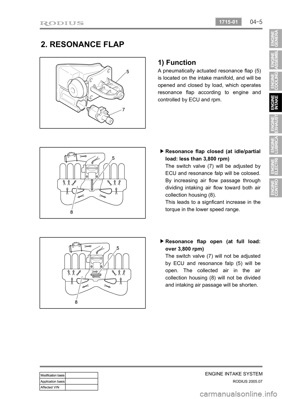
A pneumatically actuated resonance flap (5)
is located on the intake manifold, and will be
opened and closed by load, which operates
resonance flap according to engine and
controlled by ECU and rpm.
Resonance flap closed (at idle/partial
load: less than 3,800 rpm)
The switch valve (7) will be adjusted by
ECU and resonance falp will be colosed.
By increasing air flow passage through
dividing intaking air flow toward both ai
r
collection housing (8).
This leads to a signficant increase in the
torque in the lower speed range. ▶
Resonance flap open (at full load:
over 3,800 rpm)
The switch valve (7) will not be adjusted
by ECU and resonance falp (5) will be
open. The collected air in the ai
r
collection housing (8) will not be divided
and intaking air passage will be shorten. ▶
Page 239 of 502
0-6
RODIUS 2005.07
4892-01
ESP SYSTEM
3. ESP SYSTEM DESCRIPTION
1) Principle of ESP
ESP (Electronic Stability Program) recognizes critical driving conditions, such as panic
reactions in dangerous situations, and stabilizes the vehicle by wheel-individual braking and
engine control intervention with no need for actuating the brake. This system is developed to
help the driver avoid the danger of losing the control of the vehicle stability due to under-
steering or over-steering during cornering.
The yaw rate sensor, lateral sensor and longitudinal sensor in the sensor cluster and the
steering wheel angle sensor under the steering column detect the spin present at any wheels
during over-steering, under-steering or cornering. The ESP ECU controls against over-steering
or under-steering during cornering by controlling the vehicle stability using the input values from
the sensors and applying the brakes independently to the corresponding wheels.
The system also controls during cornering by detecting the moment right before the spin and
automatically limiting the engine output (coupled with the ASR system).
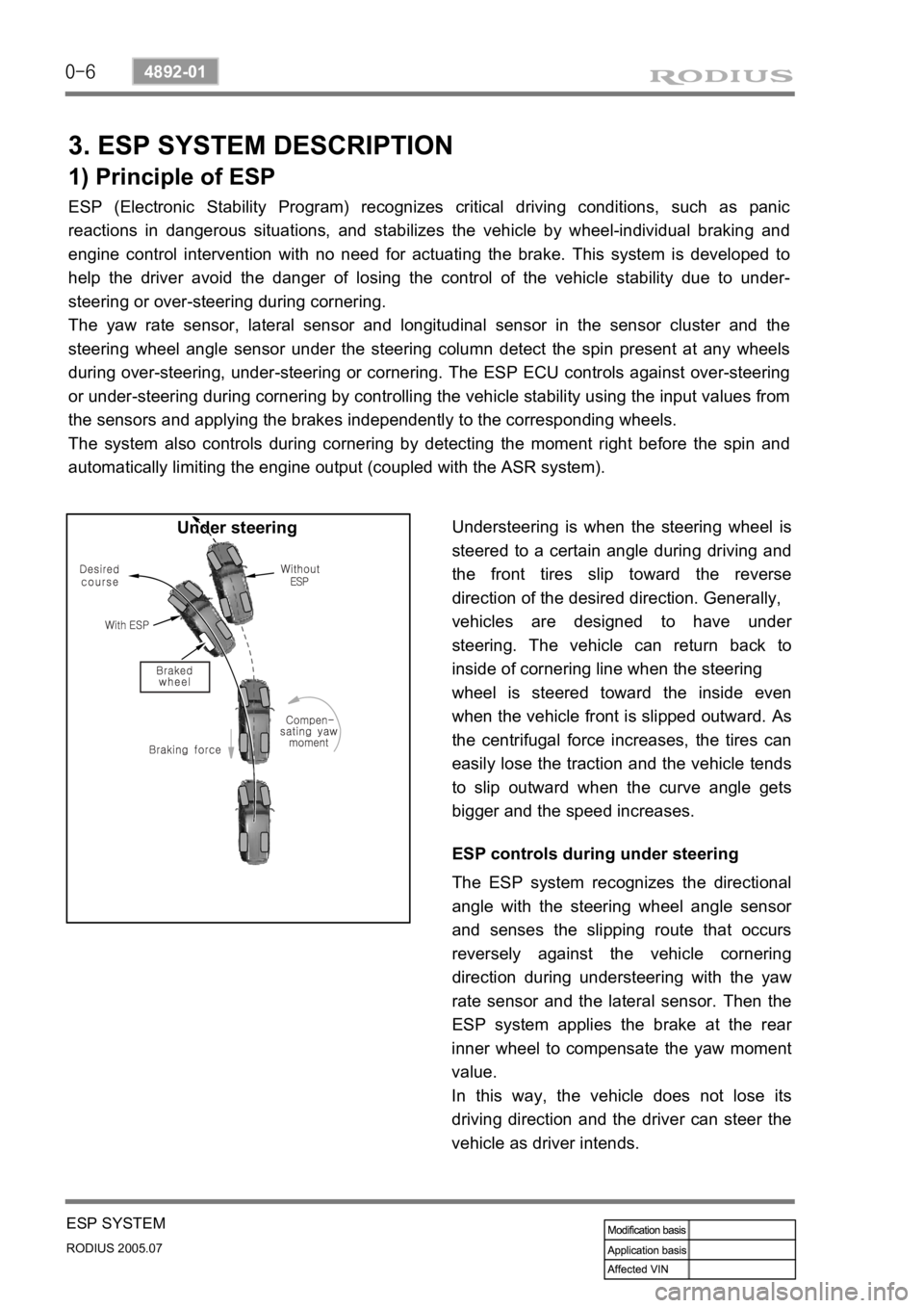
Understeering is when the steering wheel is
steered to a certain angle during driving and
the front tires slip toward the reverse
direction of the desired direction. Generally,
vehicles are designed to have unde
r
steering. The vehicle can return back to
inside of cornering line when the steering
wheel is steered toward the inside even
when the vehicle front is slipped outward.
As
the centrifugal force increases, the tires can
easily lose the traction and the vehicle tends
to slip outward when the curve angle gets
bigger and the speed increases. Under steering
ESP controls during under steering
The ESP system recognizes the directional
angle with the steering wheel angle senso
r
and senses the slipping route that occurs
reversely against the vehicle cornering
direction during understeering with the yaw
rate sensor and the lateral sensor. Then the
ESP system applies the brake at the rea
r
inner wheel to compensate the yaw moment
value.
In this way, the vehicle does not lose its
driving direction and the driver can steer the
vehicle as driver intends.
Page 240 of 502
0-7
ESP SYSTEM
RODIUS 2005.07
4892-01
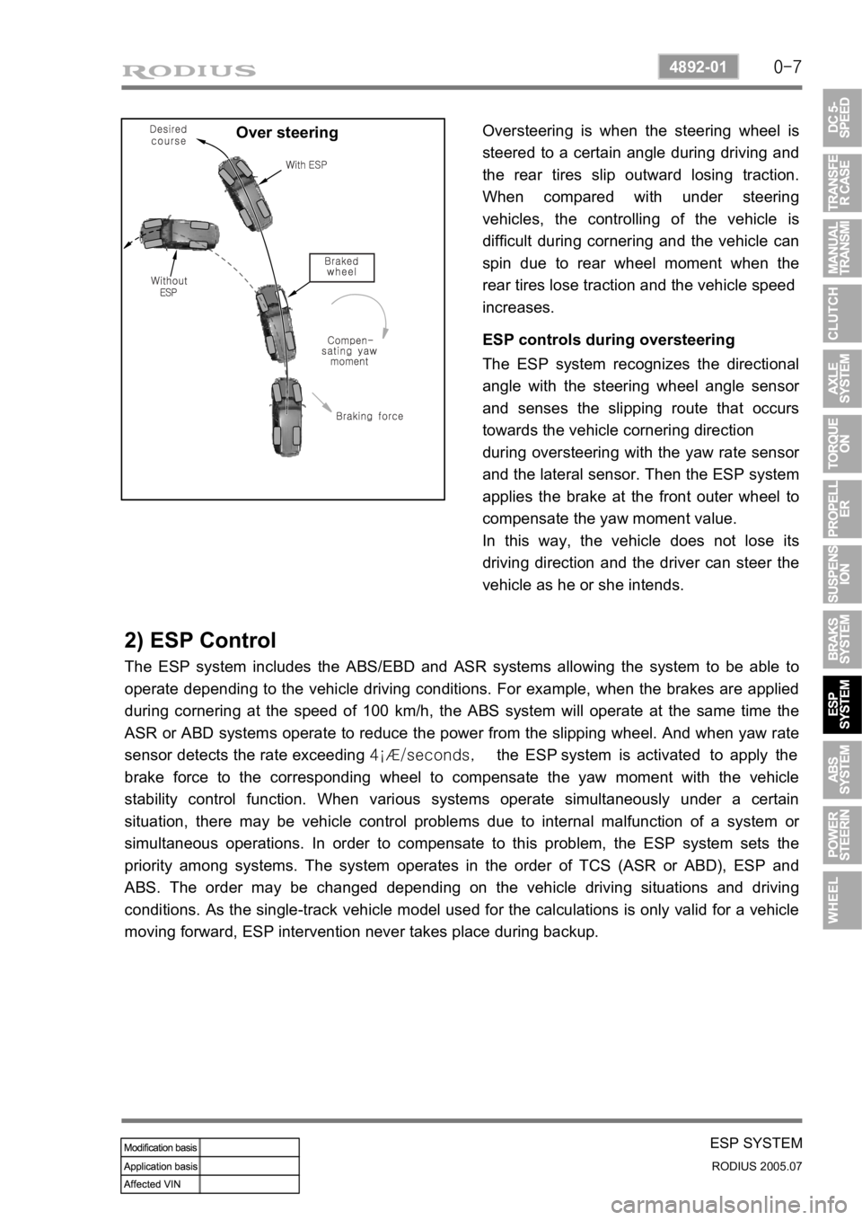
Over steeringOversteering is when the steering wheel is
steered to a certain angle during driving and
the rear tires slip outward losing traction.
When compared with under steering
vehicles, the controlling of the vehicle is
difficult during cornering and the vehicle can
spin due to rear wheel moment when the
rear tires lose traction and the vehicle speed
increases.
ESP controls during oversteering
The ESP system recognizes the directional
angle with the steering wheel angle senso
r
and senses the slipping route that occurs
towards the vehicle cornering direction
during oversteering with the yaw rate senso
r
and the lateral sensor. Then the ESP system
applies the brake at the front outer wheel to
compensate the yaw moment value.
In this way, the vehicle does not lose its
driving direction and the driver can steer the
vehicle as he or she intends.
2) ESP Control
The ESP system includes the ABS/EBD and ASR systems allowing the system to be able to
operate depending to the vehicle driving conditions. For example, when the brakes are applied
during cornering at the speed of 100 km/h, the ABS system will operate at the same time the
ASR or ABD systems operate to reduce the power from the slipping wheel. And when yaw rate
sensor detects the rate exceeding 4¡Æ/seconds, the ESP system is activated to apply the
brake force to the corresponding wheel to compensate the yaw moment with the vehicle
stability control function. When various systems operate simultaneously under a certain
situation, there may be vehicle control problems due to internal malfunction of a system o
r
simultaneous operations. In order to compensate to this problem, the ESP system sets the
priority among systems. The system operates in the order of TCS (ASR or ABD), ESP and
ABS. The order may be changed depending on the vehicle driving situations and driving
conditions. As the single-track vehicle model used for the calculations is only valid for a vehicle
moving forward, ESP intervention never takes place during backup.
Page 287 of 502
0-9
WHEEL
RODIUS 2005.07
4710-09
3) Caster
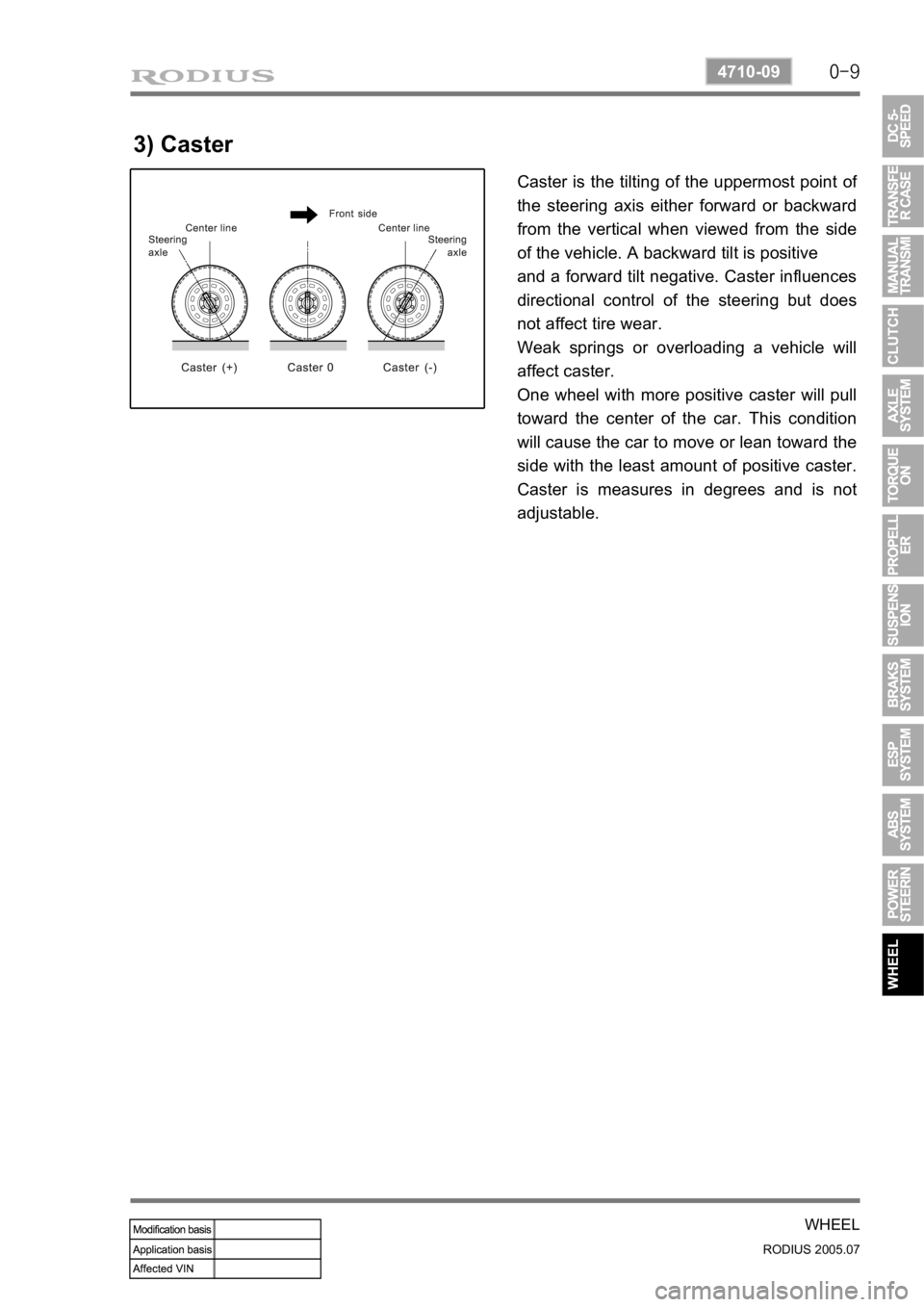
Caster is the tilting of the uppermost point of
the steering axis either forward or backward
from the vertical when viewed from the side
of the vehicle. A backward tilt is positive
and a forward tilt negative. Caster influences
directional control of the steering but does
not affect tire wear.
Weak springs or overloading a vehicle will
affect caster.
One wheel with more positive caster will pull
toward the center of the car. This condition
will cause the car to move or lean toward the
side with the least amount of positive caster.
Caster is measures in degrees and is not
adjustable.
Page 385 of 502
0-8
RODIUS 2005.07
8610-11
RAIN SENSOR
4) Washer Coupled Wiper Function
Check the washer coupled wiper operation by pressing the washer switch.
5) Irregular Operations (Abrupt Operations)
6) Self Diagnosis
Position the wiper switch to “AUTO” position and rotate the variable resistance knob from
“FAST” toward “SLOW” by one step.
At this moment, check if the wiper operates one cycle.
The wiper operates when the windshield glass is excessively worn or scratched, the windshield
glass is not cleared wiped due to using worn wiper blade or different wiper blade, or the rain
sensor is not improperly installed.Check the sensor for coming off.
Check the rain sensor cover installation.
Check that the customer is familiar to how to control the wiper sensitivity. -
-
-
If the wiper blade cannot wipe the glass uniformly and clearly, the irregular operations could be
occurred. And, the wiper blade should be replaced with new one with same specifications. Check that the customer can select the sensitivity by selecting the variable resistance value
(stage 1 to stage 5), that is, the wiper sensitivity control value. And, also check whether the
sensitivity is selected to the highest value of FAST (stage 5).
Check the wiper blade for wear. -
▶Poor sensing
▶Poor sensor
Rotate the variable resistance knob toward “SLOW” by 2 more steps. At this moment,
check if the wiper operates one cycle.
The wiper operates when the sensor is defective.