turn signal SSANGYONG RODIUS 2005 Service Manual
[x] Cancel search | Manufacturer: SSANGYONG, Model Year: 2005, Model line: RODIUS, Model: SSANGYONG RODIUS 2005Pages: 502, PDF Size: 70.43 MB
Page 47 of 502

CIRCUIT
1461-01/2820-01/1491-01/1491-01/8210-01/3670-01/3670-03/3410-01/4891-01/4920-01/4480-01/8810-01/8010-01/8610-04/8610-11/7421-60/8510-52/8610-17/8510
-
20
/
8710-03/8510-03/8710-03/8510-12/8610-09/7630-02/7340-03/8310-01/8510-00/8320-01/8510-26/8510-24/4810-10/8610-01/7770-07/8910-01/8730-01/6810-21/6910
-
01
/
6810-30/6810-30
CIRCUIT
ENGINE
8910-01 AUDIO (MULTI VISION)................
8910-01 AUDIO..........................................
8730-01 PARKING AID CIRCUIT................
6810-21 PTC HEATER (POSITIVE
TEMPERATURE
COEFFICIENT).............................
6910-01 FFH (FUEL FIRED HEATER).........
6810-30 FATC (FULL AUTO TEMP.
CONTROL) CIRCUIT....................
6810-30 AIR-CON (MANUAL).....................
CHASSIS3670-01 TCU (5-SPEED)............................
3670-03 TOD.............................................
3410-01 TCCU...........................................
4891-01 ABS/ESP......................................
4920-01 EPB..............................................
4480-01 EAS..............................................ELECTRIC
8610-17 DEFFOGER (FRT GLASS, RR
GLASS, OUTSIDE MIRROR)........
8510-20 FRT SEAT WARMER...................
8510-20 AUTO LIGHT CORTROL CIRC.....
8710-03 STICS..........................................
8510-03 POWER WINDOW CIRCUIT.........
8710-03 CENTRAL DOOR LOCKING
CIRCUIT.......................................
8510-12 RR WIPER & WASHER
CIRCUIT.......................................
8610-09 HORN...........................................
7630-02 CIGAR LIGHTER, POWER
OUTLET......................................
7340-03 SUN ROOF CIRCUIT....................
8310-01 HEAD LAMP & DRL (DAY TIME
RUNNING LIGHT) UNIT
CIRCUIT.......................................
8510-00 HEAD LAMP LEVELING DEVICE
CIRCUIT.......................................
8320-01 TAIL LAMP CIRCUIT...................
8510-26 TURN SIGNAL & HAZARD LAMP
CIRCUIT.......................................
8510-24 FOG LAMP CIRCUIT....................
4810-10 STOP & BACK-UP LAMP
CIRCUIT.......................................
8610-01 INTERIOR LAMP(ROOM,
G/HENDLE, DOOR COURTESY)
CIRCUIT......................................
7770-07 AUTO DIMMING ROOM MIRROR
CIRCUIT....................................... 8810-01 AIR-BAG.......................................
8010-01 CLUSTER.....................................
8610-04 MULTI METER.............................
8610-11 RAIN SENSING WIPER
CIRCUIT.......................................
7421-60 DRIVER POWER SEAT
CIRCUIT.......................................
8510-52 ELECTRIC OUTSIDE MIRROR &
FOLDING CIRCUIT.......................49
52
53
54
55
56
59
12
14
15
16
18
19
20
21
24
25
26
2728
29
30
31
35
36
37
38
39
40
41
42
43
44
45
46
47
48 1461-01 STARTING & CHARGING............
2820-01 PREHEATING UNIT CIRCUIT
(XDi))............................................
1491-01 ECU (ENGINE CONTROL UNIT -
XDi)..............................................
1491-01 ECU (GSL G32)............................
8210-01 DIAGNOSIS CIRCUIT...................3
4
5
8
11
Page 69 of 502

0-23
CIRCUIT
RODIUS 2005.07
8010-01
3)
(1) CONNECTOR INFORMATION
(2) CONNECTOR IDENTIFICATION SYMBOL & PIN NUMBER POSITION
WARNING (BAT CHANGE, OIL, BRAKE ENG CHCK, AIR BAG,
IMMOM SEAT-BELT) TURN SIGNAL, DEFOGGER, DOOR OPEN
Page 90 of 502

0-44RODIUS 2005.07
8510-26
CIRCUIT8510-26
TURN SIGNAL & HAZARD LAMP CIRCUIT
2) CONNECTOR IDENTIFICATION SYMBOL & PIN NUMBER POSITION
1) CONNECTOR INFORMATION
Page 125 of 502

07-9
ENGINE COOLING SYSTEM
RODIUS 2005.07
2110-01
8) A/C ON
The ECM will turn the cooling fans on at low speed when the A/C system is on. The ECM
will change to high speed when the high side A/C pressure reaches 1860 kPa (269.8 psi).
The cooling fans will return to low speed when the high side A/C pressure reaches 1378 kPa
(199.8 psi). ·
·
9) ENGINE COOLANT TEMPERATURE SENSOR
The Engine Coolant Temperature (ECT) sensor uses a temperature to control the signal
voltage to the Engine Control Module (ECM).
10) COOLANT TEMPERATURE GAUGE
The coolant temperature gauge controls the instrument panel temperature indicator. The
coolant temperature gauge is located with ECT sensor.
Page 156 of 502

09-10
RODIUS 2005.07
0452-01
ENGINE CONTROL SYSTEM
1) Starting Mode
When the ignition is turned ON, the ECM turns the fuel pump relay on for 1 second.
The fuel pump then builds fuel pressure.
The ECM also checks the Engine Coolant Temperature (ECT) sensor and the Throttle Position
(TP) sensor and determines the proper air/fuel ratio for starting the engine.
This ranges from1.5 to 1 at -36°C (-33°F) coolant temperature to 14.7 to 1 at 94°C
(201°F) coolant temperature.
The ECM controls the amount of fuel delivered in the starting mode by changing how long the
fuel injector is turned on and off.
This is done by ‘‘pulsing” the fuel injectors for very short times.
<007b008f008c00470099009c0095004700940096008b008c0047008f0088009a0047009b009e00960047008a00960095008b0090009b009000960095009a0047008a008800930093008c008b004702c402c400960097008c00950047009300960096009702
c9004700880095008b004702c402c4008a00930096009a008c>d loop”.
2) Run Mode
3) Open Loop
When the engine is first started and it is above 690 rpm, the system goes into “open
loop” operation. In “open loop”, the ECM ignores the signal from the O2S and calculates
the air/fuel ratio based on inputs from the ECT sensor and the MAF sensor.
The ECM stays in “open loop” until the following conditions are met:
The O2 has a varying voltage output, showing that it is hot enough to operate properly.
<007b008f008c0047006c006a007b0047009a008c0095009a0096009900470090009a0047008800890096009d008c004700880047009a0097008c008a0090008d0090008c008b0047009b008c00940097008c00990088009b009c0099008c0047004f005900
5900550047005c00b6006a00500055>
A specific amount of time has elapsed after starting the engine. -
-
-
4) Closed Loop
The specific values for the above conditions vary with different engines and are stored in the
Electronically Erasable programmable Read-Only Memory (EEPROM).
When these conditions are met, the system goes into “closed loop” operation. In “closed
loop”, the ECM calculates the air/fuel ratio (fuel injector on-time) based on the signals
from the O2 sensors.
This allows the air/fuel ratio to stay very close to 14.7 to 1.
5) Acceleration Mode
The ECM responds to rapid changes in throttle position and airflow and provides extra fuel.
The ECM responds to changes in throttle position and airflow and reduces the amount of fuel.
When deceleration is very fast, the ECM can cut off fuel completely for short periods of time.
6) Deceleration Mode
Page 212 of 502

0-5
TORQUE ON DEMAND
RODIUS 2005.07
3240-01
2. GENERAL DESCRIPTION
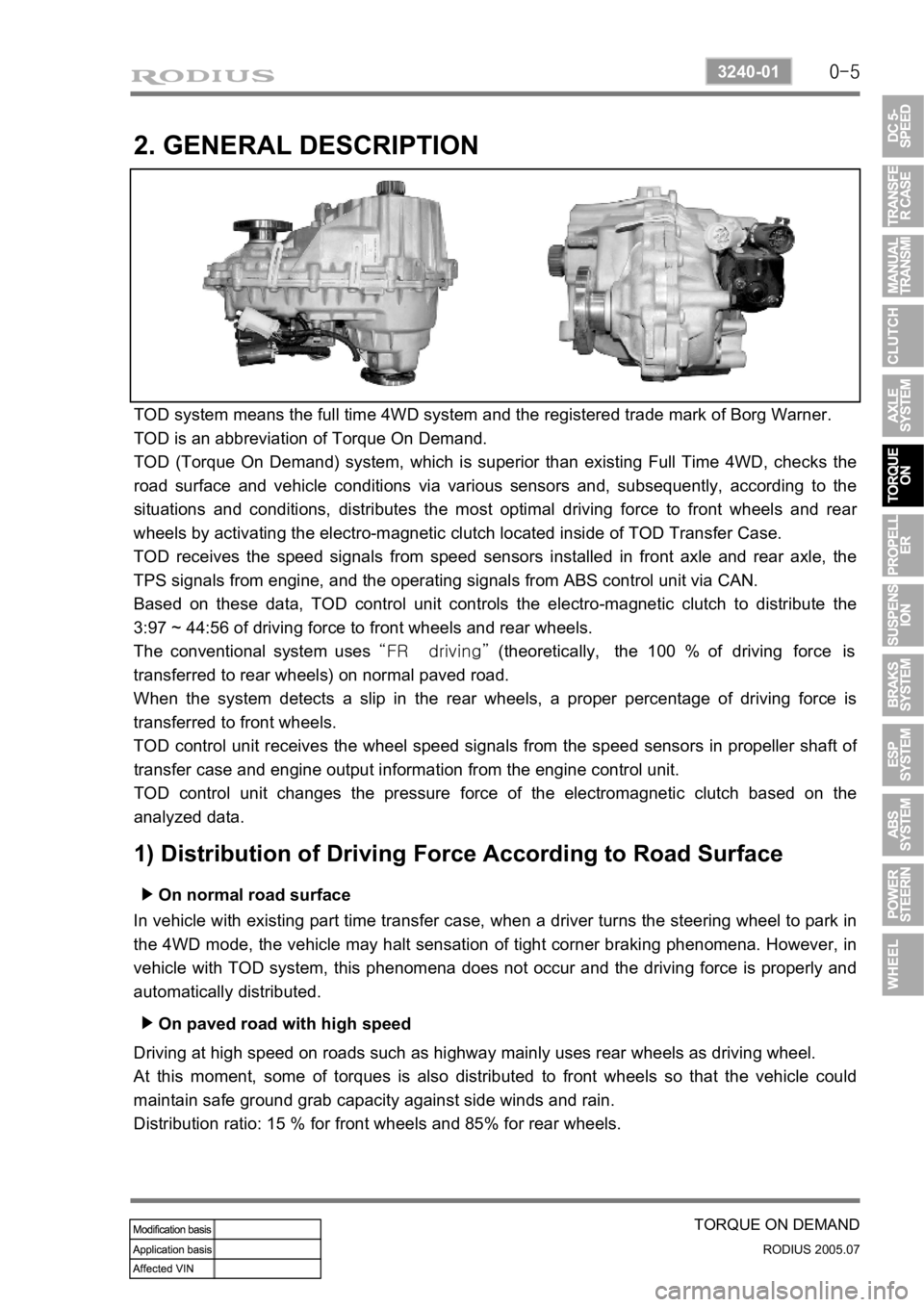
TOD system means the full time 4WD system and the registered trade mark of Borg Warner.
TOD is an abbreviation of Torque On Demand.
TOD (Torque On Demand) system, which is superior than existing Full Time 4WD, checks the
road surface and vehicle conditions via various sensors and, subsequently, according to the
situations and conditions, distributes the most optimal driving force to front wheels and rea
r
wheels by activating the electro-magnetic clutch located inside of TOD Transfer Case.
TOD receives the speed signals from speed sensors installed in front axle and rear axle, the
TPS signals from engine, and the operating signals from ABS control unit via CAN.
Based on these data, TOD control unit controls the electro-magnetic clutch to distribute the
3:97 ~ 44:56 of driving force to front wheels and rear wheels.
The conventional system uses “FR driving” (theoretically, the 100 % of driving force is
transferred to rear wheels) on normal paved road.
When the system detects a slip in the rear wheels, a proper percentage of driving force is
transferred to front wheels.
TOD control unit receives the wheel speed signals from the speed sensors in propeller shaft o
f
transfer case and engine output information from the engine control unit.
TOD control unit changes the pressure force of the electromagnetic clutch based on the
analyzed data.
1) Distribution of Driving Force According to Road Surface
On normal road surface ▶
In vehicle with existing part time transfer case, when a driver turns the steering wheel to park in
the 4WD mode, the vehicle may halt sensation of tight corner braking phenomena. However, in
vehicle with TOD system, this phenomena does not occur and the driving force is properly and
automatically distributed.
On paved road with high speed ▶
Driving at high speed on roads such as highway mainly uses rear wheels as driving wheel.
At this moment, some of torques is also distributed to front wheels so that the vehicle could
maintain safe ground grab capacity against side winds and rain.
Distribution ratio: 15 % for front wheels and 85% for rear wheels.
Page 321 of 502

0-8
RODIUS 2005.07
8710-01
STICS
If the washer operating signal is inputted while the wipers are operating in intermittent or
AUTO mode, the system stores the previous intermittent interval and operates the washe
r
coupled wiper. After then, the wiper operation returns back to intermittent or AUTO mode
with the stored operating interval. 3.
Page 322 of 502

0-9
STICS
RODIUS 2005.07
8710-01
(2) Rain Sensor Coupled Wiper
If equipped with RE-STICS rain sensor, has following operation system.
System layout ▶
This vehicle has a different wiper control logic compared to other models. As shown in the
system diagram, the rain sensor unit does not control wiper directly. The rain sensor unit sends
infrared rays signal through LED and then receives it with photo diode and then sends the
returned signal to STICS and the STICS controls the wipers directly.
For more details, refer to rain sensing wiper section in this manual.
Page 323 of 502

0-10
RODIUS 2005.07
8710-01
STICS
Rain sensing operation point ▶
The wiper relay is turned on and the wiper motor runs one cycle when the ignition key is
turned to “ON” position (while the wiper switch is in “AUTO” position).
The wiper relay (LO) is turned on and the wiper motor runs one cycle when changing the
wiper switch to “AUTO” position from any other positions (while the ignition key is in
“ON” position). When the wiper switch is turned to “AUTO” position again from other
positions, the system drives the wiper relay (LO) to run the wiper motor one cycle only when
the rain sensor detects the “Rain Detected” signal. 1)
2)
Rain sensing sensitivity control ▶
The wiper relay is turned on and the wiper motor runs one cycle when the volume sensitivity is
increased (ex: from 0 to 1) (while the ignition key is in “ON” position, the wiper switch is
in “AUTO” position, and the wiper motor is in “Parked” position). However, the wiper
motor can be operated only when the rain sensor detects the “Rain Detected” signal.
* If the volume sensitivity is changed more than 2 stages within 2 seconds, the wiper motor runs
only one cycle.
Page 325 of 502

0-12
RODIUS 2005.07
8710-01
STICS
Defective rain sensor ▶
The wiper relay (LO) is turned on and the wiper motor runs one cycle when the wipe
r
sensitivity is changed to 2 from 3 during receiving the malfunction signal (1) from the rain
sensor (while the ignition key is in “ON” position and the wiper switch is in “AUTO”
position). 1)
The wiper relay (LO) is turned on and the wiper motor runs one cycle when the wiper
sensitivity is changed to 3 from 4 during receiving the malfunction signal (2) from the rain
sensor (while the ignition key is in “ON” position and the wiper switch is in “AUTO”
position). 2)